ReproScan Flexx, Operator’s Manual vs 1.0
Contents
1.0 TECHNICAL SPECIFICATIONS ........................................................................................ 7
2.0 FLEXX FEATURES AND DESCRIPTIONS...................................................................... 7
2.1 FEATURES OF THE FLEXX ULTRASOUND UNIT .............................................................................................................................................7
2.1
FEATURES OF THE FLEXX ULTRASOUND UNIT ............................................................................................................................................8
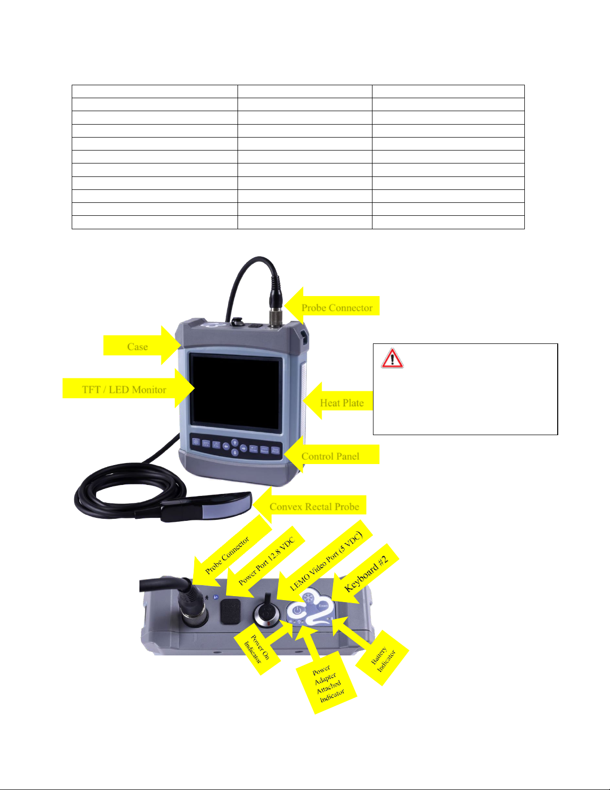
2.2
FLEXX COMPONENTS ...................................................................................................................................................................................8
2.3
FUNCTION KEYS............................................................................................................................................................................................9
3.0 FLEXX CONFIGURATIONS ............................................................................................. 10
3.1 TYPICAL CONFIGURATION FOR BEEF CATTLE ...........................................................................................................................................10
4.0 OPERATING CONDITIONS..............................................................................................11
4.1 POWER SUPPLY..........................................................................................................................................................................................11
4.2 OPERATION ENVIRONMENT .....................................................................................................................................................................11
4.3 STORAGE AND TRANSPORTATION ............................................................................................................................................................ 11
5.0 CONNECTING ULTRASOUND PROBES, VIEWING DEVICES AND POWER ...... 12
5.1 CONNECTING AN ULTRASOUND PROBE ...................................................................................................................................................12
5.2 DISCONNECTING AN ULTRASOUND PROBE .............................................................................................................................................. 12
5.3 VISTA GOGGLES INSTALLATION ................................................................................................................................................................ 13
5.4 NFI 5000 MONOCULAR INSTALLATION.................................................................................................................................................. 13
5.5 CONNECTING THE FLEXX TO A REPROSCAN 2.0 WIRELESS MONITOR................................................................................................... 13
5.6 CONNECTING THE POWER TO THE FLEX MODULE................................................................................................................................... 13
6.0 CHANGING SETTINGS AND OPERATING THE FLEXX ........................................ 14
6.1 STARTUP AND SHUTDOWN....................................................................................................................................................................... 14
6.2 SCREEN SAVER SETTING............................................................................................................................................................................. 14
6.3 CHANGING SETTINGS ON THE FLEXX ........................................................................................................................................................ 14
6.3.1
Language setting........................................................................................................................................14
6.3.2
TV Mode setting .........................................................................................................................................14
6.3.3
Status setting..............................................................................................................................................14
6.3.4
WiFi setting.................................................................................................................................................15
6.3.5
Grid On/Off setting.....................................................................................................................................15
6.3.6
Grid Spacing settings..................................................................................................................................15
6.3.7
Other settings interface..............................................................................................................................15
6.4 IMAGE ADJUSTMENT.................................................................................................................................................................................16
6.4.1
Total gain adjustment ................................................................................................................................16
6.4.2
Near field gain adjustment.........................................................................................................................16
6.4.3
Far field gain adjustment ...........................................................................................................................16
6.4.4
Dynamic range adjustment ........................................................................................................................16
6.4.5
Frequency adjustment................................................................................................................................17
6.4.6
Frame correlation adjustment....................................................................................................................17
6.4.7
Image post-process adjustment .................................................................................................................17
6.4.8
Edge enhancement adjustment..................................................................................................................17
6.4.9
Probe Orientation L/R adjustment..............................................................................................................17
6.4.10
Focus position adjustment........................................................................................................................17
6.4.11
Depth range selection...............................................................................................................................17
6.4.12
Flexx monitor image brightness and contrast adjustment.......................................................................18
6.5 IMAGE FREEZE/UNFREEZE........................................................................................................................................................................18
6.6 DIAGNOSTIC MODE PRESET.......................................................................................................................................................................18