PROSIXCT-EU
Wireless Door/Window Sensor
Installation and Setup Guide
The PROSIXCT-EU is a wireless door/window sensor with
cover and wall tamper. It is intended for use with Control
Panels that support SiX™ series devices. The sensor
consists of two primary components: the main sensor body
(transmitter) and the magnet housing.
In addition, the PROSIXCT-EU sensor has an internal
terminal block for connecting to an external, two-wired
sensor. When connected, the PROSIXCT-EU can then
monitor the status of that external sensor (tamper or alarm).
A maximum of 127 monitored devices (keypads, smoke
alarms, sensors, hand-held devices, etc.) can be connected
to the Control Panel.
Note: Installation shall be done in accordance with local
regulations.
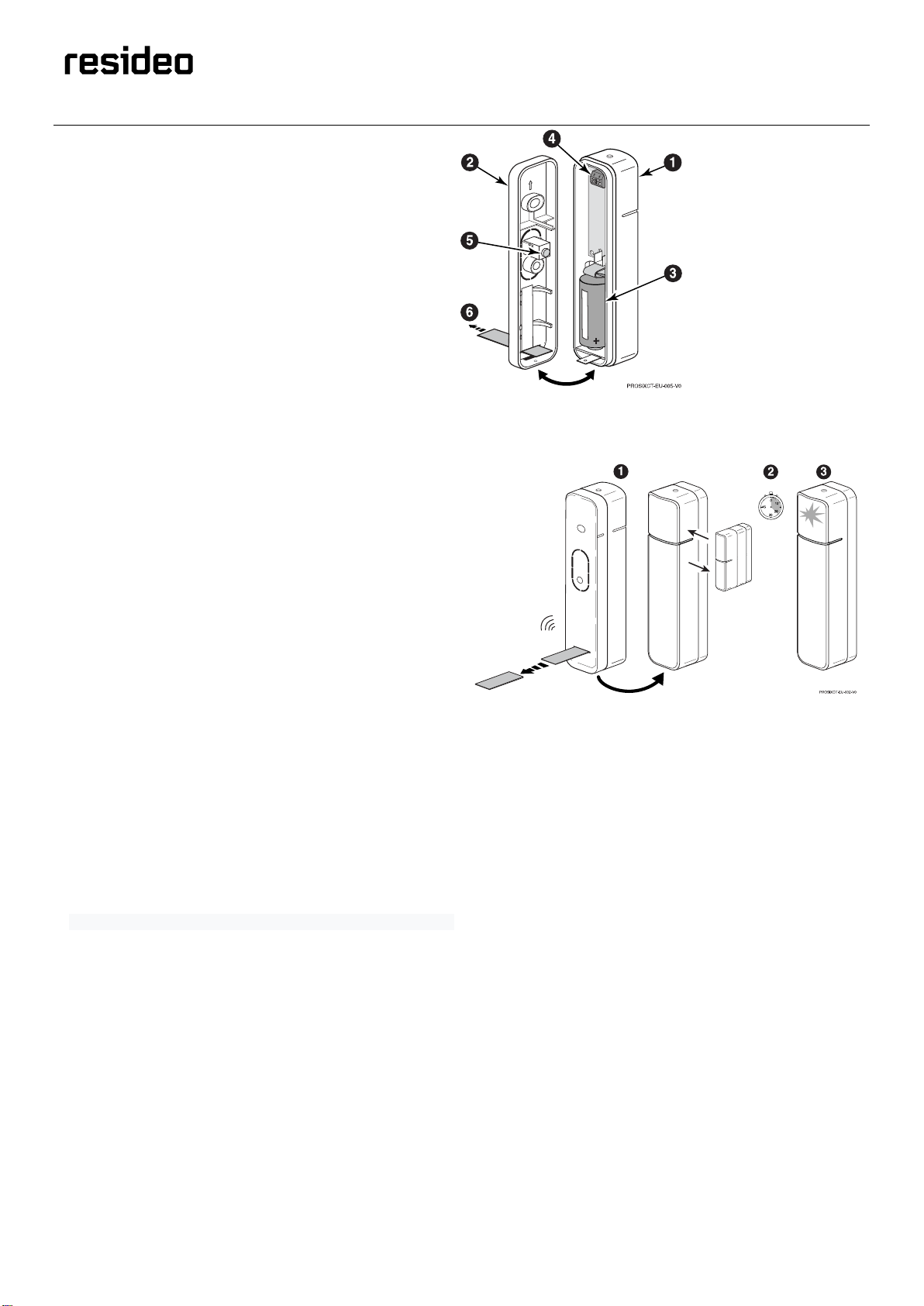
1. Front Cover
2. Rear Mounting Plate
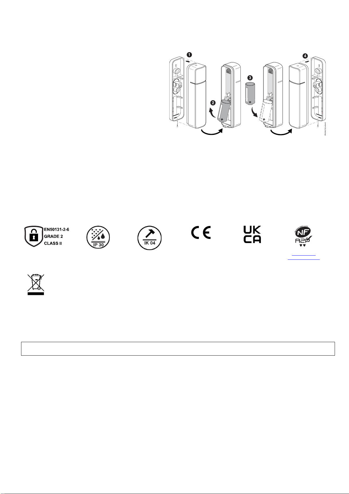
3. Battery
4. Terminal Block
5. Tamper Switch
6. Battery Tab
You must enroll the sensor in the Control Panel. Refer to the panel programming instruction for detailed procedures.
Note: Because the battery tab is removed from the back of the main body, enrollment must be performed prior to mounting.
Set the panel to the Programming Mode and when prompted:
1. From the back of the main body, pull out the battery tab to
activate the sensor (or use the magnet to activate the
internal sensor contact switch if the battery tab has
already been removed).
2. The LED flashes (up to about 20 seconds*) during
enrollment.
•Both services (sensor contact switch and Terminal
Block) are enrolled in sequential/next available zone
numbers.
•The sensor sends data, and the panel registers the
sensor.
*Note: Enrollment time may vary depending on the signal
strength between the sensor and the panel.
3. When completed, the LED is ON for 3 seconds to confirm
enrollment.
Note: If the sensor is not successfully enrolled during the
enrollment period, the LED turns off and the sensor
powers down. Activate a tamper, wired service (loop), or
the sensor contact switch to restart the enrollment
process.
4. Program each zone being used (sensor contact switch or
Terminal Block Zone).
Note:For detailed programming instructions refer to the
Installation Instructions for the Control Panel with which this
device is used.
IMPORTANT:
•After enrolling, verify an adequate signal strength by
conducting a sensor test (see panel instructions) with the
sensor in its intended mounting location. Adjust the sensor
location and orientation as necessary.
•After enrolled in a system, the senor cannot be used with
another Control Panel until it is removed from the current
panel. See the panel instructions for details.