resideo PROSIXPIR-EU Assembly instructions

PROSIXPIR-EU
Wireless Passive Infrared Motion Sensor
Installation and Setup Guide
The PROSIXPIR-EU wireless passive infrared motion sensor is intended for use with Control Panels that supports SiX™ series
devices. A maximum of 127 monitored devices (keypads, smoke alarms, sensors, hand-held devices, etc.) can be connected to
the Control Panel.
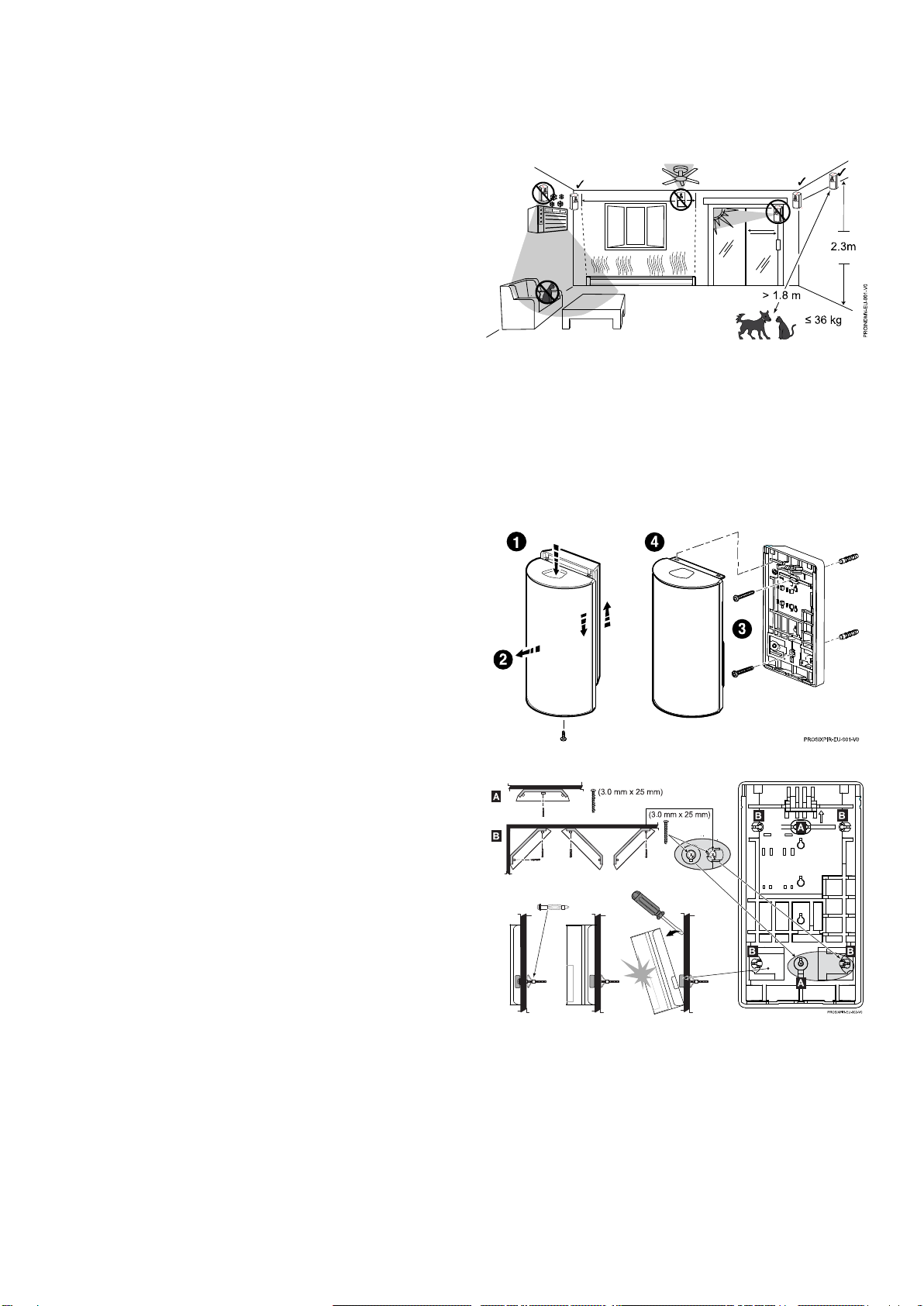
Note: Installation shall be done in accordance with local regulations.
ENROLLING
You must enroll the device in the Control Panel. Programming and
Testing is conducted through the AlarmNet 360™ cloud-based
management platform. The Sensor Learn mode is used to program
sensors.
With the panel in Programming Mode:
1. Remove screw and press down on the top latch to separate the
front cover from the rear case.
2. Remove the battery tab to activate and begin the enrollment
process.
3. The green LED beneath the battery flashes (up to about 20
seconds*) during enrollment.
The device sends data, and the panel registers the device.
* Enrollment time varies depending on the signal strength
between the device and the panel.
4. Enrollment is confirmed when the LED is ON for 3 seconds.
Note: If the sensor is not successfully enrolled during the
enrollment period, the LED turns off and the device enters a
sleep mode. Activate a tamper or remove and reinsert the
battery to restart the enrollment process.
Note: Pet Immunity is selectable: Off or Up to 36 kg.
Note: After enrolled in a system, the device cannot be used
with another Control Panel until it is removed from the current
panel. See the panel instructions for details.
Note:For detailed programming instructions refer to the
Installation Instructions for the Control Panel with which this
device is used.
24-HOUR ENROLLMENT DELETION AND DEFAULT
If the sensor is enrolled in a Control Panel different than the
intended panel, and you are unable to delete it from the
unintended panel, reset default the device to factory default
setting:
1. Remove screw and press down on the top latch to separate
the front cover from the rear case.
2. Remove the battery.
3. Press and hold the tamper switch.
4. Reinsert the battery and release the tamper switch when the
LED flashes rapidly for 2 seconds.
5. Install the front cover and secure with screw.
This procedure is available for 24 hours after enrollment with a
panel and the device remains powered (battery installed).

INSTALLATION GUIDELINES
Programming and RF testing should be done while the device is in its intended mounting location to ensure good communication
between the Control Panel and the device.
Mounting Considerations
•Mount indoors in a temperature-controlled environment.
•Mounting height should be 2.1 –2.7 m, with an optimal
range height of 2.3 m.
•Allow a clear line-of-sight to all areas to protect.
•Do not aim detector at windows, especially those in direct
sunlight, or at heat sources (fireplaces, radiators, and
heating vents, etc.).
•Avoid mounting in areas with high humidity (such as
garages) to minimize the risk of false alarms.
•Do not aim detector at moving objects such as fans.
•Do not paint or cover the detection or camera lens.
•For use in applications with pets up to 36 kg.
In Applications with Animals:
•Mount with the center of the device at 2.3 m.
•Mount where pet cannot come within 1.8 m of the sensor by climbing on furniture, stairs, boxes or other objects.
•Test each installation to determine exact level of animal immunity; levels vary based on environmental differences and
amount of heat radiated by an animal.
MOUNTING
1. Press the latch on the top of the device.
2. Separate the rear case/wall mount.
3. Secure the rear case/wall mount in the desired location
with two screws. (See the Mounting Options section.
Note: Rear case must be mounted on a stud, solid wall, or
with a robust wall anchor.
4. Slide the device onto the rear case/wall mount bracket and
secure with screw.
Mounting Options
After enrolling, verify adequate signal strength by conducting a
sensor test with the device installed in its intended mounting
location (see the controller's instructions). Adjust the device
mounting location and orientation as necessary to achieve
maximum signal strength
The sensor can be mounted on the wall or in corners:
•[A] = Wall mounting holes.
•[B] = Corner mounting holes.
Note: The rear tamper plate MUST be mounted to a stud, solid
wood, or with a robust wall anchor.

DETECTION PATTERNS
Top View
Side View
Zones
A
18 Lower
B
46 Intermediate
C
36 Long
WALK TEST
After power up/enrollment, the sensor automatically enters a
10-minute Walk Test mode.
Note: the system must be disarmed to enter Test Mode and
can only be armed again after exiting the Walk Test mode.
1. Walk through the detection area [A] and observe the LED
[B]comes ON.
2. After 10 minutes, the sensor automatically exits the Test
mode, disables the LED, and enters a normal operation
mode.
To restart a 10-minute Test period, activate the Test mode with
the Control Panel (see the Control Panel instructions).
BATTERY REPLACEMENT
1. Remove screw and press down on the top latch to separate
the front cover from the rear case.
2. Remove the battery and wait 10 seconds, then insert a new
battery.
Note: See the Specifications section for recommended
replacement batteries.
3. Place the front cover and back case together. Slide the
front cover upward and secure with screw.
Battery Caution: Risk of fire, explosion, and burns. Do not
recharge, disassemble, heat above 55°C, or incinerate.
Dispose of used batteries properly. Keep away from children.
Note: Constant exposure to high or low temperature or high
humidity may reduce battery life.
SPECIFICATIONS
Range: 12 m x 17 m
Wall Mounting Height: 2.1 m –2.7 m (Optimal 2.3 m)
Battery: 1 x 3V, Lithium
•EVE CR123A
•Panasonic CR123A
•Duracell DL123A
RF Frequency: 2.4GHz (<20 dBm)
Tamper: Cover and Wall (reported separately to
panel)
Operating Temperature: -10°~ +55°C
Relative Humidity: 95% max., non-condensing
Dimensions (mm): 106 (H) x 60 (W) x 41 (D)
Weight: 115 g
Material: ABS Plastic
2621420044
www.cnpp.com
www.marque-nf.com
The product should not be disposed of with other household waste. Check for the nearest authorized collection centers or
authorized recyclers. The correct disposal of end-of-life equipment will help prevent potential negative consequences for
the environment and human health.
Product must be tested at least once each year
Any attempt to reverse-engineer this device by decoding proprietary protocols, de-compiling firmware, or any similar actions is strictly prohibited.
REFER TO THE INSTALLATION INSTRUCTIONS FOR THE CONTROL PANEL WITHWHICHTHIS DEVICE IS USED, FORDETAILS REGARDING
LIMITATIONS OF THE ENTIRE ALARM SYSTEM.

SUPPORT & WARRANTY INFORMATION
For the latest documentation, warranty, and support, please go to: www.resideo.com
Sécurité Communications SAS (SECOM)
1198, Avenue du Docteur Maurice Donat
06250 Mougins - FRANCE
Ademco 1 Ltd., 200 Berkshire Place
Winnersh Triangle, Berkshire,
RG41 5RD –UNITED KINGDOM
PROSIXPIR-EU
R800-26473B 10/21 Rev B
©2022 Resideo Technologies, Inc.
www.resideo.com
Other resideo Accessories manuals
Popular Accessories manuals by other brands

imtech
imtech iMatJet 12V 5Ah Instructions for use

White Rodgers
White Rodgers F145-0825 installation instructions

Vivid
Vivid CLV-401A user manual

Allen-Bradley
Allen-Bradley 871TM-M**NP18 Series user manual

JVC
JVC Multi-Format SDI Unit IF-C151HDG instructions

Stahl
Stahl SolConex 8579/31 Series operating instructions