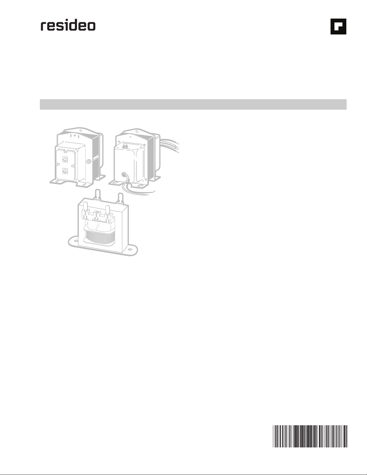
AT120A-E; AT140A-E; AT150A,B,D-F; AT160B; AT175A-D,F TRANSFORMERS
68-0054—06 2
SPECIFICATIONS
IMPORTANT
The specifications given in this publication do not
include normal manufacturing tolerances. Therefore,
a sample unit may not match the listed specifica-
tions exactly. Also, this product is built and tested
under closely controlled conditions, and some minor
differences in performance can be expected if those
conditions are changed.
Models: AT120A-E; AT140A-E; AT150A,B,D-F; AT160B;
AT175A-D,F.
Electrical Ratings: See Table 1.
aRefer to regulation curves.
bVoltage is 27.0V on AT150F and AT175F models.
Wiring Connections:
“A”, “C”, and “D” models: Primary—9 inch (230 mm) leadwires;
Secondary—screw terminals.
“B” and “E” models: Primary—9 inch (230 mm) leadwires or
fixed 1/4 inch (6 mm) quick-connects. Different length
leadwires and leadwires with stripped ends or with termi-
nals attached also available. Specify when ordering.
Secondary—9 inch (230 mm) leadwires or fixed 1/4 inch (6
mm) quick-connects. Different length leadwires, leadwires
with stripped ends or with terminals attached, and screw
terminals also available. Specify when ordering.
“F” models: Primary and Secondary—9 inch (230 mm) lead-
wires.
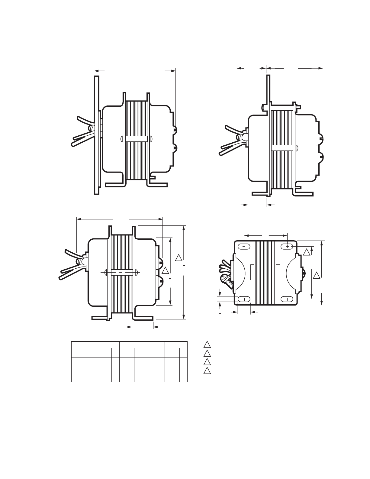
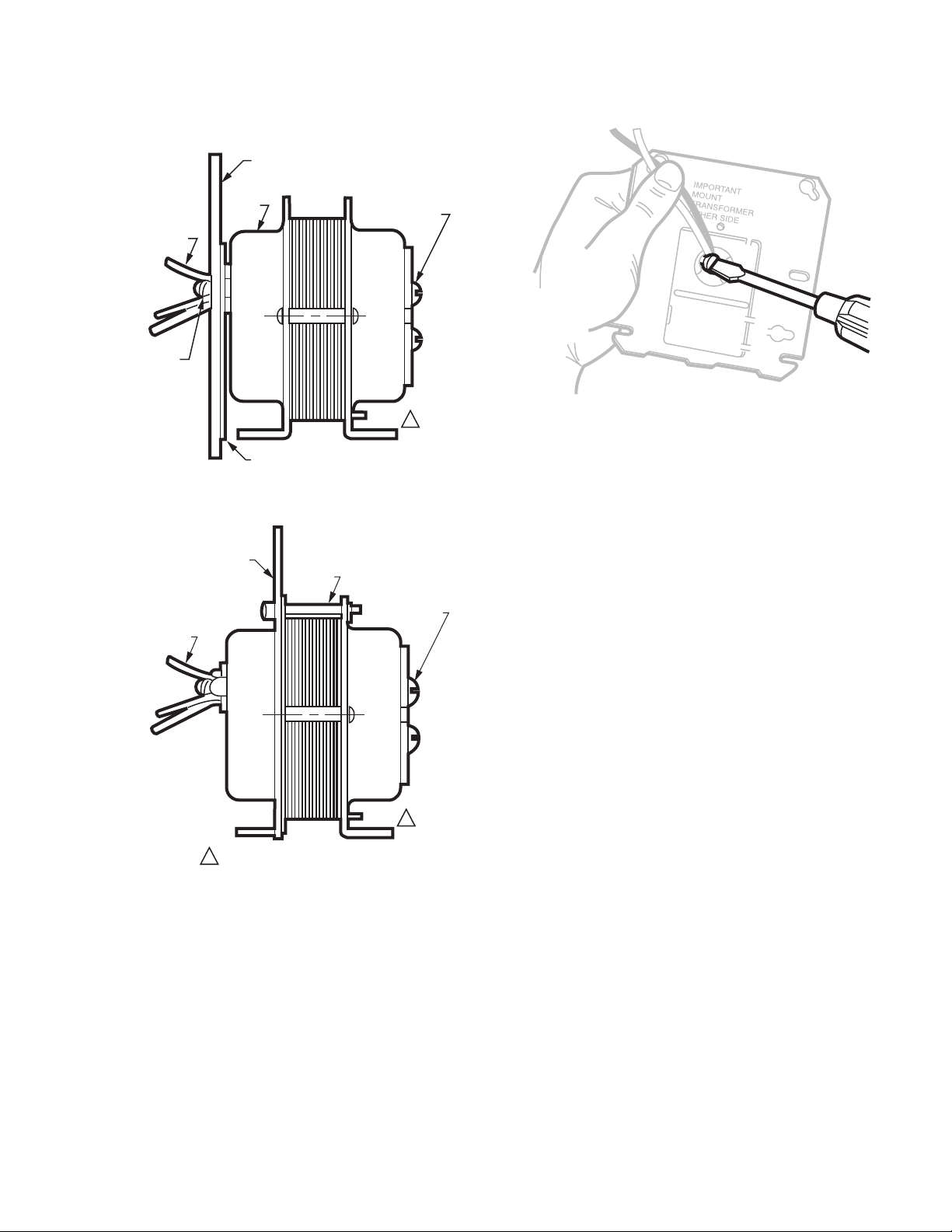
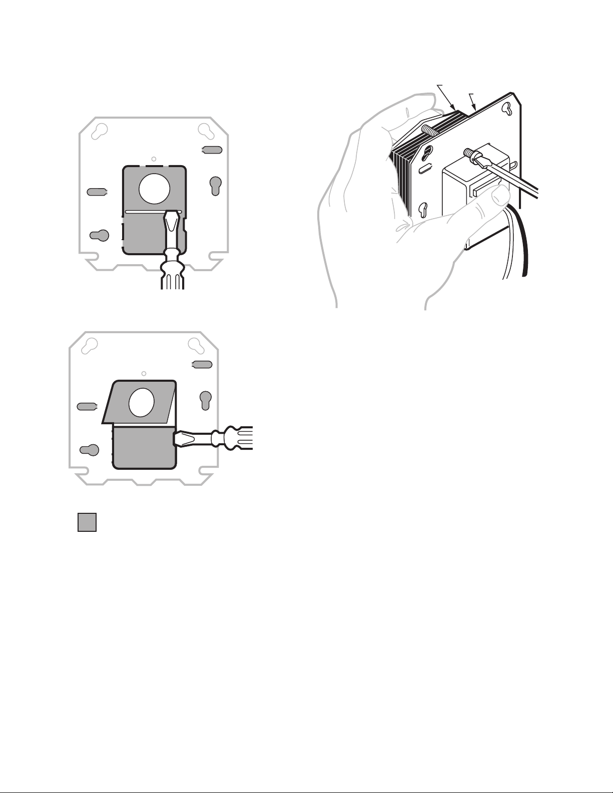
Mounting Means:
Dimensions: See Fig. 1 through 5.
Regulation:
See transformer regulation curves, Fig. 6 through 10.
Overcurrent Protection:
Inherent on AT120, AT140, and AT150. Thermal fusible link on
AT160 and AT175. Circuit breaker on AT150F and AT175F
models.
Approvals:
UNDERWRITERS LABORATORIES INC. LISTED (“A”, “C” and “F”
models): File No. E14881, Guide No. XOKV.
UNDERWRITERS LABORATORIES INC. COMPONENT RECOG-
NIZED (“B,” “D,” “E” models): File No. E14881, Guide No.
XOKV2.
All models conform to Underwriters Laboratories Inc. Stan-
dard UL 1585.
NATIONAL ELECTRICAL CODE: Class 2 not wet, Class 3 wet.
Optional Specifications:
End bells or caps on “B” through “E” models.
Terminations on “B” through “E” models.
Circuit breaker reset button on “F” models.
National Electrical Code:
Class 2 not wet, Class 3 wet
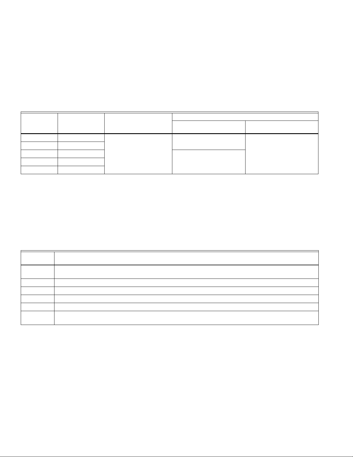
Table 1. Electrical Ratings.
Model
Number
Output Rating at
100 Percent Power
FactoraPrimary Input Voltage
(60 Hz)
Secondary Output Voltage
Open Circuit At Rated Power Output
AT120 20 VA 120, 240, 277, 480, 120/240,
208/240, 240/277, 277/480,
120/208/240, 208/240/480,
or 208/277/480V
27.0 24.0
AT140 40 VA
AT150 50 VA 27.5b
AT160 60 VA
AT175 75 VA
Model Suffix
Letter Mounting Means
A Includes clamp for outlet box knockout, 4 x 4 inch mounting plate for 2 x 4 inch or 4 x 4 inch outlet box, and
mounting feet for surface mount.
B Foot-mounted.
C Includes clamp for outlet box knockout.
D Integral 4 x 4 inch mounting plate fits 2 x 4 inch or 4 x 4 inch outlet box.
E Panel mounted with two No. 8 screws (not included).
F Includes 1/2-14 NPSM conduit connector and lock nut for mounting on plate or panel (not included) with 7/8 in.
knockout, and mounting feet for surface mount.