© RESOL 09099_flowcon_s.monen.indd
F lo w C o n S
5 |
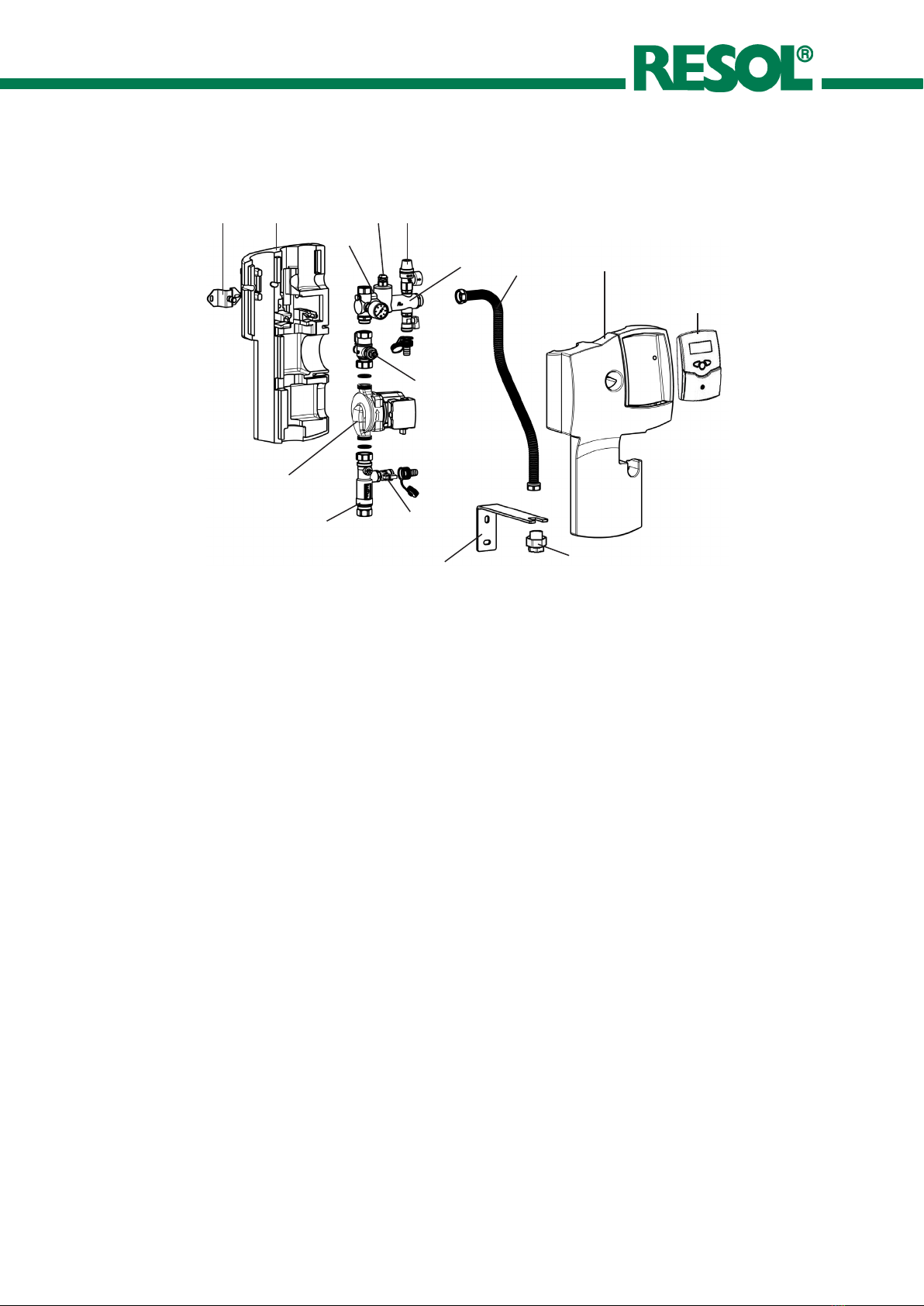
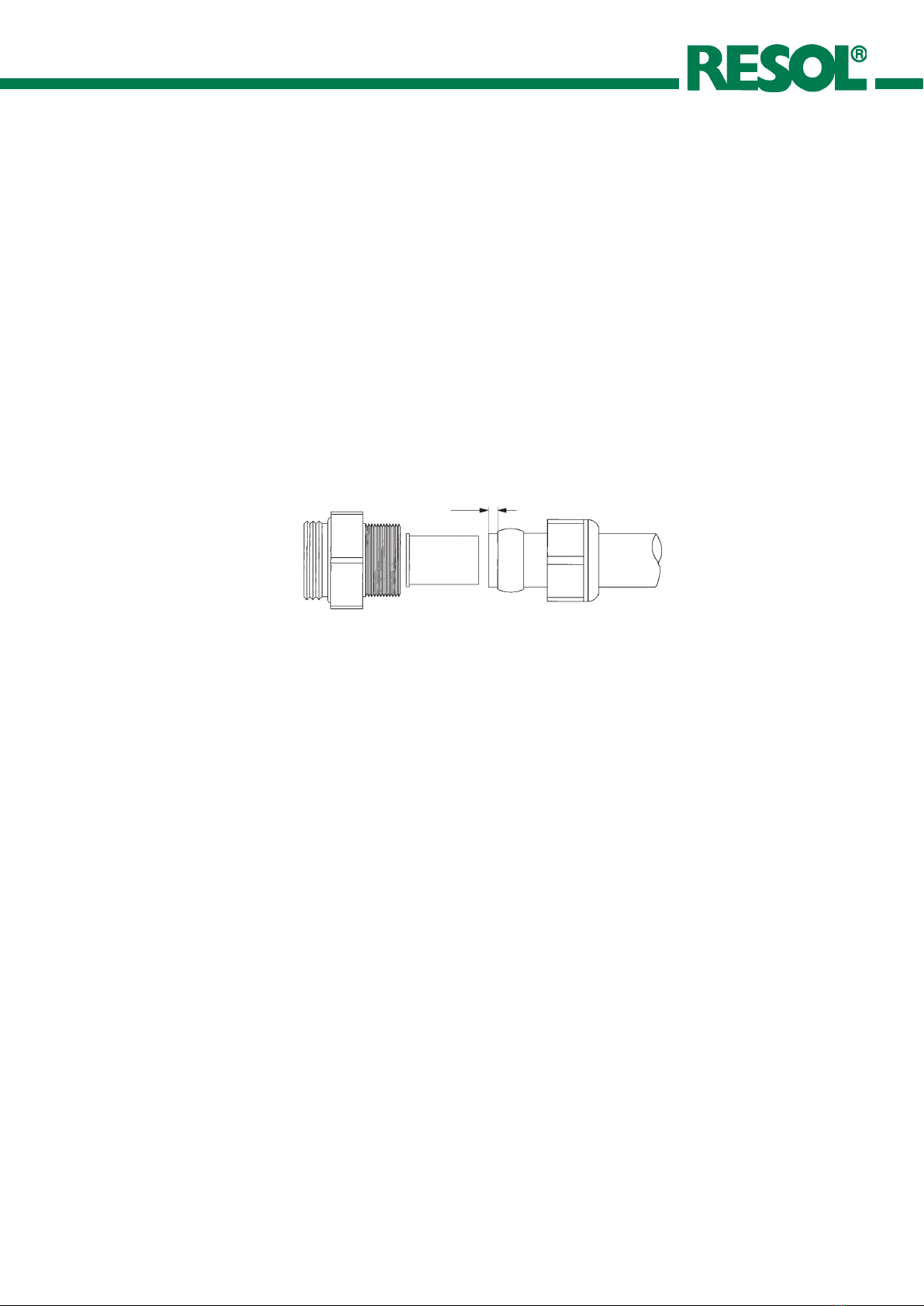
1.2 Mounting the pipes into a compression ring
connection
• First push the union nut (2) then the brass compression
ring (3) onto the copper pipe (1). To guarantee secure
load transmission and sealing, the pipe must extend at
least 3 mm out of the compression ring.
• Insert the support sleeve (4) into the copper pipe (1).
• Push the copper pipe (1) with the attached parts (2, 3
and 4) as far as possible into the body of the compres-
sion ring connection (5).
• First screw on the union nut by hand. Then tighten it
by at least one full rotation with a suitable open-ended
spanner.
2. Flushing and filling the system
• Connect the pressure hose to the fill and drain valve
below the manometer and open the valve.
• Connect the flushing hose to the fill and drain valve at
the flowmeter and open the valve.
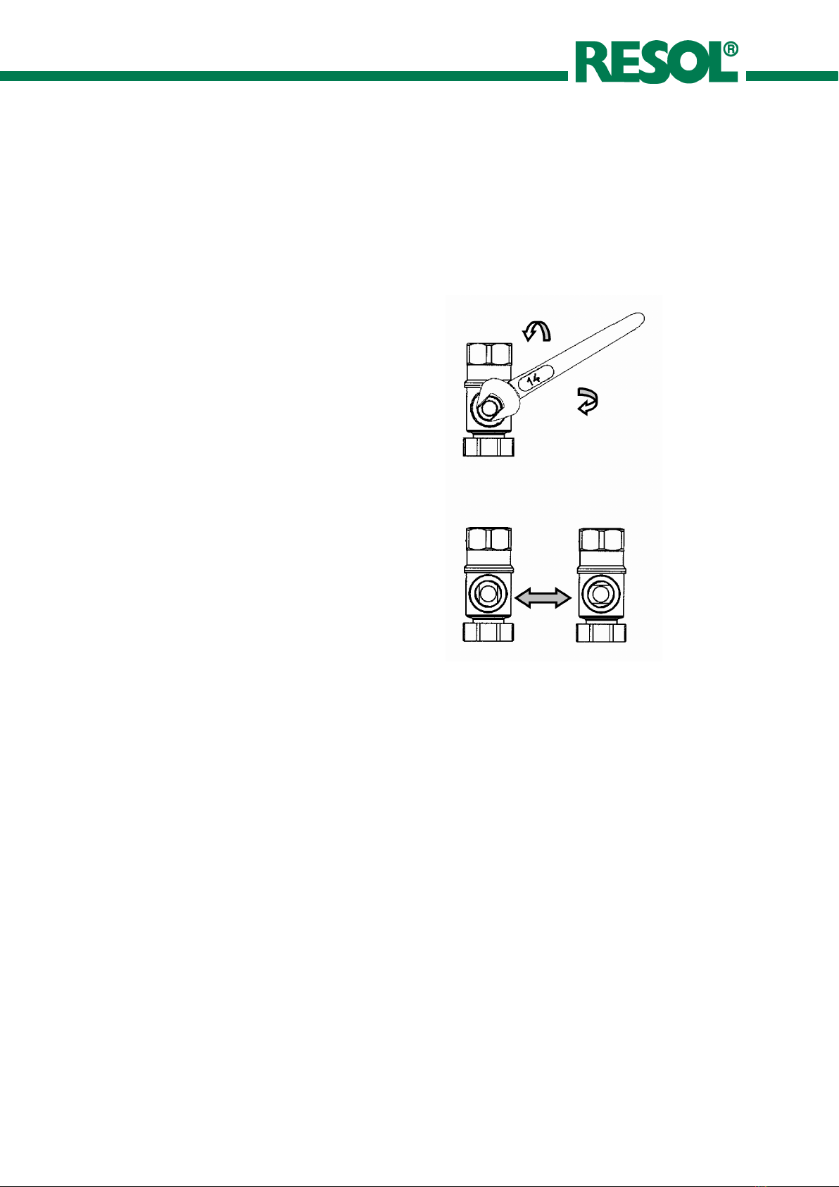
• The slot of the adjustment screw at the flowmeter has
to be in a horizontal position. Thus the integrated ball
valve is closed (see flowmeter manual). Open the non-
return valve above the pump; for this purpose turn the
ball valve by means of an open-ended spanner (wrench
size 14) to a 45° position (half opened, half closed)
• Fill sufficient solar fluid into the tank of a flushing and
filling station (not supplied) and fill the solar thermal
system.
• Flush the solar thermal system using the flushing and
filling station for at least 15 minutes. To remove all air
from the system, open the adjustment screw at the
flowmeter several times.
• The system may be flushed with water before commis-
sioning but the final installation must contain antifreeze
to protect against frost damage.
• Close the drain valve while the filling pump is running
and increase the system pressure to approx. 6 bar. The
system pressure can be read at the pressure gauge
• Close the fill valve and switch-off the pump of the
flushing and filling station, open the adjustment screw
at the flowmeter (vertical position).
Please note:
In order to absorb the strain of the pipes, corresponding
fittings (expansion bushings) or more than two 90° bends
are necessary.
The distance between the bends has to be twice as large as
the diameter of the pipe in cm.
[Example: diameter of the pipe = 18 mm; distance between
the bends = more than 36 cm].
• Bleed the system above the collector until the solar
fluid is free of bubbles. Increase the pressure to approx.
6 bar and check the system for leaks. In the case of a
significant decrease in pressure, there may be leakage
in the system.
• Adjust the system to the manufacturer‘s recommended
pressure (possibly approx. 1,8 to 2,3 bar with a collector
height of approx. 5 to 10 m above the pressure gauge.
Please pay attention to the primary pressure of the
expansion vessel).
• Put the circulation pump into operation at maximum
speed (see pump manual) and let it circulate for at least
15 minutes.
• Afterwards, adjust the desired pump speed.
• Adjust the flow rate at the flowmeter according to the
specifications of the collector manufacturer.
• Remove the hoses of the flushing and filling station and
screw the caps onto the valves of the flushing and filling
valves.
• Check the system for leaks. Open the ball valve above
the pump.
• Attach the front insulation to the pump station.
5
43
2
1
> 3 mm