en
5
Before flushing the system
ÎDisconnect the expansion vessel from the solar
thermal system.
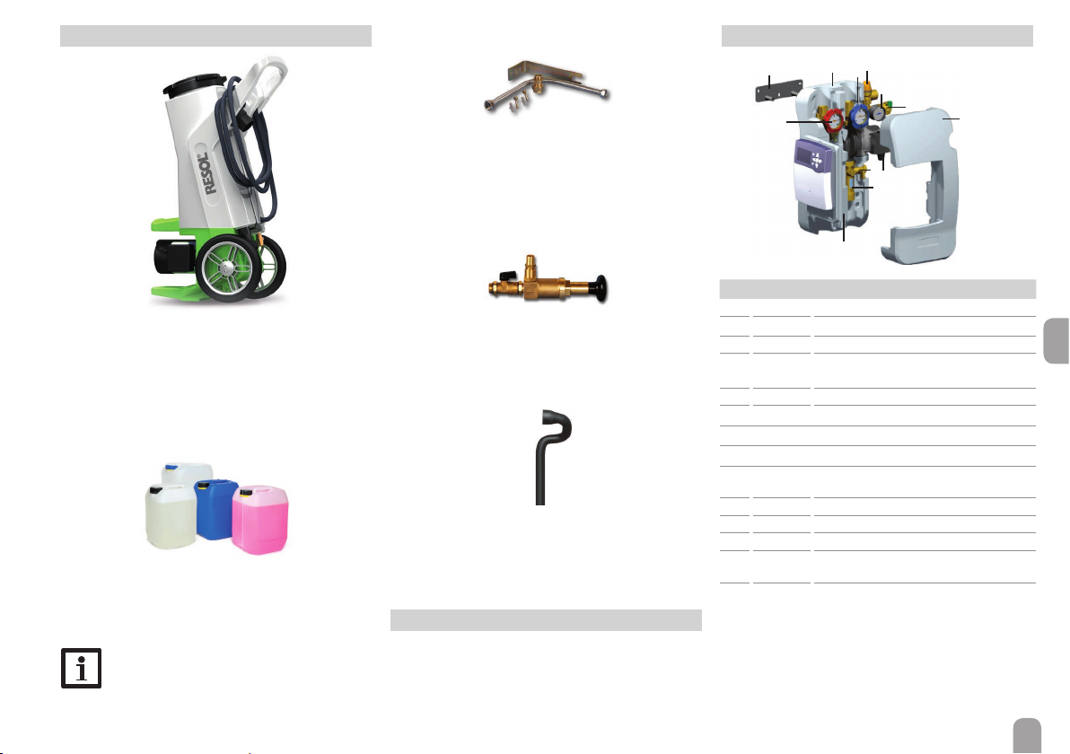
ÎConnect the pressure hose of the filling and flush-
ing station to the fill valve (5) of the pump station.
ÎConnect the flushing hose of the filling and flush-
ing station to the drain valve (3) of the pump sta-
tion.
ÎClose the ball valve of the pump station (4).
ÎOpen the fill valve (5) and the drain valve (3).
ÎSwitch on the filling pump of the filling and flush-
ing station.
ÎFlush the solar thermal system for at least 15
minutes by means of the filling and flushing sta-
tion until the discharged solar fluid is free of gas
bubbles and dirt particles.
ÎDuring flushing, bleed the solar thermal system
several times until the discharged solar fluid (e. g.
Tyfocor®, see chap. 11) is free of air bubbles.
ÎOpen the ball valve of the pump station (4).
After flushing the system
ÎConnect the expansion vessel to the solar ther-
mal system.
ÎClose the drain valve (3) of the pump station
while the filling pump is running.
BAR
ÎIncrease system pressure (approx. 3.5 - 4 bar).The
system pressure can be read from the pressure
gauge.
ÎClose the fill valve (5).
ÎSwitch off the filling pump.
ÎCheck the pressure gauge to see whether the
system pressure reduces and eliminate leaks
where necessary.
ÎSlowly discharge the heat transfer fluid by means
of the drain valve (3) until the operating pressure
is set.
ÎRemove the hoses of the filling and flushing sta-
tion and screw the caps onto the fill and drain
valves. Manually start the solar thermal pump at
maximum speed (see controller manual) and let
the fluid circulate for at least 15 minutes.
ÎBleed the solar thermal system several times.
ÎCheck the system pressure at the pressure gauge.
%
ÎCheck the antifreeze ratio (not required if a
ready-mix is used).
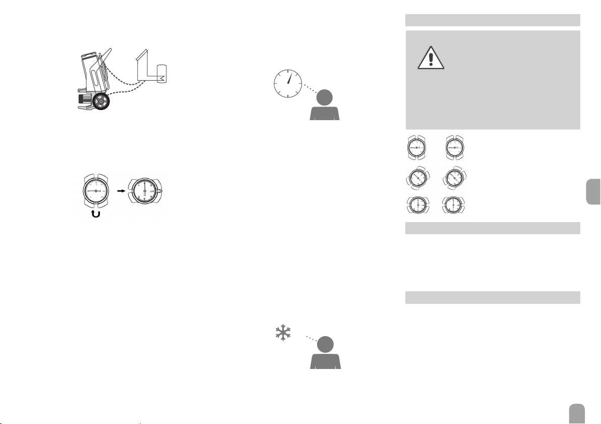
4 Ball valve positions
WARNING! Scald danger! Damage by
overpressure!
When the ball valve is closed, too
high pressure may occur in the
blocked-off line if it is heated.
ÎIn order to prevent scald
danger and damage by
overpressure, make sure
the blocked-off line is not
heated.
Non-return valve in operating
position, fluid flow in flow direc-
tion only.
Ball valve open, fluid flow in both
directions possible.
Ball valve closed, no fluid flow.
5 Draining the system
ÎOpen the ball valve (4).
ÎOpen the air vent at the highest point of the sys-
tem (above the collectors).
ÎOpen the drain valve.
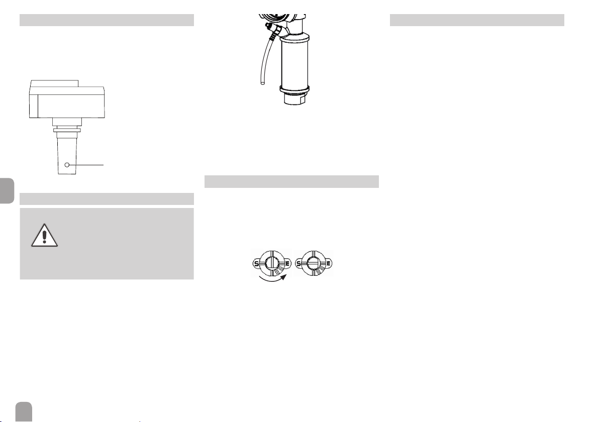
6 Non-return valves
The non-return valves of the pump station are inte-
grated into the ball valves in flow and return and have
an opening pressure of 20 mbar.
In order to completely drain the system, the non-
return valves have to be opened.
ÎFor this purpose, turn the handles of the ball
valves by 45°.
ÎFor normal system operation,open the ball valves
completely.