Resol FlowSol B User manual

*48006770*
48006770
Thank you for buying this RESOL product.
Please read this manual carefully to get the best performance from this unit.
Please keep this manual carefully. www.resol.com
Manual
en
Installation
Operation
Commissioning
Manual for the
specialised craftsman
FlowSol®B/B HE

2
Subject to technical change. Errors excepted.
© 20130912_48006770_FlowSol_B.monen.indd
Safety advice
Please pay attention to the following safety advice
in order to avoid danger and damage to people and
property.
Instructions
Attention must be paid to the valid local standards,
regulations and directives!
Information about the product
Proper usage
The pump station may only be used in the solar cir-
cuit of solar thermal systems in compliance with the
technical data specified in these instructions. Due to
its design the station must be mounted and operated
as described in these instructions!
CE-Declaration of conformity
The product complies with the relevant di-
rectives and is therefore labelled with the
CE mark. The Declaration of Conformity
is available upon request, please contact
RESOL.
Target group
These instructions are exclusively addressed to au-
thorised skilled personnel.
Only qualified electricians should carry out electrical
works.
Initial installation must be effected by qualified per-
sonnel named by the manufacturer.
Contents
1 Overview .................................................... 3
2 Mounting the station................................. 4
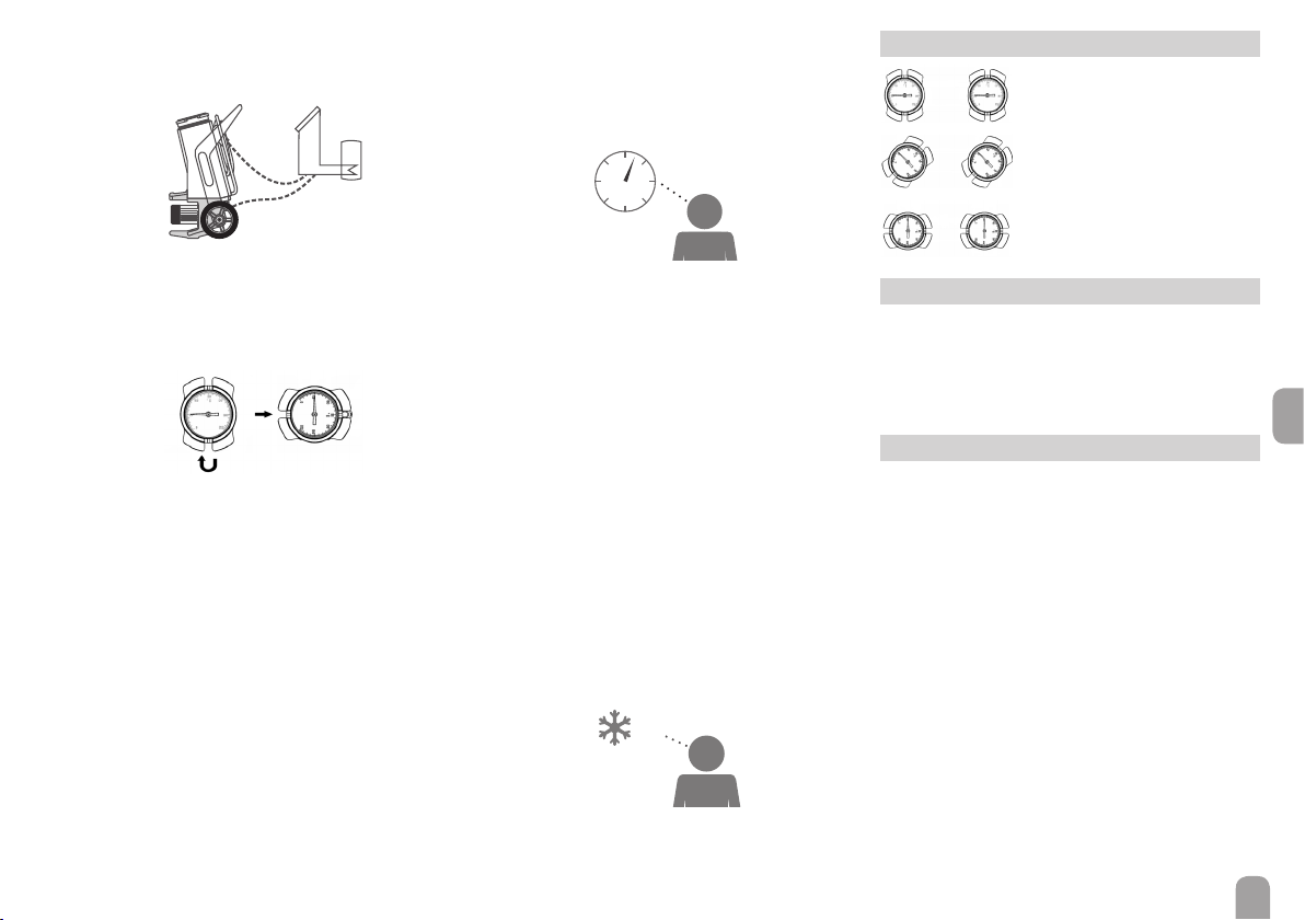
3 Flushing and filling the solar system........ 4
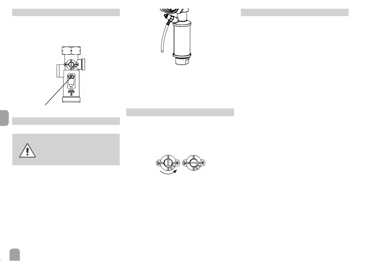
4 Ball valve positions .................................... 5
5 Draining the system .................................. 5
6 Non-return valves...................................... 5
7 Flowmeter.................................................. 6
8 Air separator ............................................. 6
9 Maintenance............................................... 6
10 Safety devices............................................. 6
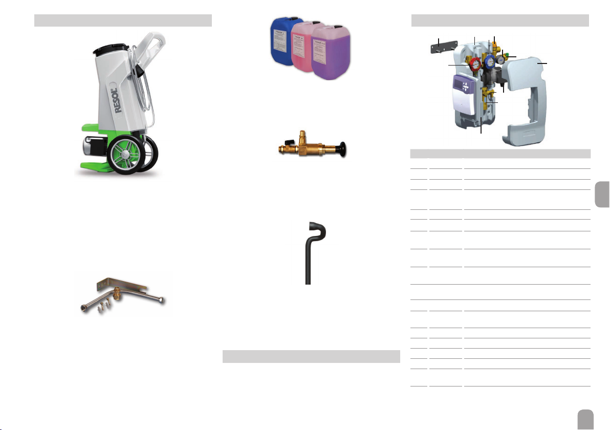
11 Accessories ................................................ 7
12 Information about the pump ................... 7
13 Lists of spare parts ................................... 7
Description of symbols
WARNING! Warnings are indicated with a warn-
ing triangle!
ÎThey contain information
on how to avoid the danger
described.
Signal words describe the danger that may occur,
when it is not avoided.
• WARNING means that injury, possibly life-threat-
ening injury, can occur.
• ATTENTION means that damage to the appli-
ance can occur.
Note
Notes are indicated with an information
symbol.
ÎArrows indicate instruction steps that should be
carried out.
Disposal
• Dispose of the packaging in an environmentally
sound manner.
• Dispose of old appliances in an environmentally
sound manner. Upon request we will take back
your old appliances bought from us and guarantee
an environmentally sound disposal of the devices.
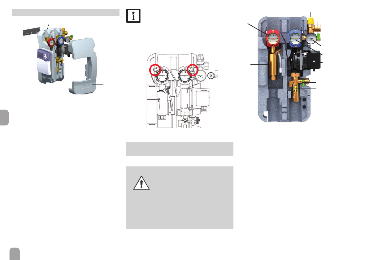
1 Overview
• Pre-assembled twin-line pump station
• Integrated controller of choice from the
DeltaSol®BS, DeltaSol®C,DeltaSol®CS
Plus or DeltaSol®BX series
• Safety assembly with connection for the
diaphragm-type expansion vessel, safety
valve and pressure gauge
• Fill and drain valves
• Wall mounting bracket and mounting material
• Design insulation
• Standard or high-efficiency pump
• Ball valves in flow and return
• Air separator

en
3
FlowSol®B / B HE
Technical data
Circulating pump:
Wilo Star ST 15/6 ECO or 15/7 ECO
Wilo Stratos TEC 15/6 or 15/1-7; WiloYonos Para
ST 15/7 (HE pumps)
Safety valve: 6 bar
Pressure gauge: 0 ... 10 bar
Flowmeter: 1 ... 13 l/min
Non-return valves:
Opening pressure 20 mbar, openable
Connection to diaphragm-type expansion vessel:
¾'' ET, flat sealing
Outlet safety valve: ¾'' IT
Connections to the solar pipes: ¾'' IT
Maximum temperature flow / return:
120 °C / 95 °C
Maximum pressure: 6 bar
Medium: Water with max. 50 % glycol
Dimensions:
Approx. 481 × 320 × 190 mm (with insulation)
Distance centres: 100 mm
Distance centre / wall: 67 mm
Material:
Fittings: brass
Seals: AFM 34
Insulation: EPP foam
Wilo Stratos TEC 15/6 max.
Wilo Stratos TEC 15/7 min.
Wilo Stratos TEC 15/7 max.
Wilo Yonos Para ST 15/7 max.
Wilo Yonos Para ST 15/7 min.
0
1
2
3
4
5
6
7
8
0510 15 20 25 30 35 40 45
0,0
0,1
0,2
0,3
0,4
0,5
0,6
0,7
0,8
Wilo Stratos TEC 15/6 min.
Delivery height (m)
Flow rate (l/min)
Pressure loss (bar)
FlowSol®B
Wilo ST 15/6 ECO max.
W
ilo ST 15/7 ECO max.
0
1
2
3
4
5
6
7
8
0 5 10 15 20 25 30 35 40 45
0,0
0,1
0,2
0,3
0,4
0,5
0,6
0,7
0,8
Delivery height (m)
Flow rate (l/min)
Pressure loss (bar)
FlowSol®B
Pump characteristics / pressure loss characteristics
FlowSol®B standard pumps
FlowSol®B HE high-efficiency pumps

en
4
2 Mounting the station
10
11
12
13
10 Wall mounting bracket
11 Back half of the insulation
12 Front half of the insulation
13 Hinged controller panel
Controller and controller panel depend on the ver-
sion of the station
ÎDetermine the mounting site of the station.
ÎMark the drill holes by means of the template en-
closed, then drill and insert wall plugs (see figure
to the right).
ÎTake the station out of the packaging.
ÎRemove the front half of the insulation. Leave the
pump station attached to the back half of the in-
sulation!
ÎFasten the pump station to the wall with the en-
closed screws. For this purpose, use a crosshead
screw driver.
ÎFold the hinged controller panel to the left.
ÎConnect the pipework between pump station
and store and collector respectively.
Note
All connections are already tightened such
that they usually do not have to be tightened
again. However, during commissioning of the
system all connections have to be checked
for leaks (pressure test).
3 Flushing and filling the solar
system
WARNING! Scald danger!
Pressure surge damage!
If the medium enters strongly heat-
ed, empty collectors, pressure surg-
es caused by evaporation can occur.
ÎIn order to prevent the solar
fluid from vaporising inside
the collectors, do not fill
or flush the system during
times of strong irradiation!
1 Safety valve
2 Pressure gauge
3 Drain valve
4 Ball valve (return) with thermometer and
integrated non-return valve
5 Fill valve
6 Pump
7 Flowmeter
8 Ball valve (flow) with thermometer and
integrated non-return valve
9 Air separator
5
4
3
1
2
6
7
9
8

en
5
Before flushing the system
ÎDisconnect the expansion vessel from the solar
thermal system.
2.
ÎConnect the pressure hose of the filling and flush-
ing station to the fill valve (5) of the pump station.
ÎConnect the flushing hose of the filling and flush-
ing station to the drain valve (3) of the pump sta-
tion.
ÎClose the ball valve of the pump station (4).
ÎOpen the fill valve (5) and the drain valve (3).
ÎSwitch on the filling pump of the filling and flush-
ing station.
ÎFlush the solar thermal system for at least 15
minutes by means of the filling and flushing sta-
tion until the discharged solar fluid is free of gas
bubbles and dirt particles.
ÎDuring flushing, bleed the solar thermal system
several times until the discharged solar fluid (e. g.
Tyfocor®, see chap. 11) is free of air bubbles.
ÎOpen the ball valve of the pump station (4).
After flushing the system
ÎConnect the expansion vessel to the solar ther-
mal system
ÎClose the drain valve (3) of the pump station
while the filling pump is running.
BAR
ÎIncrease system pressure (approx. 3.5 - 4 bar).The
system pressure can be read from the pressure
gauge.
ÎClose the fill valve (5).
ÎSwitch off the filling pump.
ÎCheck the pressure gauge to see whether the
system pressure reduces and eliminate leaks
where necessary.
ÎSlowly discharge the heat transfer fluid by means
of the drain valve (3) until the operating pressure
is set.
ÎRemove the hoses of the filling and flushing sta-
tion and screw the caps onto the fill and drain
valves. Manually start the solar thermal pump at
maximum speed (see controller manual) and let
the fluid circulate for at least 15 minutes.
ÎBleed the solar thermal system several times.
ÎCheck the system pressure at the pressure gauge.
11.
%
ÎCheck the antifreeze ratio (not required if a
ready-mix is used).
4 Ball valve positions
Non-return valve in operating
position, fluid flow in flow direc-
tion only
Ball valve open, fluid flow in both
directions possible
Ball valve closed, no fluid flow
5 Draining the system
ÎOpen the ball valve (4).
ÎOpen the air vent at the highest point of the sys-
tem (above the collectors).
ÎOpen the drain valve.
6 Non-return valves
The non-return valves of the pump station are inte-
grated into the ball valves in flow and return and have
an opening pressure of 20 mbar.
In order to completely drain the system, the non-
return valves have to be opened.
ÎFor this purpose, turn the handles of the ball
valves by 45°.
ÎFor normal system operation,open the ball valves
completely.

en
6
7 Flowmeter
The flowmeter measures and indicates the flow rate
with a range of 1-10 l/min. For the device to function
faultlessly, the system must be flushed and free of grit.
Read the flow rate from the upper edge of the float
8 Air separator
WARNING! Scald danger!
During venting, the air discharged
can reach temperatures of more
than 100 °C.
The air separator is used for venting the water/ glycol
mixture in the solar circuit.The air separated from the
heat transfer fluid gathers in the air scoop and can be
discharged manually at the air vent valve.
ÎOpen the air vent valve and collect the discharged
fluid in a suitable container.
ÎCheck the system pressure after bleeding and, if
necessary, increase it to the specified operating
pressure.
9 Maintenance
In the case of maintenance (such as a replacement of
the pump) proceed as follows:
ÎClose the ball valve (4).
ÎTurn the slot of the flowmeter spindle by 90°
anti-clockwise (see figure below).
The heat transfer fluid can now be drained from the
pump.
ÎOpen the drain valve (3).
If necessary, open the union nut at the pressure side.
ÎNow dismount the pump.
10 Safety devices
The pump station is equipped with a diaphragm safety
valve which corresponds to the relevant directives
and regulations. For installation and operation, please
pay attention to the following advice:
• The safety valve has to be easily accessible.The ef-
ficiency of the valve must not be influenced or disa-
bled by barriers!
• The strainer or other restriction devices must not
be mounted between collector (-field) and safety
valve!
• The diameter of the discharge pipe must cor-
respond to the diameter of the valve outlet; the
maximum length must not exceed 2 m; more than
2 bends are inadmissible. When these values are
exceeded, you have to install a discharge pipe with
larger dimensions. Do not use more than 3 bends
and pipes longer than 4 m!
• If the discharge pipe leads into a drain pipe with a
funnel, the diameter of the drain pipe has to be at
least twice as large as the valve inlet.The opening of
the discharge pipe must be inclined downwards. It
must be routed such that the opening can be seen
but does not present any risk to a person standing
or passing by.
• We recommend placing a container below the dis-
charge pipe. If the safety valve opens, the fluid will
be collected and can be refilled into the system
when the pressure is too low.

en
7
Heat transfer and cleaning fluids
In our product portfolio, you will find a range of heat
transfer fluids for different applications, available as
readymix or concentrate, as well as cleaning fluids.
Filling and injection pump
Filling and injection pump with non-return valve for
pressure increase and refilling of heat transfer fluids.
½" OT self-sealing with O-ring, 15mm tube connec-
tion. Pump output 2 l/min, 4.5 bar max.
Article no: 280 005 40
ALS15 discharge hose
1.5 m hose for connection to the safety valve of the
FlowSol® Bpump station.
Article no: 280 004 92
See our full range of accessories on our website:
www.resol.com
12 Information about the pump
Depending on the version, the station is equipped
with different pumps. Data concerning the pump in
your station are available at the pump manufacturer
under www.wilointec.com. Upon request we will
provide you with further information.
11 Accessories
SBS 2000 filling and flushing station
The SBS 2000 has been especially designed for pro-
fessionally filling and flushing solar thermal and heat-
ing systems. Its many thought-out details facilitate
transport, operation and cleaning, the attractive de-
sign makes it the ideal companion for a professional
performance.
Article no: 280 010 93
Wall mounting for diaphragm-type expansion
vessel
Wall mounting for diaphragm-type expansion vessel
with screws and wall plugs, high grade steel corru-
gated tube and connection thread ¾". Including quick
release valve coupling enabling removal of expansion
without draining down of the system.
Article no: 280 004 60
13 Lists of spare parts
12a,b
2
5
1
6a-d
7
8
10 11 4
13
3
Pos. Art. no. Article
1 11200054 Safety valve 6 bar
2 11200039 Pressure gauge
3 11200058 Fill / Drain valve
4 11200069 Ball valve (return) with thermometer and
integrated non-return valve
5 11200058 Fill / Drain valve
6a 28000099 Pump WILO ST15/6
6b or
28000109 Pump WILO ST15/7
6c or
63300152
Pump WILO Stratos TEC 15/6
(HE pump)
6d or
11201176
Pump WILO Stratos TEC 15/7
(HE pump)
6e or
11204195
Pump WILO Yonos Para ST 15/7
(HE pump)
7 28000490 Flowmeter
8 11200062 Ball valve (flow) with thermometer and
integrated non-return valve
9 28000491 Air separator (not shown)
10 11200071 Wall mounting bracket
11 70001512 Back half of the insulation
12a 70001614 Front half of the insulation DeltaSol®BX
12b or
70001613
Front half of the insulation DeltaSol®
B / C / CS Plus (not shown)
13 70001612 Hinged controller panel

Distributed by: RESOL – Elektronische Regelungen GmbH
Heiskampstraße 10
45527 Hattingen / Germany
Tel.: +49 (0) 23 24 / 96 48 - 0
Fax: +49 (0) 23 24 / 96 48 - 755
www.resol.com
Important note
The texts and drawings in this manual are correct to the best of our knowledge. As
faults can never be excluded, please note:
Your own calculations and plans, under consideration of the current standards and
directions should only be basis for your projects.We do not offer a guarantee for
the completeness of the drawings and texts of this manual - they only represent
some examples.They can only be used at your own risk. No liability is assumed for
incorrect, incomplete or false information and / or the resulting damages.
Note
The design and the specifications can be changed without notice.
The illustrations may differ from the original product.
Imprint
This mounting- and operation manual including all parts is copyrighted. Another
use outside the copyright requires the approval of RESOL – Elektronische Rege-
lungen GmbH. This especially applies for copies, translations, micro films and the
storage into electronic systems.
Editor: RESOL – Elektronische Regelungen GmbH
Other manuals for FlowSol B
2
This manual suits for next models
1
Table of contents
Other Resol Water Pump manuals
Popular Water Pump manuals by other brands

Pentair
Pentair AURORA 3310 INSTRUCTION, INSTALLATION, MAINTENANCE AND REPAIR MANUAL

IML
IML BIG DISCOVERY Installation and maintenance manual

Champion Pump
Champion Pump CPES5 Installation and operation manual

Nordson
Nordson EP2 manual

Meec tools
Meec tools 015272 operating instructions

Drieaz
Drieaz S262 Replacement