Restar solar RT Series User manual

www.restarsolar.com
1
INSTALLATION MANUAL FOR STANARD MODULE
1.0 GENERAL INFORMATION
1.1 INSTALLATION MANUAL DISCLAIMER
1.2 LIMITATION OF LIABILITY
2.0 SAFETY PRECAUTIONS
3.0 MECHANICAL / ELECTRICAL SPECIFICATIONS
4.0 UNPACKING AND STORAGE
5.0 MODULE INSTALLATION
5.1 MODULE WIRING
5.2 EQUIPMENT GROUNDING
6.0 MOUNTING INSTRUCTIONS
6.1 MOUNTING METHOD: BOLTING
7.0 MAINTENANCE
GENERAL INFORMATION

www.restarsolar.com
2
This general manual provides important safety information relating to the installation, maintenance and handling of RT-series
solar modules. Professional installer must read these guidelines carefully and strictly follow these instructions.
Failure to follow these instructions may result in death, injury or property damage. The installation and handling of PV modules
requires professional skills and should only be performed by qualified professionals. The installers must inform end -users
(consumers) the aforesaid information accordingly.
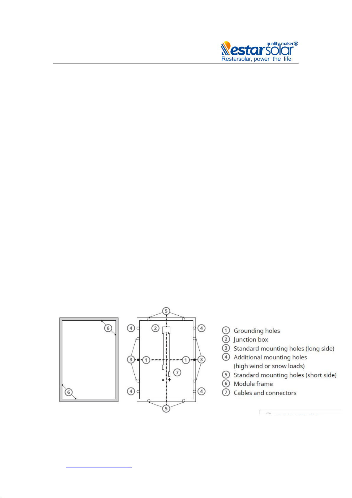
The word "module" or "PV module" used in this manual refers to one or more RT-series solar modules.
Please retain this manual for future reference. We recommend checking www.restarsolar.com regularly for the most
updated version.
1.1
INSTALLATION MANUAL DISCLAIMER
The information contained in this manual is subject to change by Restar Solar Renewable Energy Co.,Ltd without prior notice. Restar
Solar Renewable Energy Co.,Ltd gives no warranty of any kind whatsoever, either explicitly or implicitly, with respect to the information
contained herein.
1.2
LIMITATION OF LIABILITY
Restar Solar Renewable Energy Co.,Ltd shall not be held responsible for damages of any kind, including – without limitation – bodily
harm, injury or damage to property, in connection with handling PV modules, system installation, or compliance or non-compliance with
the instructions set forth in this manual.
2.0
SAFETY PRECAUTIONS
Warning
Before attempting to install, wire, operate and/or service the module and other electrical equipment, all instructions should be
read and understood.
PV module inter connectors pass direct current (DC) when exposed to sunlight or other light sources.
Contact with electrically active parts of the module, such as terminals, can result in injury or death, irrespective of whether or not
the module and the other electrical equipment have been connected.
GENERAL SAFETY
· All installation work must comply with applicable regional and local regulations or other national or international electrical
standards.
Protective clothing (non-slip gloves, clothes, etc.) must be worn during installation to prevent direct contact with 30 V DC or
greater, and to protect your hands against sharp edges.
Prior to installation, remove all metallic jewelry to prevent accidental exposure to live circuits.
When installing or handling modules in light rain, morning dew or strong wind, appropriate safety measures should be taken to
avoid damaging the modules or injuring people.
Do not allow children or unauthorized persons near the installation site or storage area of modules.
Use electrically insulated tools to reduce the risk of electric shock.
If the disconnects and OCPD's cannot be opened or the inverter can not be powered down, cover the fronts of modules in the
PV array with an opaque material to stop the production of electricity when installing or working on a module or wiring.
·Do not use or install broken modules.
· Contact with module surfaces or frames may cause electric shock if the front glass is broken or the back sheet is torn.
· The PV module does not contain any serviceable parts. Do not attempt to repair any part of the module.
· Keep the junction box cover closed at all times.
·Do not disassemble a module or remove any module part.
Do not artificially concentrate sunlight on a module.
·Do not connect or disconnect modules when current from the modules or an external source is present.

www.restarsolar.com
3
3.0
MECHANICAL / ELECTRICAL
SPECIFICATIONS
Module electrical ratings are measured under Standard Test Conditions (STC) of 1000 W/m2 irradiance, with an
AM1.5 spectrum, and a cell temperature of 25°C. Detailed electrical and mechanical characteristics of Restar
Solar Renewable Energy Co.,Ltd crystalline silicon PV modules specifications can be found on
www.restarsolar.com Main electrical characteristics under STC are also stated on each module label. The
maximum system voltage for all module series is stated on data sheet.
Under certain conditions, a module may produce more current or voltage than under its Standard Test
Condition's rated power. As a result, the module short-circuit current at under STC should be multiplied by 1.25,
and a correction factor should be applied to the open-circuit voltage when determining component ratings and
capacities. Depending on your local regulations, an additional 1.25 multiplier for the short-circuit current (giving
a total multiplier of 1.56) may be applicable when sizing conductors and fuses.
4.0
UNPACKING AND STORAGE
PRECAUTIONS AND GENERAL SAFETY
· If modules are stored in an uncontrolled environment for less than 3 months, extra precautions should be
taken to prevent moisture exposure to connectors or sunlight exposure to modules.
· Unpack module pallets carefully, following the steps shown on the pallet. Unpack, transport and store the
modules with care.
Modules must always be unpacked by two people. Always use both hands when handling modules
Do not stand, step, walk and/or jump on modules
Stacks of modules should contain no more than 12 modules, and the frames should be
aligned.
·Do not place excessive loads on the module or twist the module frame.
·Do not use sharp instruments on the modules. Particular care should be taken to avoid module back sheets

www.restarsolar.com
4
being damaged by sharp objects, as scratches may directly affect product safety.
·Do not leave modules unsupported or unsecured.
·Do not change the wiring of bypass diodes.
· Keep all electrical contacts clean and dry.
PRODUCT IDENTIFICATION
· Each module is equipped with two identical bar codes (one inside the laminate under the front glass, the
second on the rear side of the module) that act as a unique identifier. Each module has a unique serial
number containing 13 (pre March 2013) or 14 (post March 2013) digits.
· A nameplate is also affixed to the rear of each module. This nameplate specifies the model type, as well as
the main electrical and safety characteristics of the module.
5.0
MODULE INSTALLATION
PRECAUTIONS MEASURES AND GENERAL SAFETY
· Prior to installing modules please obtain information about any requirements and necessary approvals for the
site, installation and inspection from the relevant authorities.
· Check applicable building codes to ensure that the construction or structure (roof, facade, support, etc.) can
bear the module system load.
·
RT-series solar modules have been qualified for Application Class A (equivalent to Safety Class II
requirements). Modules rated under this class should be used in systems operating at voltage above 50 V or
power above 240 W, where general contact access is anticipated.
· When installing modules, please ensure the supporting roof has a fire resistant roof covering rated for the
application.
· The fire rating for this module is only valid when the product is installed as specified in the mechanical
mounting instructions.
DO NOT STAND OR STEP on the modules under any circumstances.
Localized heavy loads may cause severe micro-cracks at cell level, which in turn may compromise module
reliability.
ENVIRONMENTAL CONDITIONS
· The module is intended for use in general open-air climates, environmental conditions appearing in nature
Temperature and humidity.
·
Please consult the Restar Solar Renewable Energy Co.,Ltd technical support department for more
information on the use of modules in special climates.
Do not install modules near naked flames or flammable materials.
Do not immerse modules in water or constantly expose modules to water (either fresh or salt) (i.e. from
fountains, sea spray).
· Exposing modules to salt (i.e. marine environments) or sulfur (i.e. sulfur sources, volcanoes) incurs the risk of
module corrosion.
INSTALLATION REQUIREMENTS
· Ensure that the module meets the general technical system requirements.
· Ensure that other system components do not damage the module mechanically or electrically.

www.restarsolar.com
5
· Modules can be wired in series to increase voltage or in parallel to increase current. To connect modules in
series, connect the cables from the positive terminal of one module to the negative terminal of the next
module. To connect in parallel, connect the cables from the positive terminal of one module to the positive
terminal on the next module.
· The quantity of bypass diodes in the module's junction box may vary depending on the model series.
· Only connect the quantity of modules that corresponds to the voltage specifications of the inverters used in
the system. Modules must not be connected together to create a voltage higher than the maximum permitted
system voltage, even under the worst local temperature conditions (see Table 1 for the correction coefficients
that apply to open-circuit voltage).
· A maximum of two strings can be connected in parallel without the need to incorporate an over-current
protection device (fuses, etc.) in series within each string. Three or more strings can be connected in parallel if
an appropriate, certified over-current protection device is installed in series within each string.
Only modules with similar electrical outputs should be connected in the same string to avoid
or minimize mismatch effects in arrays.
· To minimize risk in the event of an indirect lightning strike, avoid forming loops when designing the system.
· The recommended maximum series fuse rating is stated in a table in the Annex.
· Modules should be safely fixed to bear all expected loads, including wind and snow loads. A minimum
clearance of 6.5 mm (0.25 in) between modules is required to allow for thermal expansion of the frame.
The small drainage holes on the underside of the module must not be blocked.
OPTIMUM ORIENTATION AND TILT
· To maximize your annual yield, find out the optimum orientation and tilt for PV modules in your region. The
highest yields are achieved when sunlight shines perpendicularly onto the PV modules.
AVOID SHADING
· Even minor partial shading (e.g. from dirt deposits) reduces yields. A module can be considered to be
unshaded if its entire surface is free from shading all year round. Sunlight should be able to reach the module
even on the shortest day of the year.
RELIABLE VENTILATION
· Sufficient clearance (at least 10 cm (3.94 in)) between the module frame and the mounting surface is required
to allow cooling air to circulate around the back of the module. This also enables condensation or moisture to
dissipate.
5.1
MODULE WIRING
CORRECT WIRING SCHEME
· Ensure that the wiring is correct before starting up the system. If the measured open circuit voltage (Voc) and
short-circuit current (Isc) differ substantially from the specifications, this indicates that there is a wiring fault.
CORRECT CONNECTION OF PLUG CONNECTORS
· Make sure that connections are safe and tight. Plug connector should not be subjected to stress from the
exterior. Connectors should only be used to connect the circuit. They should never be used to turn the circuit on

www.restarsolar.com
6
and off.
USE OF SUITABLE MATERIALS
· Only use dedicated solar cable and suitable plugs (wiring should be sheathed in a sunlight-resistant
conduit or, if exposed, should be sunlight-resistant itself) that meet local fire, building and electrical
regulations. Please ensure that all wiring is in perfect electrical and mechanical condition.
· Installers may only use single conductor, 2.5-10 mm2(8-14 AWG), 90°C wet rated solar cable, with proper
insulation that is able to withstand the maximum possible system open-circuit voltage . Only copper conductor
material should be used. Select a suitable conductor gauge to minimize voltage drop.
CABLE PROTECTION
Secure the cables to the mounting system using UV-resistant cable ties. Protect exposed cables from damage
by taking appropriate precautions (e.g. placing them inside a plastic conduit). Avoid exposure to direct sunlight.
A minimum bending radius of 60 mm (2.36 in) is required when securing the junction box cables to the racking
system.
6.0 GROUNDING
· we recommend that they be grounded and that module installation should comply with all local electrical
codes and regulations.
· Grounding connections should be installed by a qualified electrician.
·
Connect module frames together using adequate grounding cables: Restar Solar recommends using
4-14mm² copper wire. Holes provided for this purpose are identified with a green label. All conductive
connection junctions must be firmly fixed.
All bolts, nuts, flat washers, lock washers and other relevant hardware should be made of stainless steel,
unless otherwise specified.
·
Restar Solar Renewable Energy Co.,Ltd does not provide ground hardware.
The mounting design must be certified by a registered professional engineer. The mounting design and
procedures must comply with local codes and requirements from all relevant authorities.
·
Restar Solar does not provide mounting hardware.

www.restarsolar.com
7
· Standard modules can be mounted onto a support structure using one of several approved methods.
One such method is described below.
Use appropriate corrosion-proof fastening materials. All mounting hardware (bolts, spring washers, flat
washers, nuts) should be stainless steel.
· Use a torque wrench for installation.
·Do not drill additional holes or modify the module frame. Doing so will void the warranty.
· Standard modules can be installed in either landscape or portrait orientations. Refer to the detailed
instructions for further guidance. Please note that in areas with heavy snowfall (> 2400 Pa) further
countermeasures such as the use of additional support bars should be considered to avoid snow loads
damaging the lowest row of modules.
6.1
MOUNTING METHOD: BOLTING
· Modules should be bolted to support structures through the mounting holes in the rear frame flanges only.
·Each module must be securely fastened at a minimum of 4 points on two opposite sides, using the innermost
mounting holes. M6 size bolt and nut shall be used for bolting method. Tightening torques should be within 4 ~ 6 Nm
(3.0-4.4 ft-lbs) for M6x1 coarse thread bolts, depending on bolt class. In areas with heavy wind loads, additional
mounting points should be used. The system designer and the installer are responsible for calculating the loads and
ensuring that the support structure meets the requirements.
Mounting method: Bolting
· Modules should be bolted at the following hole locations depending on the configuration and load:
Table 2: Approved bolting methods

www.restarsolar.com
8
7.0
MAINTENANCE
Do not make modifications to the PV components (diode, junction box, plug connectors).
· Regular maintenance is required to keep modules clear of snow, bird droppings, seeds, pollen, leaves,
branches, dirt spots, and dust.
· Modules with sufficient tilt (at least 15°), generally do
not require cleaning (rain will have a self-cleaning effect). If the module has become soiled, it shall be washed
with water and a non-abrasive cleaning implement (sponge) during the cool part of the day. Do not scrape or
rub dry dirt away, as this may cause micro scratches.
· Snow should be removed using a soft brush.
· The system shall be periodically inspected to verify
the integrity of all wiring and supports.
· To protect against electric shock or injury, electrical or mechanical inspections and maintenance should be
performed by qualified personnel only and on a regular basis.
Table of contents
Popular Solar Panel manuals by other brands

Clenergy
Clenergy PV-ezRack SolarTerraceIII-A Planning and installation

Powereco
Powereco PE-PLK-120WPX20A manual

PulseTech
PulseTech SP-12-OBD-A installation manual

Giacomini
Giacomini R557 Instruction

TSI Instruments
TSI Instruments 8145-SO Operation and maintenance manual

Sunerg Solar Energy
Sunerg Solar Energy TWIN+ installation manual