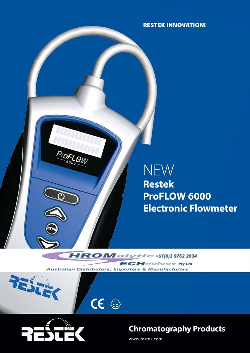
Restek ProFLOW 6000 User manual

www.restek.com
Restek’s
ProFLOW 6000
Electronic Flowmeter
User Manual
Version 5.6
for cat.# 22656

No part of this manual may be reproduced in any form or by any means without the prior agreement or permission by Restek Corporation.
The ProFLOW 6000
volumetric flowmeter.
Table of Contents Page
1.0 Introduction ............................................................................................................. 3
2.0 Specifications........................................................................................................... 3
3.0 Installing the batteries........................................................................................... 4
4.0 Battery power consumption ................................................................................. 4
4.1 Battery lifetime ................................................................................................ 4
4.2 Battery charge indicator ................................................................................ 4
5.0 Operating instructions ........................................................................................... 5
6.0 Interpreting results................................................................................................. 6
6.1 Flow range display.......................................................................................... 6
7.0 Data collection on the PC...................................................................................... 7
8.0 ProFLOW 6000 menu structure............................................................................. 9
8.1 Unit power up/power down.......................................................................... 9
8.2 USB activation................................................................................................ 10
8.3 Adjust LCD image backlight........................................................................ 10
8.4 Show battery charge indicator ................................................................... 11
8.5 Firmware version information .................................................................... 11
8.6 Adjust auto shutoff duration ...................................................................... 12
8.7 Display calibration date ............................................................................... 12
8.8 Display unit serial number .......................................................................... 13
9.0 Troubleshooting.................................................................................................... 13
10.0 Product back label legend................................................................................... 14
11.0 Volumetric vs. mass flow measurements.......................................................... 15
12.0 Bubble flowmeters................................................................................................ 15
13.0 Product case specifications................................................................................. 16
14.0 Calibration and service ........................................................................................ 16
Declaration of Conformity................................................................................... 33

www.restek.com
- 3 -
1.0 Introduction
Restek’s ProFLOW 6000 Flowmeter is specifically designed for use with gas chromatography (GC) systems. The probe is applied directly to the
gas flow stream and the measured flow rate is presented on the LCD screen. Units of flow are measured in mL/min.
This unit provides continuous real-time measurements of gas streams ranging from 0.50 mL/min to 500 mL/min. Because the technology uses
volumetric flow measurement, the unit is compatible with all laboratory gases.
CAUTION: Do NOT exceed maximum operating flow rates.
Recalibration may be required if the unit has been
subjected to extreme flow rates.
Always use appropriate laboratory safety practices when
operating this device. Wear laboratory safety goggles when
operating this unit.
NOTE: There are no serviceable parts in this unit. Opening the
device—other than to change the batteries—or tampering with the
internal parts will void the factory warranty.
NOTE: To ensure accurate measurements and effective clearance of
the flow gas from the unit, DO NOT obstruct the vent holes on the
back of the unit.
NOTE: Modifying the length of tubing can cause a shift in calibration.
2.0 Specifications
Table I:
Type of measurement Volumetric flow
Accuracy of measurements ± 2% of flow reading or ± 0.2 mL/min, whichever is greater
Power requirements 2 AA alkaline batteries 1.5 V DC each/3 V DC 200 ma
Operating flow range 0.50 to 500 mL/min
Operating temperature range 32 °-120 °F (0 °- 48 °C)
Available communication USB data port
Warranty One year
Calibration NIST traceable
Yearly recalibration is recommended
Certifications CE, Ex (see section 10.0)
Compliance WEEE, RoHS 2, China RoHS 2 (see section 10.0)
Figure 1: Product diagrams
BACK
FRONT

3.0 Installing the batteries
This unit uses two AA alkaline batteries.
To install batteries, extend the wire stand. Open the
cover. Insert the batteries with the polarity ( and )
correctly aligned. Close the cover. (Figures 2 and 3.)
Precautions for battery replacement:
• Load the new batteries with their polarity ( and ) aligned correctly.
• Do not use rechargeable batteries.
4.0 Battery power consumption
4.1 Battery lifetime
The battery lifetime is dependent on the number of options the user
has enabled.
The unit is shipped with the most energy-demanding options disabled
(Table II).
The power saving functions can be changed.
è See Section 8.2: USB Activation
è See Section 8.3: Adjust LCD Image Backlight
è See Section 8.6: Adjust Auto Shutoff Duration
4.2 Battery charge indicator
The unit includes a battery charge indicator. Replace batteries as
needed.
è See Section 8.4: Show Battery Charge Indicator
Auto shutoff duration 6 minutes
LCD backlight 0 (off)
USB port disabled
NOTE: Store your ProFLOW 6000 in its protective storage case
following use. Do not store this manual or any other items on top
of the ProFLOW 6000 or the unit may turn on when the storage case
lid is closed.
Table II: Default settings for the ProFLOW 6000
Figure 2: Extend the wire stand
before opening battery door.
Figure 3
Insert the batteries
as marked.
+
–+
–
+–
+–
- 4 -
www.restek.com

www.restek.com
- 5 -
5.0 Operating instructions
CAUTION: Do not exceed maximum operating flow rates.
Recalibration may be required if the unit has been sub-
jected to extreme flow rates.
Connect the white probe end tip to the output of the gas flow line to
be measured. Be sure the probe tip connection is completely sealed
around the flow source outlet and is free of leaks (Figure 4). (White
tubing ID 0.125"; OD 0.250")
Press and hold the (Power) button until the unit responds
with a regular clicking sound. The ProFLOW will immediately begin
to provide flow measurements (Figure 5). Wait for the measured
values to stabilize. It takes a few seconds for the unit to reach a steady
state with the gas flow line.
To power down the unit, press and hold the (Power) button
until the unit stops clicking.
The unit is equipped with a timed auto shutoff option. (Default: 6
minutes.)
è See Section 8.6: Adjust Auto Shutoff Duration
Figure 4: Probe connected to a GC gas outlet.
Figure 5: LED displays the measured flow value.

- 6 -
www.restek.com
6.0 Interpreting results
The unit has an operating range of 0.50 mL/min to 500 mL/min (Figure 7). If the flow is less than
0.50 mL/min., the display will read “under range.”
If the flow exceeds 515 mL/min, the display will read “over range.” Excessively high flow rates may dam-
age this unit.
NOTE: units of mL/min are equivalent to ccm.
6.1 Flow range display
The unit automatically adjusts the resolution of the display depending on the flow range being measured.
Table III shows the resolution of the flow ranges.
Figure 6: Example flow
value.
Figure 7: Description of flow ranges.
Flow range Display resolution (mL/min)
0.50 – 9.99 0.01
10.0 – 99.9 0.1
100 – 500 1
Table III: Display resolution vs. flow range.
Flow Range
Display reads
“under range”
Display reads
flow values
Display reads
“over range”
0.50 mL/min 515 mL/min

www.restek.com
- 7 -
7.0 Data collection on the PC
WARNING: ONLY connect USB cable to USB port
while unit is OFF.
The ProFLOW 6000 provides you with a data stream of real-time
flow values via the USB port (Figure 1, p. 3). In order to use this
feature, you must first install the appropriate FTDI Virtual Com
Port (VCP) Driver available at:
http://www.ftdichip.com/Drivers/VCP.htm
The VCP driver will cause the ProFLOW to appear as a standard
RS-232 port. This will work on any operating system for which
there is an FTDI VCP driver. After installing the driver, connecting
the device, and determining which port it creates, you can access
the data stream through any programmatic means, or by using any
serial terminal software.
For Windows systems:
To determine which port the ProFLOW is using, go to the Control
Panel and open System. Go to the Hardware tab and click the Device
Manager button. Expand the Ports (COM & LPT) entry. Make sure
the VCP driver is installed, and then connect a powered ProFLOW
6000 to the USB port. You will see the new COM port appear. Open
your serial terminal.
è See Section 8.2: USB Activation
Figure 8: Screen capture of data collection.

- 8 -
www.restek.com
If you do not already have serial terminal software, free,
open-source options are available online (i.e., RealTerm, etc.).
You can download RealTerm* software from:
http://realterm.sourceforge.net/
After installation, click the Port tab and set the following:
Baud: 115200
Port: The appropriate VCP for your ProFLOW
Parity: None
Data Bits: 8 bits
Stop Bits: 1 bit
HardwareFlow Control: None
Go to the USB menu entry in the ProFLOW and turn the
transmission on. Finally, click Open on the Port tab in RealTerm
and you will see the serial data stream begin in the terminal window
(Figure 8).
If you would like to log the flow data, this can be done by clicking
on the Capture tab. Set File to the name and location of the log file
that you would like to save and click either the Start: Overwrite or
Start: Append buttons appropriately (Figure 9).
*This software is not supplied or supported by Restek. User assumes all responsibility for the
downloading and use of the program.
Figure 9: Screen capture of data collection.

www.restek.com
- 9 -
8.0 ProFLOW 6000 menu structure
8.1 Unit power up/power down
Press the (Power) button:
The LCD screen will display Followed by
the device intro screen: calibrated date:
To power off, press and hold the (Power) button.
Other messages encountered at power up
If the unit is hooked up to a flow stream
with a flow rate less than 0.50 mL/min, the
unit will report an “under range” status for
the flow. This message will appear until the
flow rate exceeds 0.50 mL/min.
Followed by measured
flow data:
01/10/2012

- 10 -
www.restek.com
8.2 USB activation
To enable the USB, press the (Menu) button.
Use the (arrow) keys to select the USB menu:
Press the (menu) button again to enter the value select
screen.
Use the (arrow) keys to toggle between USB “on” and “off.”
To return to the main menu screen, press the (menu)
button.
To exit and return to measuring flow, press the (menu)
button again.
è See Section 7.0: Data Collection on the PC
8.3 Adjust LCD image backlight
Press the (Menu) button.
Use the (arrow) keys to select the Backlight menu:
Press the (Menu) button again to enter the value select
screen.
Use the (arrow) keys to select the backlight value.
Backlight Values: 0 (off) and 5 (maximum).
To return to the main menu screen, press the (Menu)
button.
To exit and return to measuring flow, press the (Menu)
button again.

www.restek.com
- 11 -
8.4 Show battery charge indicator
Press the (Menu) button.
Use the (arrow) keys to select the Batteries menu:
Press the (Menu) button again.
The battery life is displayed.
To return to the main menu screen, press the (Menu)
button.
To exit and return to measuring flow, press the (Menu)
button again.
8.5 Firmware version information
Press the (Menu) button.
Use the (arrow) keys to select the Firmware menu:
Press the (Menu) button again.
The most recent version of firmware is displayed.
To return to the main menu screen, press the (Menu)
button.
To exit and return to measuring flow, press the (Menu)
button again.

- 12 -
www.restek.com
8.6 Adjust auto shutoff duration
To conserve battery life, the unit automatically turns off after
6 minutes. To customize the auto shutoff setting, press the
(Menu) button.
Use the (arrow) keys to select the Power Time menu:
Press the (Menu) button again to enter the value select
screen.
Use the (arrow) keys to select the auto shutoff setting.
Values: 1–59 minutes or “constant on” (max.)
To return to the main menu screen, press the (Menu)
button.
To exit and return to measuring flow, press the (Menu)
button again.
8.7 Calibration Date
To display the calibration date, press the (Menu) button.
Use the (arrow) keys to select the Cal Date menu:
Press the (Menu) button again to display the
calibration date.
To return to the main menu screen, press the (Menu)
button.
To exit and return to measuring flow, press the (Menu)
button again.
cal date
calibrated:
12/12/2011

www.restek.com
- 13 -
9.0 Troubleshooting
Problem Possible Cause(s) Suggested Solution(s)
Multiple readings • Unit is out of calibration • Return the unit to Restek for recalibration*
are not giving • Value is being compared to a bubble flowmeter • See Section 12.0 for a discussion of the
reproducible results weaknesses of bubble flowmeters
Unit does not power up • Dead batteries • Replace with 2 new AA alkaline batteries
Flow value display is • The ProFLOW 6000 is very sensitive • Allow more time for flow to stabilize
erratic/jumpy to small changes in flow
*Contact Restek or your Restek representative for return instructions for servicing a damaged unit. Additional charges may apply if the warranty has expired or the unit is damaged due to misuse.
Call Restek Customer Service at 1-800-356-1688 or 1-814-353-1300, ext. 3 (or your Restek representative) if you have any questions about this product or any other Restek product.
8.8 Serial Number
To display the flowmeter serial number, press the (Menu) button.
Use the (arrow) keys to select the Serial Num menu:
Press the (menu) button again to display the serial number.
To return to the main menu screen, press the (Menu) button.
To exit and return to measuring flow, press the (Menu) button again.
Serial num
s/n:
RE100001

- 14 -
www.restek.com
10.0 Product back label legend
# Description
1 Serial number
2 Company name
3 This unit conforms to EU/EMC Directive 2004/108/EC; standards to which conformity
is declared include 61326:1997 w/A3 Class A.
4 This Class A digital apparatus complies with Canadian ICES-003.
5 This complies with part 15 of the FCC Rules. Operation is subject to the following two
conditions: (1) This device may not cause harmful interference, and (2) this device must
accept any interference received, including interference that may cause undesired
operation.
6 Country of origin
7 Product catalog number
8 Company address
9 This unit is WEEE compliant.
10 This unit is RoHS 2 and China RoHS 2 compliant.
11
Ex nL EN60079-0: 2006; Electrical apparatus for explosive gas atmospheres—Part 0: General Requirements.
EN60079-15: 2005; Electrical apparatus for explosive gas atmospheres—Part 15: Construction, test, and marking of type of protection “nL” energy limited apparatus.
IIC Group II applies to areas above ground environments.
Gas Group IIC relates to hydrogen and related gas types.
3G Category 3 relating to gas analysis; normal safety measure. Sufficient safety during normal operation. Normal operation described as measuring flows of
flammable or explosive gases in a nonflammable environment.
T6 During testing, neither internal nor external elements exceed 85 °C.
X Additional information:
Operating range: 32 °F ≤Tamb ≤120 °F
0 °C ≤Tamb ≤48 °C
Not intended for outdoor use or wet locations.
2010 Year of product design release.
10 China RoHS Logo 2
Number Font: Impact
China RoHS Logo 1

www.restek.com
- 15 -
11.0 Volumetric vs. mass flow measurements
The Restek ProFLOW 6000 is a volumetric flow measurement device. Volumetric flow is the measure-
ment of the volume of gas through a conveyance per quantity of time. Standard units of measure for
this parameter are given in mL/min. The advantage of measuring volumetric flow is its independence to
the composition of the flow gas. It is not necessary to correct the flow values based on the gas composi-
tion, as is required for mass flow devices.
Mass flow measures the weight of the gas flowing through the instrument per quantity of time. Mass
flow units of measure are commonly g/sec.
12.0 Bubble flowmeter measurements
If you employ bubble flowmeters in your laboratory, you may find that they give slightly different flow
rate values than the Restek ProFLOW 6000. This error is due to technology limitations inherent in
the bubble flowmeter device, error from variances in air humidity within the bubble chamber, and its
direct contribution to the measured flow rate. In the event a bubble flowmeter is used to measure flow
gas where the gas is at elevated temperatures, the error due to humidity contributions can be extreme.
For the most accurate measurement of laboratory gas flow rates, we recommend using the Restek
ProFLOW 6000 over bubble flowmeters.

INJECTION MOLDED
NON-FILLED
CYCOLOY - PC/ABS C6200
MANUF.: SABIC
INJECTION OVERMOLD
VERSOLLAN
INJECTION MOLDED
NON-FILLED
CYCOLOY - PC/ABS C6200
MANUF.: SABIC
INJECTION MOLDED
WHITE SILICONE
BUTTONS
- 16 -
www.restek.com
13.0 Product case specifications 14.0 Calibration and service
The Restek ProFLOW 6000 comes factory calibrated and carries a
one-year warranty from time of purchase. All units are calibrated to
NIST traceable standards.
Recommended schedule for recalibration is once every year from
time of purchase. Customers will need to return the unit to Restek
for recalibration. At that time, preventative maintenance services
can also be performed. A fee will be charged for recalibration and
servicing of the unit. Prolonged failure to recalibrate the instrument
may result in increased error.
Contact Restek Customer Service at 1-800-356-1688, 1-814-353-1300, ext. 3, or [email protected] (or contact
your Restek representative) if you have any questions about this product or any other Restek product.
Please have the serial number available when calling Restek with any concerns you may have.
Additional charges may apply if the warranty is expired or the damage is due to misuse.
This manual is also available in electronic format at www.restek.com.

www.restek.com
Restek’s
ProFLOW 6000
Elektronischer
Flowmeter
Bedienungsanleitung
Version 5.6
für Katalog #22656

Kein Teil dieser Anleitung darf in jeglicher Form ohne vorherige Genehmigung von Restek Corporation vervielfältigt werden.
Gedruckt in den USA, Restek Corporation, 110 Benner Circle, Bellefonte, PA 16823
Inhaltverzeichnis Seite
1.0 Einleitung ............................................................................................................... 19
2.0 Spezifikationen...................................................................................................... 19
3.0 Die Batterien einbauen ............................................................................................. 20
4.0 Stromverbrauch ........................................................................................................ 20
4.1 Batterie Lebenserwartung................................................................................. 20
4.2 Batterieladungsindikator................................................................................... 20
5.0 Benutzungsanleitung ........................................................................................... 21
6.0 Interpretation der Ergebnisse.................................................................................... 22
6.1 Flussbereichsanzeige ........................................................................................ 22
7.0 Datensammlung mit dem PC.................................................................................... 23
8.0 ProFLOW 6000 Menüstruktur................................................................................... 25
8.1 Gerät Ein/Ausschalten ....................................................................................... 25
8.2 USB Aktivierung ................................................................................................ 26
8.3 Die LCD Hintergrundbeleuchtung einstellen .................................................... 26
8.4 Den Batterieladungsindikator anzeigen ............................................................ 27
8.5 Firmware Version Information .................................................................... 27
8.6 Die Selbstausschaltdauer einstellen .................................................................. 28
8.7 Kalibrier Datum anzeigen ............................................................................ 28
8.8 Seriennummer anzeigen.............................................................................. 29
9.0 Troubleshooting.................................................................................................... 29
10.0 Aufkleber auf der Rückseite ................................................................................ 30
11.0 Volumetrische gegen Masse Flussmessungen................................................. 31
12.0 Messungen mit einem Bläschen Flowmeter .................................................... 31
13.0 Produkt Gehäuse Spezifikationen ............................................................................. 31
14.0 Kalibrierung und Service ........................................................................................... 31
Konformitätserklärung ......................................................................................... 33
Der ProFLOW 6000
Volumetrische Flow
Meter

www.restek.com
- 19 -
1.0 Einleitung
Restek’s ProFLOW 6000 Flow Meter wurde speziell für die Benutzung in Gaschromatographie (GC) Systemen entwickelt. Die Prüfspitze wird
direct an den Gasfluss gehalten und die gemessene Flussrate wird auf einem LCD Bildschirm angezeigt. Der Fluss wird in mL/min gemessen.
Dieses Gerät bietet kontinuierliche real-time Messungen von Gasströmen im Bereich von 0.50 mL/min bis 500 mL/min. Da die verwendete
Technologie auf volumetrischen Flussmessungen beruht ist das Gerät mit allen Laborgasen kompatible.
VORSICHT: AUF KEINEN FALL DIE MAXIMAL ZULÄSSIGE FLUSSRATE
ÜBERSCHREITEN. REKALIBRIERUNG KANN ERFORDERLICH SEIN FALLS
DAS GERÄT EXTREMEN FLUssRATEN AUSGESETZT WURDE.
BEI BENUTZUNG DIESES GERÄTS IMMER AUSREICHENDE
SICHERHEITSVORKEHRUNGEN TREFFEN. TRAGEN SIE LABOR
SCHUTZBRILLEN WENN SIE DIESES GERÄT BENUTZEN.
ANMERKUNG: Es gibt keine wartungsbedürftigen Teile in diesem
Gerät. Bei Öffnen des Geräts, außer zum Auswechseln der Batterien,
oder Entfernen der internen Teile verfällt die Herstellergarantie.
ANMERKUNG: Um akkurate Messungen und effektive Entfernung
des gemessenen Gases aus dem Gerät zu gewährleisten, nicht die
Ventilationsöffnungen auf der Rückseite des Geräts versperren.
ANMERKUNG: Eine Veränderung der Schlauchlänge kann die
Kalibrierung verschieben.
2.0 Spezifikationen
Tabelle I:
Art der Messungen Volumetrischer Fluss
Genauigkeit der Messungen ± 2% Anzeige oder ± 0.2 mL/min, je nach Messbereich
Stromanspruch 2 AA Alkali Batterien 1,5 V DC je/3 V DC 200 ma
Arbeitsbereich des Gasflusses 0.50 bis 500 mL/min
Temperatur Arbeitsbereich 0 °- 48 °C
Vorhandene Kommunikation USB data port
Garantie Ein Jahr
Kalibrierung NIST nachweisbar.
Jährliche Rekalibrierung ist empfohlen
Zertifikate CE, Ex (unter Sektion 10.0)
Befolgungen WEEE, RoHS 2, China RoHS 2
Abbildung 1: Produkt Diagramme
Vorne
Prüfspitze
LCD Anzeige
Einschalttaste
Pfeiltaste zur
Werterhöhung
Menütaste
Pfeiltaste zur
Werterniedrigung
USB Port
Seriennummer/
Kalibrierungsnummer
Belüftungsöffnungen
Produktetikett
Batteriedeckel
Drahtbügelständer
Hinten

3.0 Die Batterien einbauen
Dieses Gerät benutzt 2 AA Alkali Batterien.
Um die Batterie einzubauen muss der Drahtstehbügel
auf der Rückseite aufgeklappt werden Öffnen Sie die
Klappe. Bauen Sie die Batterien unter Beachtung der
Polarität ( und ) ein. Machen Sie die Klappe zu.
(Abbildungen 2 und 3.)
Vorsicht beim Auswechseln der Batterien:
• Die neuen Batterien unter Beachtung der Polarität ( und ) einbauen.
• Keine aufladbaren Akkus benutzen.
4.0 Stromverbrauch
4.1 Batterie Lebenserwartung
Die Lebenserwartung der Batterie hängt von der Anzahl der von
dem Benutzer ermöglichten Optionen ab.
Das Gerät wird so verschickt dass die Optionen die am meisten
Energie verbrauchen auf „untauglich“ eingestellt sind (Tabelle II).
Die Stromsparfunktionen können umgestellt werden.
è Sektion 8.2: den USB aktivieren
è Sektion 8.3: die LCD Hintergrundbeleuchtung einstellen
è Sektion 8.6: die Selbstsauschaltungsdauer einstellen
4.2 Batterieladungsindikator
Dieses Gerät ist mit einem Batterieladungsindikator ausgerüstet.
Wechseln Sie die Batterie wenn angedeutet aus
è Sektion 8.4: Batterieladungsindikator
Selbstsauschaltungsdauer 6 Minuten
LCD Hintergrundbeleuchtung 0 (aus)
USB port Ausgeschaltet
ANMERKUNG: Bewahren Sie Ihren ProFLOW 6000 nach Gebrauch
in seiner Originalbox auf. Bitte legen Sie diese Anleitung oder andere
Gegenstände nicht auf den ProFLOW 6000 da das Gerät sonst ein-
schalten kann wenn der Deckel des Aufbewahrungskoffers geschlos-
sen wird.
Tabelle II: Standardeinstellungen für den ProFLOW 6000
Abbildung 2: Klappen Sie den
Drahtstehbügel voll auf bevor
Sie die Batterienklappe öffnen.
Abbildung 3:
Bauen Sie die Batterien
wie angezeigt ein.
+–
+–
- 20 -
www.restek.com
+
–+
–
Other manuals for ProFLOW 6000
1
Table of contents
Languages:
Other Restek Measuring Instrument manuals
Popular Measuring Instrument manuals by other brands

FISCHER
FISCHER DA12 operating manual

SafeGuard
SafeGuard MegaGuard easy Reference manual

Endress+Hauser
Endress+Hauser Memograph M RSG40 technical information

Cal Test Electronics
Cal Test Electronics CT4028 user manual

Keysight Technologies
Keysight Technologies N9029AV01-V19 user guide

ICP DAS USA
ICP DAS USA iWSN-9601 Series quick start