manuals.online logo
Brands
  1. Home
  2. •
  3. Brands
  4. •
  5. GESTRA
  6. •
  7. Measuring Instrument
  8. •
  9. GESTRA NRS 1-50 User manual

GESTRA NRS 1-50 User manual

2716
12345678
17 18 19 20 21 22 23 24
9
25
10
26
11 12
28
13
29
14
30
15
Test Test
Description
The NRS 1-50 level switch is used in conjunction with
NRG 1...-50 level electrodes as a water level limiter for steam
boilers and hot water installations.
Water level limiters switch off the heating when the water drops
below the set low water level (LW).
The NRS 1-50 level switch can be combined in a circuit with
the level electrodes stipulated by the standards below:
Standard Type of level electrode
UL 60730-2-15,
CAN/CSA E60730-2-15
NRG 16-50
NRG 17-50
NRG 19-50
Function
The NRS 1-50 level switch is designed for different boiler water
conductivities and for the connection of two level electrodes.
If the water falls below the minimum level, the level elec-
trodes are exposed and an alarm is triggered in the level
switch. This switchpoint is determined by the length of the
electrode extension.
When the off delay has elapsed, the two output contacts of
the level switch open the safety circuit for heating. The heating
cut-off is interlocked in the external safety circuit and this
interlock can only be deactivated again when the level electrode
is immersed once more. The NRS 1-50 level switch must be
used in combination with an external manual reset when used
as a protective device per ASME CSD-1.
In addition, two signal contacts for external signaling devices
close without a delay.
An alarm is also triggered if faults occur in a level electrode
and/or the electrical connection.
The manufacturer recommends connection pipes of ≥ 1.57in
(40mm) for steam and ≥ 3.94in (100mm) for water. If smaller
connection pipes or fittings are used, these shall not be smaller
than 1-inch NPS. The level pot must have a suitable flushing
device at its lowest point. This device flushes the connection
pipes to the boiler and enables the function of the water level
limiter to be tested.
No shut-off valves of any type shall be placed in the piping
between the boiler and the low water cutoff.
An automatic self-test monitors the safety functions in the level
switch and the level electrode. In the event of a fault, the safety
circuit opens without a delay and switches the heating off.
Alarm and fault indications are displayed by LEDs and an alarm
can be simulated by pressing a button.
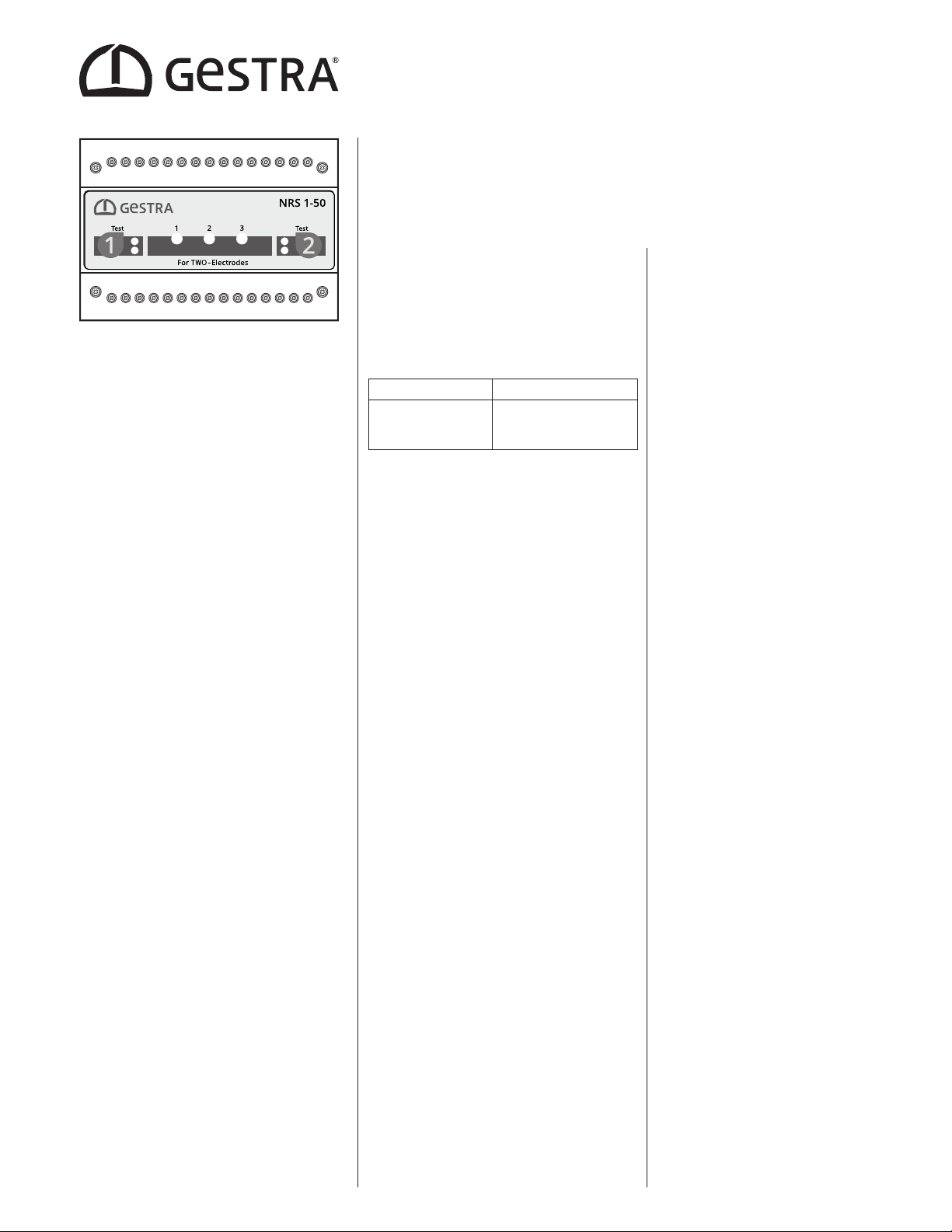
Water Level Limiter
Level Switch
NRS 1-50
For TWO electrodes
Data sheet 850711-00
Issue date: 09/21
USA
Technical data
Supply voltage
24 VDC +/–20%, 0.3 A; SELV / PELV / CLASS2
100 – 240 VAC +10/-15%, 47 – 63 Hz, 0.2 A (optional)
Fuse
External 0.5A; UL category JDYX, e.g., RND 170-00012
Power consumption
7 W
Response sensitivity [Water conductivity at 77°F (25°C)]:
> 5 ... < 5000 ppm (> 10 ... < 10000 µS/cm)
Connecting the level electrode
Please use the following to connect the level electrode(s):
nA shielded, multi-core TC-ER control cable with a minimum
wire size of AWG18, e.g., OELFLEX CONTROL TM CY 5G1.
Max. length 328ft (100m).
Safety circuit
2 volt-free NO contacts, 6 A 250 V AC / 30 V DC cos ϕ= 1.
Off delay 3 seconds. Inductive loads must have interference
suppression (RC combination) in accordance with the manu-
facturer's specification.
Signal output
2 volt-free outputs for external signaling without a de-
lay, 24 V DC, max. 100 mA (semiconductor output).
Connection of control cables 2 x AWG20 (0.5 mm2).
Indicators and controls
2 buttons for testing and diagnosis, 4 red/green LEDs for indi-
cating operating state and alarm. 3 red LEDs for fault diagnosis,
2 2-pole code switches for setting the number of electrodes.
Terminal box
Terminal box material: base of black polycarbonate, front of
gray polycarbonate. Terminal strips can be removed separately
Terminal box attachment: Mounting clip on support rail
TH 35, EN 60715.
Electrical safety
Pollution degree 2, overvoltage category II according
to UL 60730-1.
Protection
Terminal box: IP 40 according to EN 60529
Terminal strip: IP 20 according to EN 60529
As a UL open type, the equipment must be installed in a
control cabinet.
Weight
Approx. 1.1 lb (0.5 kg)
Ambient temperature
at power-on 32° ... 131°F (0° … 55°C),
in operation 14° … 131°F (-10° … 55°C)
Transport temperature
-4°F ... +176°F (-20°C ... +80°C) (<100hours),
defrosting time of de-energized equipment before it can be
put into operation: 24 hours.
Storage temperature
-4°F ... 158°F (-20°C ... +70°C),
defrosting time of de-energized equipment before it can be
put into operation: 24 hours.
Relative humidity
Max. 95%, non-condensing
Site altitude
Max. 6560 ft (2000 m)
850711-00/09-2021cm (809139-00) · GESTRA AG · Bremen
Water Level Limiter
Level Switch
NRS 1-50
Interlock
In the event of an alarm, the NRS 1-50 level switch interlock
does not take place automatically. If the installation requires
an interlock, this must be implemented in the external (safety)
circuit.
It is important that the interlock is not deactivated when the
level switch signals a malfunction to the diagnostic LEDs or
the signaling outputs.
In order to guarantee Class C function with a Level 2 fail-safe
rating in accordance with UL 60730-1, both signaling outputs
must be monitored during interlock deactivation. To conform
with ASME CSD-1 two low water level limiters are required.
Power supply
A safety power supply unit (SELV / PELV / CLASS2) must be used
to supply the NRS 1-50 level switch with 24V DC.
Directives and standards
The equipment has been tested and approved for use in the
scope governed by the following directives and standards:
Standards:
nUL 60730-1 and CAN/CSA E60730-1
General Requirements for Automatic Electrical Controls
nUL 60730-2-15 and CAN/CSA E60730-2-15
Requirements for Automatic Electrical Water Level
Sensing Controls
Improper use
There is a danger of death due to explosion if the equipment
is used in potentially explosive atmospheres.
Do not use the equipment in potentially explosive atmospheres.
How to order and specify
GESTRA level switch NRS 1-50 as a water level limiter
For
TWO electrodes
Supply voltage ..................
Sensitivity 5 ppm (10 µS/cm)
Dimensions
2716
12345678
17 18 19 20 21 22 23 24
9
25
10
26
11 12
28
13
29
14
30
15
Test Test
Wiring diagram
3.94 in (100 mm)
2.91 in (74 mm)
4.72 in (120 mm)
Key
8Supply voltage
9Signal output 1/2 for external alarm 24V DC, 100mA (semiconductor output)
0Safety circuit, input and output, external fuse T1A (slow blow)
aJumper, provided by customer
bLevel electrode NRG 1...-50
CGP Central grounding point in control cabinet
GESTRA AG
Münchener Straße 77, 28215 Bremen, Germany
Tel. +49 421 3503 0, Fax +49 421 3503 393
e-mail [email protected], website www.gestra.com
Please note our general terms of business.
2716
12345678
17 18 19 20 21 22 23 24
9
25
10
26
11 12
28
13
29
14
30
15
1
2
3
++-
L
M0,5A
(+) (-)
-
N
1
2
3
8
909
a
0
c c
CGP CGP
NRG 1..-50 NRG 1..-50

Other manuals for NRS 1-50

3

Other GESTRA Measuring Instrument manuals

GESTRA LRG 16-40 User manual

GESTRA

GESTRA LRG 16-40 User manual

GESTRA NRG 16-38 S User manual

GESTRA

GESTRA NRG 16-38 S User manual

GESTRA NRG 26-40 User manual

GESTRA

GESTRA NRG 26-40 User manual

GESTRA LRG 16-4 Installation instructions

GESTRA

GESTRA LRG 16-4 Installation instructions

GESTRA LRGT 16-1 Manual

GESTRA

GESTRA LRGT 16-1 Manual

GESTRA NRG 26-21 Manual

GESTRA

GESTRA NRG 26-21 Manual

GESTRA NRG 10-52 User manual

GESTRA

GESTRA NRG 10-52 User manual

GESTRA NRG 16-51 User manual

GESTRA

GESTRA NRG 16-51 User manual

GESTRA VK 14 User manual

GESTRA

GESTRA VK 14 User manual

GESTRA NRT 2-1 Quick guide

GESTRA

GESTRA NRT 2-1 Quick guide

GESTRA NRG 211-1 User manual

GESTRA

GESTRA NRG 211-1 User manual

GESTRA SRL 6-60 User manual

GESTRA

GESTRA SRL 6-60 User manual

Popular Measuring Instrument manuals by other brands

Kewtech KTD30 user manual

Kewtech

Kewtech KTD30 user manual

YOKOGAWA EXA TB TB400G user manual

YOKOGAWA

YOKOGAWA EXA TB TB400G user manual

Princeton Instruments LS 785 user manual

Princeton Instruments

Princeton Instruments LS 785 user manual

YOKOGAWA TDLS200 Addendum Instruction Manual

YOKOGAWA

YOKOGAWA TDLS200 Addendum Instruction Manual

LIVIN Med FO0920A user manual

LIVIN Med

LIVIN Med FO0920A user manual

Minolta COLOR METER IIIF - PART 1 manual

Minolta

Minolta COLOR METER IIIF - PART 1 manual

DOLD IP 5883 Installation / monitoring technique

DOLD

DOLD IP 5883 Installation / monitoring technique

Motrona touchMATRIX PN350 operating manual

Motrona

Motrona touchMATRIX PN350 operating manual

Horiba Scientific LAQUA 200 Series quick guide

Horiba Scientific

Horiba Scientific LAQUA 200 Series quick guide

DataCan 109684 user manual

DataCan

DataCan 109684 user manual

Tokyo Keiki HC-10 Installation & operation manual

Tokyo Keiki

Tokyo Keiki HC-10 Installation & operation manual

Mitutoyo ID-U user manual

Mitutoyo

Mitutoyo ID-U user manual

Imed PITCH ANGLE user manual

Imed

Imed PITCH ANGLE user manual

Prostat CVM-780 user manual

Prostat

Prostat CVM-780 user manual

FRO­NIUS Smart Meter IP quick start guide

FRO­NIUS

FRO­NIUS Smart Meter IP quick start guide

Check-line DCF-900 user guide

Check-line

Check-line DCF-900 user guide

ProAir FGP Series manual

ProAir

ProAir FGP Series manual

E-line CJ-HDR104 user manual

E-line

E-line CJ-HDR104 user manual

manuals.online logo
manuals.online logoBrands
  • About & Mission
  • Contact us
  • Privacy Policy
  • Terms and Conditions

Copyright 2025 Manuals.Online. All Rights Reserved.