Reval OPALE SENSE User manual

EN Instruction manual
SHOWER PANEL with secured disinfection system
OPALE SENSE
3011.01

SUMMARY
CONTENTS PAGES
GENERAL DRAWINGS 2
- - - - - - - - - - - - - - - - - - - - - - - - - - - - - - - - - - - - - - - - - - - - - - - - - - - - - - - - - - - - - - - - - - - - -
DIMENSIONS 2
- - - - - - - - - - - - - - - - - - - - - - - - - - - - - - - - - - - - - - - - - - - - - - - - - - - - - - - - - - - - - - - - - - - - -
TECHNICAL SPECIFICATIONS 3
- - - - - - - - - - - - - - - - - - - - - - - - - - - - - - - - - - - - - - - - - - - - - - - - - - - - - - - - - - - - - - - - - - - - -
RANGE OF APPLICATION 3
- - - - - - - - - - - - - - - - - - - - - - - - - - - - - - - - - - - - - - - - - - - - - - - - - - - - - - - - - - - - - - - - - - - - -
DIRECTIONS FOR USE
SENSITIVE MIXER – OPERATION 4
WASHINGOFPATIENT 4
ANTI-BURN SAFETY DEVICE 5
DISINFECTION 5
- - - - - - - - - - - - - - - - - - - - - - - - - - - - - - - - - - - - - - - - - - - - - - - - - - - - - - - - - - - - - - - - - - - - -
MAINTENANCE
ADDITIONOFDISINFECTANT 6
CLEANING OF THE CONTROL PANEL 6
- - - - - - - - - - - - - - - - - - - - - - - - - - - - - - - - - - - - - - - - - - - - - - - - - - - - - - - - - - - - - - - - - - - - -
MAINTENANCE FORM (LOGBOOK) 7
- - - - - - - - - - - - - - - - - - - - - - - - - - - - - - - - - - - - - - - - - - - - - - - - - - - - - - - - - - - - - - - - - - - - -
« RADA SENSE » USER’S MANUAL 8 & +
- - - - - - - - - - - - - - - - - - - - - - - - - - - - - - - - - - - - - - - - - - - - - - - - - - - - - - - - - - - - - - - - - - - -
1/7

GENARAL DRAWINGS
DIMENSIONS
2/7
Digital thermostatic mixer
Door to access to the tank
Cleaning shower flow regulation
Digital temperature display
Disinfection sop valve
Cleaning shower
Disinfection shower
Valve lock with key
18
45cm
60cm
16

TECHNICAL SPECIFICATIONS
MODELS:
REF. 3011.01 Shower panel "OPALE SENSE" with sensitive thermostatic mixer
DATAS:
•Steel frame anti-corrosion coated.
•Cover in white polyester.
•Chromed shower up-stand with soap support.
•Rada sense shower concealed digital mixing valve offering programmable max, min & default temperatures,
automatic temperature on outlet selection, duty flush and thermal disinfection with datalogging capabilities.
•Non-return valves and anti-burn safety device.
•Disinfection shower handset with trigger.
•Cleaning shower handset.
•Flow intensity adjustment valve.
•Disinfection valve secured by key.
•Door to access to the tank of disinfectant secured by lock with key.
•Suction device of the disinfectant product with stop valve and 1 liter tank.
•Digital temperature display.
CONFORMITY:
•73/23/CEE.
•89/336/CEE.
•NF EN 60335-1.
•NF C 15-100.
RANGE OF APPLICATION
The 3011.01 Opale Sense control panel has been studied to wash patients on shower trolley and to make the disinfection of
mattress, pillow, wall of bathtub...
The shower panel must be used only by qualified people who have read and understood the user manual.
The shower panel is intended to be used only for wash patient.
Never use the disinfection shower on the patients.
! The manufacturer will not be responsible if the product is used, changed or assembled in other way than prescribed in
this manual.
3/7

DIRECTIONS FOR USE
CONCEALED DIGITAL MIXING VALVE RADA SENSE:
To adjust the water temperature,, pass your finger in front of the cold water sensitive captor (blue triangle) or in front of the
hot water (red triangle) according to the temperature desired.
Max outlet temperature for shower: 40°C
Default at start-up : 37°C.
Check water temperature before each use.
CLEANING SHOWER :
To use the cleaning shower, pass your finger in front of the pictogram
It is possible to adjust the flow intensity with the tap.
After each use, turn off the valve.
4/7

DIRECTIONS FOR USE
ANTI-BURN SAFETY :
If breaking of cold water feeding occurs, risks of burn are avoided.
DISINFECTION :
- Unlock the disinfection valve thanks to the key.
- Déverrouiller la vanne de désinfection à l’aide de la clé. For that purpose, turn the key counterclockwise.
- Take the disinfection shower
- Carefully sprinkle parts to disinfect.
Do not use the disinfection shower on the patient.
Wait in order to respect the action time prescribed in accordance with the disinfectant used. Action time: 2
minutes for B.F.R. 3.4. product.
Carefully rinse them with the cleaning shower, in order to eliminate any trace of bactericide.
5/7

MAINTENANCE
ADDITION OF DISINFECTANT :
The control panel is equipped with an automatic system to determine the quantity of disinfectant.
The disinfection system includes :
•1 lites tank receiving the disinfectant product.
•1X plunger with calibrated tube, located in the tank, and connected by a flexible going through the top of
the venturi (white plastic part).
•1 disinfection shower.
Dilution :
The mixing of water and disinfectant inside the disinfection shower is made in 2 stages :
First :
Manual dilution inside the tank.
Second :
The suction device (venturi) ensures a dosage of 10% of the aspirated product from the tank.
Exemple :
The disinfectant BFR 4.0 must be used with a final dilution of 0,4%.
1) Manual dilution inside the tank at 4%, that is 40ml of BFR 4.0 for 960ml of water.
2) Complementary dilution of 10% ensured with cold water by the suction device (venturi).
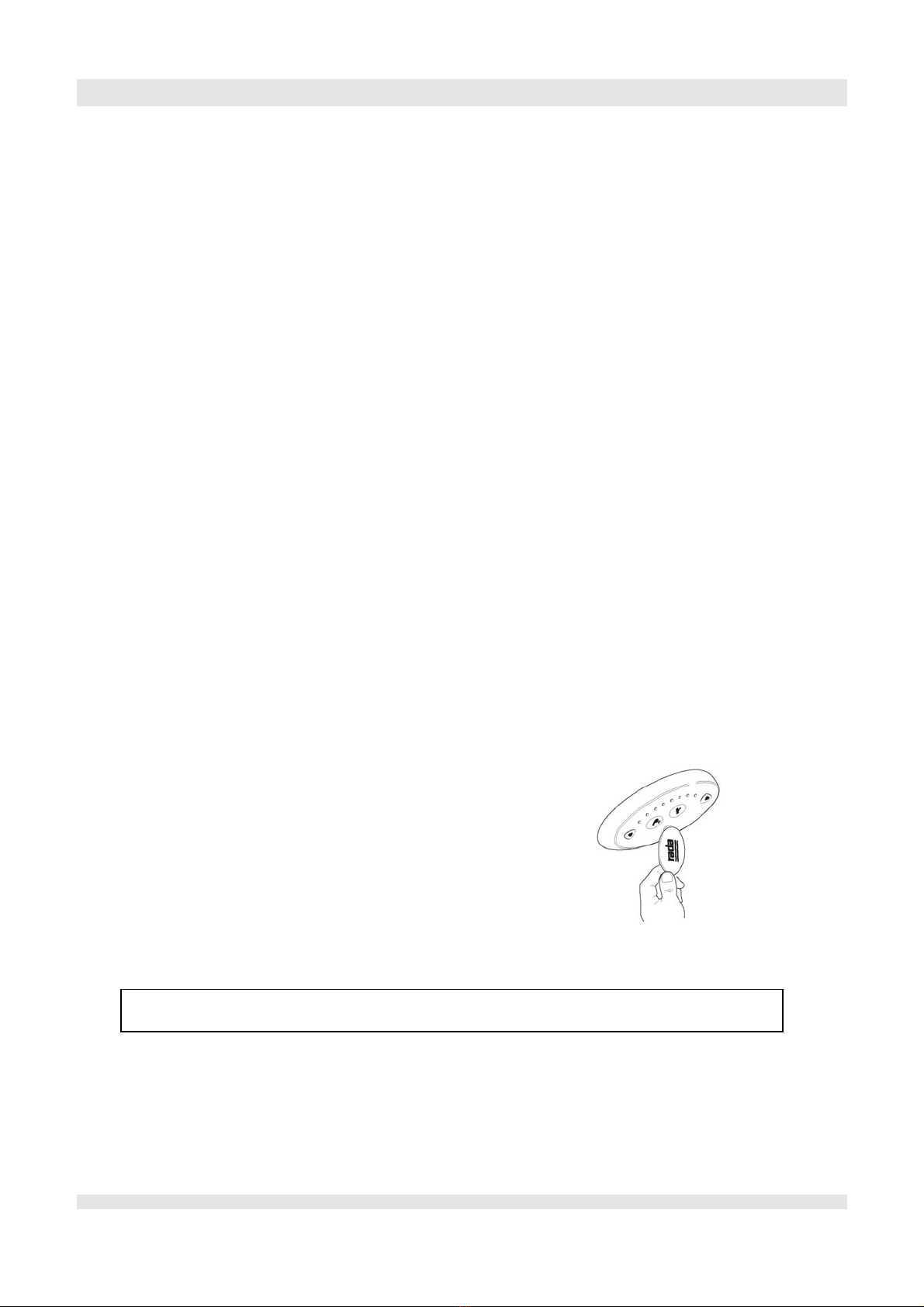
CLEANING OF THE CONTROL PANEL :
To clean the “rada sense” control panel, take the magnetic key and pass it in front of the infra red of the control
panel to desactivate it. (during 30 minutes) To reactivate the control panel, do the inverse operation.
Only use liquid products (liquid soap).
Don't use abrasive products like "scouring cream" to avoid scratches on the tub surface "Gelcoat".
Furthermore, to eliminate calcareous marks settled by water moving, we recommend to use the scaler (Gel Servex ).
Do not use liquid soap and the scaler (Gel Servex) on the control panel elements;
Rada sense mixer and whirlpool control.
6/7

MAINTENANCE FORM (LOGBOOK)
Agent
(name and
signature)
Corrections
Observations
Cleaning of the
showers
Cleaning of filter cartridge
of mixer
Control
date
7/7

FRANCE :
Reval®
Z.A. Fief des Prises
Usseau 17220 Sainte Soulle
Tel: (33) 05.46.42.04.16
Fax: (33) 05.46.43.06.38
www.groupe-reval.com
UNITED KINGDOM :
Reval® Continuing Care Limited
Unit 17 Brynmenyn Busines Centre
St Theodore's Way - Brynmenyn
CF32 9TZ BRIDGEND - WALES
Tel: 01656 721 001
Fax: 01656 720 006
www.reval-group.com

1
IMPORTANT
Installer: This Manual is the property of the customer
and must be retained with the product for
maintenance and operational purposes.
PRODUCT MANUAL
Rada Sense Shower T3 DMV

2
CONTENTS
DESCRIPTION..........................................................................................3
SAFETY : WARNINGS .............................................................................3
PACK CONTENTS.................................................................................... 4
SPECIFICATION.......................................................................................5
Standards and Approvals ..................................................................... 5
Additional Information for Type 2 and 3 Installations............................ 6
Supply Conditions ................................................................................ 6
INSTALLATION.........................................................................................6
POWER SUPPLY UNIT (PSU).................................................................. 8
RADA SENSE CONTROL PANEL ...........................................................9
RADA SENSE (DMV)..............................................................................10
COMMISSIONING .................................................................................. 11
Maximum Temperature Setting .......................................................... 12
OPERATION ...........................................................................................13
Duty Flush .......................................................................................... 13
Disinfection.........................................................................................13
CLEANING..............................................................................................14
FAULT DIAGNOSIS ................................................................................15
Self-diagnostic Errors.........................................................................17
PLANNED MAINTENANCE ................................................................... 18
Healthcare..........................................................................................18
Frequency of In-service Tests ...........................................................19
Checkvalves and Filters .....................................................................21
SPARE PARTS .......................................................................................23
ACCESSORIES ......................................................................................23
CUSTOMER CARE.................................................................................24

3
A range of concealed 1/2” digital mixing valves (DMV) with wall mounted no-touch
control panel for ow and temperature control. Functions include timed ow control,
duty ush and thermal disinfection.
SAFETY : WARNINGS
The function of this DMV is to deliver water consistently at a desired temperature.
This requires that:
1. It is installed, commissioned, operated and maintained in accordance with the
recommendations given in this Manual.
2. Periodic attention is given, as necessary, to maintain the product in good
functional order. Recommended guidelines are given in the PLANNED
MAINTENANCE section.
3. Using this product outside the specication limits given in this Manual can
present potential risk to users.
4. The electrical installation must comply to “BS 7671 - Requirements for Electrical
Installations”, commonly referred to as the IEE Wiring Regulations - Part 7, or
any particular regulations and practices, specied by the local electricity supply
company.
5. DO NOT t any form of outlet ow control i.e. trigger handset. Use only
recommended ttings.
The use of the word ‘failsafe’ to describe the function of any mixing valve is both
incorrect and misleading. This electronic valve incorporates additional shut-off
devices to improve the level of safety however, in keeping with every other mechanism
it cannot be considered as being functionally infallible.
Where chlorine disinfection is practised, DO NOT exceed a chlorine concentration of
50 mg/l (ppm) in water, per one hour dwell time. Such procedures must be conducted
strictly in accordance with the information supplied with the disinfectant and with all
relevant Guidelines/Approved Codes of Practice.
DESCRIPTION

4
PACK CONTENTS
1 x Shower Control Panel
Magnetic Key
1 x Digital Mixing Valve (DMV)
4 x Fixing Screws
4 x Wall Plugs
1 x Power Supply Unit (PSU)
2 x Fixing Screws
2 x Wall Plugs
2 x Installation Templates
(DMV Installation Template, on the Packaging)
6 x Rubber Feet
UK Rada Sense T3 Programmer CD
Suppression Ferrite

5
Standards and Approvals
This Rada Sense digital mixing valve (DMV) complies with all relevant directives
for CE marking.
The Rada Sense DMV is a type 1 electronic, independently mounted control for
surface mounting.
General
Pollution Degree 3
Rated Impulse Voltage Mains Supply - 2.5 kV
12 V DC supply to valve - 500 V
Suitability for Drinking Not suitable
Connections Flat face union connections
Pressures
Maximum Static Pressure 1000 kPa (10 bar)
Minimum Pressure Loss Refer to Note 20 kPa (0.2 bar)
Supply Pressure Differential 30 kPa (0.3 bar) with recommended Rada outlet ttings
Minimum Flow Rate 6 L/min (<500 kPa maintained pressure)
8 L/min (>500 kPa maintained pressure)
Temperatures
Factory Pre-set (Blend) Shower Max. 41 °C, Min. 30 °C, Default at start-up 38 °C
Factory Pre-set Duty Flush 30 °C
Programmable Range Max. 33 - 50 °C
Min. 30 - 47 °C (full cold can also be selected)
Default at start-up 30 - 50 °C
Minimum Blend Temperature
Differential from Hot Supply
2 °C
Optimum Thermostatic
Control Range
30 - 50 °C
Cold Water Range 1 - 20 °C
Hot Water Range 50 - 65 °C (85 °C for disinfection)
Temperature Stability ± 1 °C at recommended supply conditions
Ambient Temperature Greater than 1 °C, max. 40 °C
Maximum Relative Humidity 95% non-condensing
Electrical
Supply Voltage 100 - 240 V RMS 50 - 60 Hz
Maximum Load 20 W at 12 V DC
Control Panel Cable Length 3 m supplied (6 m max.)
Times Factory Settings Programmable Range
Flow Time to Auto Shut-off 30 seconds 5 seconds to 60 minutes
Duty Flush Cycle 2 minutes 1 - 59 minutes
Duty Flush Waiting Time 12 hours 1 - 983 hours
Disinfection
Minimum Temperature 60 °C 60 - 85 °C
Minimum Time 5 minutes 0 - 50 minutes
Reduced Flow rate No Yes or No
Note! The pressure loss of a system (valve and outlet tting) is the average of the two inlet pressures minus the back
pressure, where the back pressure is determined by the ow resistance of any outlet tting.
SPECIFICATION

6
INSTALLATION
Additional Information for Type 2 and 3 Installations
To achieve the safe water temperatures expected of approved valves, it is essential
that the valves are used only for the applications covered by their approved
designations, with the appropriate water supply pressures and temperatures, and it
is commissioned and maintained in accordance with the recommendations contained
in this guide.
Model Designation Code Type 2 Designation Code Type 3
Rada Sense Shower HP S - LP S HP S - LP S
The permitted application details are:
Designation Operating Pressure
Range
Application Mixed Water
Temperature °C *
HP S High Pressure Shower 41 °C maximum
LP S Low Pressure Shower 41 °C maximum
* Mixed water at the discharge point.
Supply Conditions
Valves operating outside these specications can not be guaranteed to operate as
Type 2 or Type 3 valves:
Operating Pressure Range High Pressure Low Pressure
Maximum Static Pressure - kPa (Bar) 1000 (10) 1000 (10)
Maintained pressure, hot & cold - kPa (Bar) 100 - 500 (1 - 5) 20 - 100 (0.2 - 1)
Hot supply temperature - °C 52 - 65 52 - 65
Cold supply temperature - °C 5 - 20 5 - 20
General
Installation must be carried out in accordance with these instructions, and
must be conducted by designated, qualied and competent personnel.
The installation must comply with the “Water Supply Regulations 1999
(Water Fittings)”.
Caution! The DMV and PSU must be installed in a dry area and where it will not
freeze.
Note! The DMV must be installed in an area where it is accessable to do any
maintenance tasks e.g. removal of the cover, cleaning the strainers etc.
Flat face union connections must be used on the inlet and outlet connections of the
DMV for ease of maintenance.

7
3 amp switched
fused spur box
Control panel
PSU
DMV
Outlet
Hot inlet
Cold inlet
Showerhead
To mains power supply
Metal pipework
must be
earth bonded
Suppression Ferrite,
refer to Note.
Note! The Data Cable must be placed through the Suppression Ferrite and then looped around the
cover. The Suppression Ferrite must be tted as close to the Control Panel as possible.
Installation Schematic
1. Inlet and outlet isolating valves must be installed close to the DMV for ease of
maintenance.
2. The use of supply-line or zone strainers will reduce the need to remove debris at
each mixing valve point. The recommended maximum mesh aperture dimension
for such strainers is 0.5 mm.
3. Inlet pressure tappings which allow measurement of the inlet pressures to
the mixing valve under operating conditions are particularly recommended for
healthcare applications.
4. Pipework must be rigidly supported and avoid any strain on the connections.
5. Pipework dead-legs should be kept to a minimum.
6. Supply pipework layout should be arranged to minimise the effect of other outlet
usage upon the dynamic pressures at the mixing valve inlets.
7. Inlet and outlet threaded joint connections should be made with PTFE tape or
liquid sealant. Do not use oil-based, non-setting joint compounds.
8. To eliminate pipe debris it is essential that supply pipes are thoroughly ushed
through before connection to the spout and to the Rada Sense DMV.
9. The DMV may only be orientated in the positions shown when mounted on a rigid
vertical surface and on top of a rigid horizontal surface in any orientation.

8
Outlet
Hot inlet
Cold inlet
Outlet
Hot inlet
Cold inlet
Outlet
Hot inlet
Cold inlet
Mounting on a
Vertical Surface
Mounting on a
Horizontal Surface
Note! If the DMV is installed in a different orientation to those shown above, it may
cause the DMV to malfunction e.g. cause airlocks, water ingress and could effect
the thermal performance of the DMV.
The DMV MUST NOT be installed in the orientations shown below.
Outlet
Hot inlet Cold inlet
Outlet
Hot inlet
Cold inlet
10. For the installation of your spout, refer to the Sense Spout Kits Installation
Manual.
POWER SUPPLY UNIT (PSU)
Warning! Isolate mains power supply before starting installation. The PSU must be
connected to a 3 amp switched fused spur box.
1.5 m cable
3.0 m cable
Fixing screws (2 off)
0.5 m cable

9
RADA SENSE CONTROL PANEL
Template
Caution!
Do not trap the cable.
Remove excess sealant.
7
Caution!
Make sure Silicone Sealant is applied in the groove on
the back of the Control Panel to stop water ingress into
the data cable access hole in the nished wall.
5 6
3 4
1
2
The Rada Sense Control Panel MUST NOT be installed in areas where high
frequency lighting is used. Certain types of compact uorescent and low voltage
lighting use high frequency lamps that can interfere with the infrared system used
in the control panel. We recommend standard switch-start uorescent lighting to be
installed within these areas.
Note! If the data cable is installed within a stud partition or recessed into a wall, make
sure it is placed within a suitable conduit to allow easy removal during servicing.
The Control Panel must only be installed onto a at wall surface.

10
RADA SENSE (DMV)
Short Cable
Connection
for the
Control Panel
PSU Cable
Connection
Moulded Grommet
Template
Note! After installing the PSU and
Control Panel cables, if necessary,
carefully push the wires between the
grommet and connector to one side.
1 2
3
4
5
Cable from
the DMV
Cable from the
Control Panel
7
Outlet
Hot Inlet
Cold Inlet
8
6
9

11
COMMISSIONING
Commissioning must be carried out in accordance with these instructions, and
must be conducted by designated, qualied and competent personnel.
Note! For Healthcare Installations, all results must be recorded.
1. Restore the water supply and check that there are no leaks.
2. Restore the power supply.
3. Position your hand over the ow sensor (indicated by a tap) on the control panel
to start the DMV, to ush out any air.
4. Check the supply temperatures and pressures are within the range stated
in SPECIFICATIONS and the guidance information on the prevention of
legionella.
5. For Type 2 and 3 installations, check that the designation of the DMV matches
the application. The supply pressures and temperatures are within the permitted
range for the application.
6. Check inlet pipework temperatures for correct function of checkvalves
i.e. the hot water does not cross ow into the cold water supply.
7. Check that the temperature(s) and ow rates obtainable are acceptable.
8. Carry out a performance check:
Healthcare
Isolate the cold water supply to the mixing valve and monitor the mixed water
temperature. Record the maximum temperature achieved and the nal stabilised
temperature on restoration of the cold water supply.
Note! The nal stabilised mixed water temperature should not exceed 43 °C.
Any higher temperatures should only occur briey.
Commercial
Locate another outlet on the common cold water supply close to the mixing
valve (operating this outlet should cause a drop in supply pressure), and
note the subsequent effect on blend temperature (should be no more than
2 oC change).
Table of contents
Other Reval Bathroom Fixture manuals
Popular Bathroom Fixture manuals by other brands

Helvex
Helvex Kubica E-3005 General Instruction

Kesseböhmer
Kesseböhmer Turn-Motion Mounting instructions

Bristan
Bristan FH SLSQ01 C Fitting instructions

OPHARDT HYGIENE
OPHARDT HYGIENE SanTRAL Plus SMART OBU 25 instruction manual

BELLOSTA
BELLOSTA M-Uno 8811/1A Installation instruction

Axor
Axor Citterio Select 230 2jet 39867 9 Series Instructions for use/assembly instructions