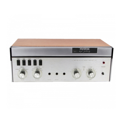
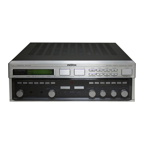
Revox A78 User manual

ReVox n;7ei VERSTARKER
AMPLIFIER
AMPLIFICATEUR
SERVICE-ANLEITUNG SERVICE SHEET I NSTRUCTIONS DE SERVICE
FUN KTIONSBESCHREIBUNG
'1. Eingangsstufe 1.078.'110
D e Eingangsstufe enthält Vorverstärker
und Entzerrer. Die Empflndlichkeit der
elnzelnen Eingange wird je nach Stellung
oe. I ingd.gswdl scha tpr. durcl- err" v"rt
atrle Gegenkopplung best mmt. O101 ist
ein rauscharmer pnp Transistor, dessen
Emitter im Gegenkopplungszwe g der gle ch
stromgekoppe tef Stufe liegt. ln der Kas'
kadenscheltung von O102 u.d Ol03 wirl<t
O103 a s Ko ektorwiderstand mit qrosser
Tpedon/ f-r NF.Sig^ai" Lnd gp-i.gpr
Gle chstromwiderstand. Durch die Gleich
stromgegenkopp ung über R106 w rd ein
stabr er Arbeitspunkt gewährleistet. Die
PHONO Entzerrung (RIAA-lEC) erfolgt
durch die RC-Glieder R 1 14 C109, R 1 'l 5
urd Cl10 im NF.Gpqpllupt,iung.zw"g
und R106 im Gle chstromzweig. ln Ste lung
TAPE, TUNER und AUX ist die Gegen
l<opplung frequenzunabhängig (R1 1B). ln
Stel ung tvllCRO ist die Gegenkopplung
ausgeschaltet. Die eifzelnen Tonspannungs
qro .- wc d"n nrt. \ Vo ,' g,arr 6 ngp
pegelt: in St.rllung PHONO wird die Gegen
ropp u.q v" ,."r1 D " \llCRO E .gänge
s nd nicht regelbar und sind an den Buch-
sen paralle geschaltet. Bei Verwendung
von Stereo lVikrophonen oder einem Nlikro-
phon pro Kanal ist die Verbindung zu
losen. Der Ausgang des Entzerr Vorver
starkers fuhrt auf den Betriebsartenschal.
ter: N,4ONO,/STEREO/CH l/CH ll.
2. Filterstufe 1.178.169
Die als aktives Filter geschaltete Stufe mit
denTransistoren 0240 und O241 hat folgen-
de Eigenschaftenr Tiefendämpfung durch
C241, C242, R240; Höhendämpfung durch
R243, R244, C243 und Präsenzwirkung bei
2.5 kHz durch C246, C248 und R251. Das
LOUDNESS LOWFilter bewirkt eine Ab'
senkung des NFPegels bei gleichzeitiger
physioloqischer Frequenzgangkorrektur. Die
TAPE l\,1ON ITOR-Taste schaltet den Vorver-
stärker ab und verbindet den Eingang TAPE
N4ONITOR übe. Loudness Filter und Klang-
regler mit den Endstufen ( Hinterbandkon
trolle ). Der Ausgang der Filterstufe führt
auf den Lautstärkeregler und die Ausgänge
TAPE OUTPUT.
3. Klangreglerstufe 1.078.106 - 1.078.215
D,e StulPn O30l trno O302 "'oe t'r r^
IVl,llptsrp' J1q o"s Bdl"1( prPglPrc rll pi'P'
Verstärkunq von 20 dB. Die Balanceregelung
erfolgt im Gegenkopplungszwe g dieser Stu
fen. lm Gegenkopplungszweig der Stufe
O3O3-0304 befindet sich das Netzwerk
fur die Anhebung, bzw. Absenl<ung der Hö
hen und Tiefen.
4. Treiber- und Endstufe 1.174.114
Die NF-Signale gelangen an die Basis des
Transistors O501, der in normaler Emitter-
schaltung arbeitet. Das verstärkte Signal
wird am Kollektorwiderstand R504 abge-
nommen und direkt an die Basis des
Transistors O502 geführt, welcher eben-
falls in Emitterschaltunq arbeitet. Die
Stromgegenkopplung am Widerstand R508
wird für NF durch Kondensator C502 auf-
gehoben. Da der Kollektorwiderstand R509
infolge der Bootstrap-Wirkung von C503,
sowie der hohen Eingangsimpedanz der
Transistoren 0503 und 0504 sehr gross;st,
erreicht diese Stufe eine Spannungsver-
stärkung von gegen 60 dB. Durch die nicht'
lineare Charakteristik der Dioden D501 und
D502 wird eine stabile Basis Emitterspan'
nung der Treibertransistoren und damit eine
von der Betriebsspannung weitgehend unab-
hängige Arbeitspunkteinstellung erreicht.
Die thermi$he Kurzzeitstabilität wird durch
R514 und R515 erzielt; die Langzeitstabili'
tätwird durch die thermische Kopplung der
Dioden D501 und D502 mit dem Kühlkör-
per der Leistungstransistoren erreicht. Bei
grossen Aussteuerungen werden die Dioden
D504 und D505 leitend, womit zu jedem
1 t -widerstand ein o.47o,widerstand
parallel geschaltet wird. DieSpannungsfestig-
keit der Leistungstransistoren O505 und
0506 wird durch die Widerstand-Diode-
Kombination im Emitterkreis künstlich er-
höht ( 0505: R514-R528-D504, 0506:
R516 D506 ).
Spule L501 und Boucherot'Glied R518-
C506 sichern ein stabiles Verhalten der
Endstule, auch bei ertremer kapazitiver
Lastbiszu 1 pF, sowie ein optimales Recht-
eckverhalten bei höchsten Frequenzen und
voller Leistung.
Zwei Lautsprecherbuchsen pro Kanal wer
den mit den Tasten SPEAKERS OFF unab-
hängig voneinander geshaltet; damit ist der
Anschluss von 2 Lautsprechergruppen mög-
lich (minimale resultierende lmpedanz: 4 f,l
pro Kanal ).
5. Neuteil 1.17e.235
Die Speisung der Endstufen erfolgt sym-
metrisch (+41 V und 41 V ), mit kapazi-
tiv erzeugtem Mittelpunkt. Diese elektrische
lvlitte ist lediglich über die Abschirmung
der NF-Zuführung mit der l\4asse der Vor-
stuf en-Stromversorgu ng verbunden.
Die entsprechende + 41V -Spannung wird
durch den thermostatischen Schalter S901
{ bzw. 5902 ) abgeschaltet, wenn die
Temperatur des Endtransistoren-Kühlkör
pers 80o C übersteigt.
Ein kurzrchlusssicheres, stabilisiertes Netz
teil qewährleistet eine brumm- und rausch-
freie Spannung von 24 V. Die Verbindung
lvldsse zu Gerätechassis erlolgt nur an einem
Punkt: der Lötfahne zwischen den beiden
Kopfhörerbuchsen.
EINSTELLUNGEN
Die Peqelvorregler l9 bis 23 dienen zur Ein-
pegelung der verschiedenen Tonspannungs
quellen. Diese Regler werden normalerweise
vom Besitzer des Gerates ei.gestellt. Die
restlichen Einstellungen beziehen sich auf
die Endstufen.
1. Gleichspannung am Lautsprecherausgang:
Verstärker ohne Last, n cht angesteuert.
DC'Voltmeter am Lautsprecherausgang
anschliessen und mit Trimmpotentio
meter R51 I auf 0 V t 50 mV abgleichen
2. Ruhestrom der Leistungstransistoren
- Zweites DC Voltmeter parallel zu R514
an den lvlesspunkten auf Lötseite (+ bei
Steckerleiste, am oberen Rand) an
schl iessen.
- N4it Trimmpotentiometer R520 eir'en
Spannungsabfall von 20 mV einstellen
(= 20 mA an 1 J)).
Diese Einstellungen zeiqen eine leichte
Abhängigkeit voneinander und sollen des
halb wechselweise im Kaltzustand des
Gerätes vorgenommen werden. Eine nach
trägliche Abweichung von diesen Werten
bei erwärmtem Geiät ist belanglos und
soll nicht korrigiert werden.
FEHLERSUCHE
'1. Verstärker ganz ausgelallen
ln den meisten Fa len ist der Ausfall des
Verstärkers aui einen Defekt der Endstufen
zu rückzufuhren.
Eventuell durchqebrannte Netzsicherung er'
setzen und Verstärker r.lber Regeltrenntrafo
und Wattmeter an das Netz anschllessen.
Rege trafo langsam hochdrehen, bei gleich'
zeitiger Beobachtung der Leistunqsaufnah-
me am Wattmeter; grössere Abweichungen
des nomlna en Leerlaufwertes ('12 W) nach
oben oder nach unten lassen auf defekte
Endstufen schliessen. l\lessung der Span
nungen und Strome der verdächtigten Stu
fen vornehmen.
Spannungen an den Elkos C9o6 und C907,
bzw. C926 und C927 verglelchen: wird
eln Unterschied von mehr ais 1 0 9': ge-
messen (2.8. 30V an C906 und 50V an
C907), Gerätausschalten und beide Treiber-
prints 1.078.1 14 herausnehmen. Mit dem
Ohmmeter (auf Polar tät achtenl) die Sperr.
schichten der npn-Endtransistoren kontrol-
lieren: das lnstrument zeigt einen Ausschlag
bei positiver Basis qegenüber Emitter oder
Kollektor. Bei negativer Basis gegenuber
fmiUp' ode <orlekro , sowie .egdl ver
oder positlvem Kollektor gegenüber Emitter
zeigt das lnstrument keinen Ausschlag.
Der Ausfal eines Treibertrans stors hat
ne,sle ne_ Durcrbrucr der fndt'arsisto'er
1u Lo 9e und urE.Lehrr 'l '.iop'lrdns,cro
ren kontrollleref ufd Kontaktgabe der
Trimmpotentiometer-SchleiJer überprüfen.
2. Verstärker arbeitet schleht
Uberstcigt der Kiirrfaklor bei 'l kHz den
maximal zugelassenen Wert von 0.I 9'i b-"i
40W, so ist Translstor 0502 defekt. Tr tt
ein Tlefenabfali von mehrals 1 dB bel 20 Hz
auf, so ist C50l zu ersetzen.
st bel hohen Frequenzen der Kllrrfaktor
zu hoch oder der Frequenzgang schlecht,
oder zeigt eine l0 kHz Rechteckspannung
oe: pi1 orr.chp Ldc .tn Ubpt <hw ngcn.
so sind die Kondensatoren C504. C505 und
C506 zu Liberpruien.
Nach leder Reparatur muss der Spannungs
abfa I an den drei 1 J2 Widerständen bei einer
Leistung von 40W gemessen werden. Es
zeigt sich dabei, ob die drei dazugehörenden
Dioden noch funktionsfahig sind.
Nomina werte : An R514 ( (Testpunkte ) !nd
R51 5: 600-700 mV, an R5 l 6: 450-500 mV.
Dle Überschreitung dieser Werte lasst er
kenr,en, dass dle entsprechende Diode un-
terbrochen ist. Der Durchbruch einer Diode
zeigt sich durch eine Unterschre tung der
Nominalwerte an R514 und R515, bzw.
durch einen sehr k einen Spannungsabfa I
an R516.
CIRCUIT DESCRIPTION
1. lnput stage'1.078,1 10
The input stage cofsists of preamplificatlon
combined w th equalization networks. The
sensitivity of the various inputs is deter.
mined by varying amounts of negative
feedback which depends on the position of
rhe inpLt serpLtor. O101 is o low no .e p.n.
transistor whose emitter is in the feedback
circuitof the direct coupled amplifler stage.
The transistor O103 in the cascade con
nection oJ O102 and O103 acts as the
col ector resistor with a high impedance for
audio signals, whlle representing a low DC
.eri.rdnc.. A st"b F opprdrilg ooi"t ,s pn
su edby DC fe"db"cl vi" t1a Rl06,es.Lo .
Phono equdlization (BIAA IEC) is given by
th-" RCnetwork R114C109, R115 and
C1 10 in the audio feedback circuit, as well
as by R106 ln the DC path. With the selec'
tor in positions TAPE, TUNER and AUX
'eedback occ-rs ra R118 dro \ nol
' aque1, / selcclva. W,lh h. seloL o' tn
position lvllCRO, f eedback is completely
drsdbl"d. Leve rdrc_, g oI r1e vJ.rou\
sound sources is achieved by means of
preset nput controls; only in positlon
PHONO is thls done by varying the amount
of feedback. The micro inputs are con'
nected rn para le at therr rnput sockets and
there is no provision for level preadjustment.
When us ng stereo microphones, or one
microphone per channe, the parallel con
nection at the microphone input is to be
removed. The output of the equalizer
preamplifier connects to the mode selector
switch N.4ONO/STEREO/CH l/CH ll.
2. Filter stage 1.178.169
The active filter stage with transistors 0240
and 4241 provides low frequency attenua-
tion 6y C24'|-C242-R240, high frequency
attenuation by R243-R244-C243, and a
3.6d8 boost at 2.5 kHz (presence filter) by
C246-C248-R251. The LOUDNESS LOW-
Filter effects a basic reduction of the audio
level, while simultaneously introducing
physiological frequency response correction-
The TAPE N4ONITOR-button disconnects
the preamplifier and provides a direct signal
path f rom the input TAPE IVION ITOR via
the loudness filter and tone controls to the
output stages for off tape monitoring. The
output of the filter stage connects to the
volume control and to the sockets TAPE
OUTPUT as well.
3. Tonecontrol stage 1.078.106 1.O7A.215
Wlth the balance contro in center po
sition, the two transistors O301 and 0302
will provide 20 dB of gain. Ba ance
control is achieved in the feedback path of
those two stages. The networl< for bass and
treble control is located in the feedback
circuit of the amplifying stages formed by
0303 and 0304.
4. Driver and power output stages 1-17a,114
The audio signal is fed to the base of
transistor O501 which operates in a con-
ventional common emitter circuit. The
amplified signal develops across the collector
resistor R504 and is directly fed to the base
of 0502 which operates also in a common
emitter configuration. The effect of current
{eedback due to R508 is by passed tor audio
frequencies by C502. Because the collector
resistor R509 is high as a result of the boot
strap effect caused by C503 and the high
input impedance of the transistors 0503
and 0504 an overall voltage gain of 60 dB
is reached by that stage. As a result of the
non linear characteristic of the diodes D501
and D502 a stable base emitter voltage is
determined for the driver transistors and
with it, an operating point which remains
uneffected by wide fluctuations of the
supplyvoltage.With R514and R5l5rhermal
short term stability is achieved; long term
stability is obtained by thermal coupJing of
the diodes D501 and D502 to the heatsink
of the power transistors. At large signal levels
the diodes D504 and D505 become conduc-
tive, thereby connecting a 0.47 O resistor
in parallel to each of the 1 O resistors. The
breakdown voltaqe ot the power transjstors
is raised artificially by the resistor-diode
combinations R5'14'R528-D504 and R516-
D506 in the emitter leg of 0505 and 0506
respectively. Stable operation of the output
stage with capacitive loads up to 1 irF as
well as optimum square wave response up to
the highest frequencies at full output power
is ensured by coil L501 and the Boucherot
circuit formed by the R518C506 RC
combination. The two speaker outputs of
each channel are switched on or off inde-
pendently by means of the SPEAKERS OFF
butlons, thereby permitTing the conneclion
of two pairs of speakers ( minimum re
sulting impedance: 4 Q per channel ).

5. Powr supply 1.178.235
Voltage supply to the output stages is
symmetrical ( +41 V and -4'l V ), the null-
junction being formed by capacitors. The
o-volt point is connected to the common
line of the preamplifier supply via the shield
of the interconnecting audio frequency
cables only. The thermostatic switches
S 901 and S 902 disconnect the r41V
supply line when the temperature of the
power transistor heat sink rises above 80oC.
A power supply with automatic short cir-
cuit protection provides 24 V free from
any ripple or noise interference. lt is connec-
ted to the amplifier chassis at one point
onlyr the solder tag between the two head-
phone sockets
ADJUSTMENTS
The trimmpotentiorneters 19 to 23 ate
intended for the matching of leves from
various sound sources. As a rule, they will
be ddjusted Dy lae user. All rema:aing
adjustments refer to the power output
stages.
1. DC voltage at the speaker terminals:
- amplilier without load, no audio signal.
connect DC voltmeter to the loucispeaker
terminals. Adiust trimmpotentiometer
R519 ro re"d 0V 50nV.
2. Ouiescent current oJ pow€r transistors;
- connect a second DC-voltmeter across
R514 at the test points on the so dered
side (+at th€ connectoT, -at the upper
edge).
adjust for a voltage drop of 20 mV
(=20 mA on 1 Q) with trimmpotentio-
meter F520.
Sincethere is a slight interaction between
the above two adjustments, they should
be repeated alternatively prior to warm'
.p ot tre pqu:pnenI. A dle dev olion
from these values, after the amplifier has
reached operating temperature, is of no
consequence and must not be corrected.
TROUBLE SHOOTING
1. Amplifier inoperative
lf the amplifier is completely inoperative,
this will in most cases be due to a detect in
the power output stages.
Check power fuse and replace if necessary
Connect ampl iflerto the power 1l ne vla a con
tinuously variable translormer and watt'
meter. Slowlv increase the supply voltage
by means of the variable transformer and
observe power consumption: an appreciable
up or down variation from the nominal
power consumption (12W) under no signal
condition points to a defective power out-
put stage. lMe3sure voltdges and curents in
the suspected amplifier stages. Compare
voltages on the electrolytic capacitors C906/
C907 and C926/C927 respectively. l{ this
reveals a discrepancy of more than 10 %
(e.9. 30V on C906 and 50V on C907) tum
amplifieroff and remove both driver boards
1.078.114. Check the junctionsof the npn'
power transistors with the use oJ an ohm-
meter (observe polarityl)i the meter will
si-ow a detlecr:oi w;Th the base positive
against emittp. or collector. Wrth d negdt:ve
base against emitter or collector, as well as
with d npgdt,ve or uoSitive collector ag"inst
the emitter, the meter will show no deflec-
tron. The bredk-dow'of d driver t drsislo'
wlll in most cases result in the break-down
of a power translstor as well, or vice_versa
Check the driver transistors and make sure
rhat the wip.r ot dny o{ the lr;mmpotenlio
meters makes good electrical contact.
2. Amplif ier work unsatistactorily
li the distortion figure at '1kHz is higher
than the rated value of 0'l % at an output
ol 40W, the transistor 0502 is defective.
Capacitor C501 has to be replaced if a loss
of low frequencies ln excess of 1 dB at
20 Hz is measured.
Too high a distortion factor at high
frequencies, or poor frequency response as
well as a tendency of overshoot when
applying a 10 kHz square wave with a
purely resistive load at the output, indi-
cdtes lhe npcess'ly 'o chack the cdpdcitors
C504 and C506.
After each repair it is necessary to mea-
sure the voltage drop across the three 1Q
resistors while driving the amplifier to an
output of 40W. This wil show whether or
not the three associated dlodes are still
fu nctional.
Nominal values : across R51 4 ( test points )
and R515 i 600 to 700 mV, across R5l6 :
450 to 500 mV. Any excess voltage indi-
cates an open circuit tondition in the
correspondinq diode. A short circuit condi-
tion in a diode results in voltage reading
which is lower than the nominal value
across R514 and R515, or in a very low
voltage drop across R51 6.
DESCRIPTION DU SCHEMA
1. Etage d'entr6e 1.078.'110
L'dtaqe d'entrde est un prdamplificateur
correcte!r; la sensibilitd des diffdrentes
entrdes est ddterminde par une contre
rdaction variable selon la position du sd
lecte!r d'entrde. O101 est un pnp ä trös
faible souffle dont '6metteur se tro!ve dans
lp crrcurl de r ontre ,ed' tror oe I tiroge ä
liaison directe. O1 02 et O1 03 sont montds
er .aqLdoe, el O I 03 I e1l lieü de I'.'sldlce
de corpcteLr. qui presente -ne forte in pc
dance aux signaux BF en m6me temps
q.'ur 'd.ble res \ldrL e er coJra^l co1ti1u.
La contre rdaction en courant continu ob
tenue par R106 contribue ä la stabilisation
du point de travail. En position PHONO,
a correctron (RIAA'lEC) est obtenue par
'insertion descircuits R114 C109, R115 et
C1 10 dans la boucle de contre-r6action-
En position TAPE, TUNER et AUX a
contre-rdaction par Rl18 est inddpendante
de la fr6quence, alors qu'en position N,4lCRO
elle est ann!lde. Le nlveau des di{Iörentes
souJces solores est ajJstd par les pote"t;o
mdtres de prd169lage; pour l'entr6e PHONO,
I y a mod frcat or oe ra cont e reacr oa
Les entr6es N4ICRO ne sont pas rdglables et
sont relides entre elies aux bornes; en cas
d'utilisation d'un microphone std160, couper
la conre\io1. Ld sor lte du preamp' ricdte.r.
correcteur aboutit au sdlecteur de mode
[.4ONO/STER EO/CH ]/CH I L
2. Etage des filtres 1.178.169
Les transistors 0240 et A241 sont montds
en filtre actif avec les caractdristiques sui-
vantes: attdnuation des basses par C241,
C242 et R24O, att6nuation des aiguös par
R243, A244 et C243, accentuation ä 2.5
kHz (filtre de pr6sence) pat C246,C248eI
R251 . Le filtre LOUDNESS LOW provoque
une baisse du niveau d'6coute, avec correc-
tion phvsiologique de la courbe de r6ponse.
La touche TAPE MONITOR d6connecte le
prdamplif icateur et relie directement l'entr6e
TAPE l\4ONITOR aux dtages correcteurs de
tonalit6 ( contröle de l'enregistrement en
cours). La sortie de l'6tage des filtres aboutit
aux prises TAPE OUTPUT et au potentio'
mötre de volume.
3. Etage correcteur de tonalite 1.078.1 06 et
1.074.215
Avec le potentiomdtre de balance en po
sit on mddlane, O30l et 0302 amplifient
les sign&x d'environ 20 dB; ie rdglage de la
balance se fait en modifiant la contre
röaction de l'dtage. Un rtjseau d'6l6ments
rdactifs est incorpord dans la boucle de
conlre.rdaction de l'6tage O303.O304 et
provoque I'attdnuation ou le re dvement
des basses et des aigu€js.
4. Etag€ driver et de puissance 1.17A.114
Le signal B F est appliqu6 ä la base de 0501 ,
montd en ömetteur commun; la contre
rdaction en courant due ä R508 est 6limin6e
par C502 pour les signaux.BF. La rdsistance
de collecteur R509 devient trös grande,
gräce ä l'effet de bootstrap de C503 et ä la
forte imp6dance d'entrde des transistors
0503 et 0504, et l'amplification en tension
atteint 60 dB. Gräce ä leur caractdristique
non lindaire, les diodes D501 et D502
ddterminent la tension base-dmetteur des
drivers, et le point de travail est pratique-
ment inddpendant de la tension de service.
La stabilit6 thermique ä court terme est
obtenue par R514 et R515; la stabilitd ä
long terme rdsulte du couplage thermique
entre les diodes D501 et D502 et le radia
teur des transistors de puissance. Lorsque
les signaux ont une grande amplitude, les
diodes D504 et D505 deviennent conductri-
ces, mettant en parallöle une r6sistance de
0,47 f,l sur chaque r6sistance de 1 f,2. La 16-
sistance au claquage des transistors de
puissnce 0505 et 0506 est augmentee
artificiellement par l'insertion de circuits
rdsistance-diode dans les ömetteurs ( pour
0505; R514-R528-D504, pour 0506 :
R516-D506 ).
La bobine L501 €t le circuit Boucherot
R518 C506 assurent la stabilit6 de l'6tage,
möme avec une charge capacitive allant
jusqu'ä 1 pF, et amöliorent la rdponse aux
signaux carrds de fr6quence ölevde, ä la
puissnce maximum.
Les deux prises haut-parleur de chaque canal
sont commut6es individuellement par les
touches SPEAKERS OFF, ce qui permet de
raccorder deux groupes de haut-parleurs
( impddance rdsultante minimale : 4 Q par
canal ).
5, Alimentation 1-174.235
Les dtages de puissance sont alimentds
symdtriquement ( +41 V et -41 V ), avec
point milieu ddtermin6 par @pacit€. Ce point
0V n'est reli6 ä la masse de I'alimentation
des etages pr6cddents que par le blindage
du cäble de liaison BF.
Si la tempdrature du radiateur des transistors
de puissance s'6ldve au-dessus de 80o C,
les disjoncteurs thermiques S901 et 5902
coupent la tension + 41 V
Un 6tage d'alimentation protdg6 contre les
court circuits fo!rnit une tension stabi isde
de 24V, sans ronflement et sans souffle; la
liaison entre la masse et e chässis se fait
uniquement par 1a cosse qui se trouve
ent e les de-' prise. oo-r cd.o'e 516'do.
REGLAGES
Les potentiomdtres ajustables 19 ä 23,
prdvus pour le prdrdglage des diffdrentes
sodrces de sqnau{, sorl reglesen priacpe
ors de la mise en service par l'usager; les
)euls aulres reg dge: colr ernert rp\ erdges
de puissance-
1. Tension continue ä la sortie haut-parleur:
L'amp lf cate!r ne recevant aucun signal
B F et la charge dtant ddconnectde, raccorder
un voltmdtre continu ä a sortie haut-
parleur; rdgler ie potentiomÖtre R519 de
facon ä obtenir 0V 1 50 mV.
2. Courant de repos des transistors de
pu issance:
Conrecler -n seco-o \o tfet e co_tI u
aux bornes de R5'l 4, par les cosses
accessibles cötd soudures (+ prös du connec
teur, - au bord supdrieur); ajuster R520
pour obten r 20 mV \=2O mA dans 1!))
Ces deL' rpq.qps \o. quelq-" ppil ^tp'
ddpendants et dorvent otre eJ{ectuds alter-
nativement, l'amplificateur dtant froid Une
variation ult6rleure de cette valeur, lorsque
'appareil est chaud. est sans importance et
ne doit pas 6tre corrigde.
DEPANNAGE
1 Panne totale:
Dans la plupart des cas, es pannes de
l'amplificateur sont dues ä une ddfectuositd
des ötages de puissance. Remplacer le cas
dch6ant le fusible de r6seau sautd et raccor
der l'appareil au rdseau ä travers un transfor
mateur rdglable et un wattmdtre; mettre
progressivement sous tension et observer
d co.sonmotron. Uae d fferelce trpor
tante, en plls ou en moins, par rapport ä la
valeur nominale ä vide (l2W), est 'indice
d'!rne ddfectuositd dans les dtages de
p!issance. Procdder ä la mesure des courants
et des tensions dans les 6tages s!spectös.
l\,4esurer la tension aux bornes des conden
sateurs 6lectrolytiqles C906 et C907, pu s
C926 et. C927. Si la tension ditföre de
plus de 10 % (par exemple 30V sur C906
er 50V .Jr C907) co-p"l I dlrrentatron et
retirer Ies plaq!ettes des dtages drivers
( 1.078.114 ). V6rilier ä 'ohmmötre (att€n
lroa d d poldr rlel leq jo.ct'ons des t.a"'is-
lo ) .pr' oe pui:sonr e .l y " LonducTro sr
la base est positive par rapport ä 'dmetteur
ou du collecleu' rl r ') o pds coro-ct on si
a base est ndgative par rapport ä l'dmetteur
ou au collecteur, ni dans a!cun sens entre
l'ömetteur et le collecteur.
La claquaqe d'un transistor driver provoque
trds souvent le claquage des transistors de
puissance, et invers6ment: vdrifier les dri
ve,5. E\dmirer eq polentromet'es ajJsla-
blesi e curseur doit iaire bon contact avec
la couche rdsistante.
2. Mauvais fonctionnement:
Si le taux de distorsion ä 1 kHz ddpasse la
valeur maximum admissible de 0.1% ä 40W,
le transistor 0502 est d6{ectueux. Si l'attd
nuation des trdquences graves ddpasse 1 dB
ä 20 Hz, remplacer C501.
Sl la courbe de rdponse est ddf ciente ou la
dlstorsion trop importante aux fr6quences
aigues, ou si un srgnal carrd de 10 kHz a
tendance ä surosciller avec une charqe
purement ohmique, vdrif er les condensa
teurs C504, et C506.
Aprds chaque 16paration, rl faut mesurer la
tension aux bornes des trois rdsistances de
1 Q, ä a puissance de 40W, a{in de contröler
l'dtat des diodes correspondantes.
Va eurs nomina es : R51 4 ( cosses ) et
R5l5 : 600 ä 700 mV. R516 i 450 ä
500 mV. Lorsql il y a ddpassement de ces
\d eL.\ ld otooecor..\po.od tFF5l, ouope .
.1 t3 1g65ion esr rT{er'eu,p a la '" e.' oni
nale aux bornes de R514 et F515, ou ä
peine mesurable aux bornes de R516, la
diode correspondante est c aqude.

MIC
3mV IOOkO
PHONO ]
MAGNE
TAPE
1O0mV 10Okn
I
TUNER
!O0mv looko lI
AUX
l00mV 330kO
l
r078 130;
I
\
l
155 mV
Rz73 är
1 1781(
L

440?
1.078,106
1.178 235
80 mV (1 kHz): NF-Spannungen - AF voltages - tensions BF
Schotterstettumen
Switch positron"s INPUT SELECTOR: TUNER
MODE STEREO
Position ds commutoteurs: TREBLE : - 4dB
BASS . 4 dB
\ alss
22
@
R922
\ rnreLi
BASS
6AOp
a 40T
27Ao
c40€
22Oo
c 4a2
l
Folbcode - Color code
blk . schworz' bLock
brn=broun -bro*n
red = rol -red
orq:oronge _oronge
yet . ge{b -yellow
grn = gluh -green
blo = blqu -blue
Yio . violeti -violet
gry: gr0u -groy
wht. weiss - while
2N5320R.8C140
I )ro-s
cvs
Code des couleurs
iill
-,orq. I cHtr
- oronqe I
- loune J
:;ill l
- vrolet I gg 1
t8ifi, J
voLUME@
dFF'
o",
\€)
a1 ^ 36V/5( @
'ö E
i
lok D4 l
BZX46 D12
\ Ql
D-
C 3 O,i!
JF
Rl c2.
:D5
tN4448
L.,l
iak
lok j
L2!l
i
rl
4 0,254
.,alf
25,?Vtu
18h
c1
1.078106
printed in Switzerland 18.173.472

TECHNISCHE DATEN TECHNICAL DATA CARACTERISTIOUES
TECHNIOUES
Eingänge- lnputs-Entr6es
MIC 34
PHONO IV|AGN. 35
TAPE 32
TUNER 33
AUX - 36
PHONO CER. * 38
TAPE MON. 2A
2,7 mY
2,7 mY (1,8-6,3 mV
'100 mV (min. 80 mV
100 mV (min. 80 mV
l0O mV (min. 80 mV
230 mV (min. 160 mV
250 mV (min. 160 mV
100 kft
19 ) 47kO
20 ) 100 kfl
21 ) 100 kf2
22 ) 330 ks,
22 ) 800 ka
23 ) 50ka
Klangregler und Filter - Tone controls and filters - Correcteurs de
tonalit6 et filtres
BASS 5 + 6 60 Hz: t12 dB (6x4 dB)
TREBLE 3 + 4 12kHz: t12 dB (6x4dB)
HIGH Fl LTER 14 12 k1z: -15 d8,12 dB/oct.
LOWFILTER 15 60 Hz:-8dB,12dBloct.
PRESENCE 17 2.5 kHz : +3.6 dB
LOUDN. LOW 16 60 Hz:-5d8, lkHz: '16dB,12kHz:-12d8
Ausgän ge-Outpu ts-Sorties
SPEAKERS 30A + 308 R; < 0.4 A Znepl = 4-16f,1
TAPE OUTPUT I + 29 R16u6 > 50 k5l nom. 155 mV, max. 4V
PHONES B + 9 Ri =2209, Z>SA
: umschaltbar-switchäble-commutable
Dauertonleistung ( Nennleistu ng) :
2 x 40 W / 4...8 9 (2 x 25W I 16 A)
Musik leistu ng:
2 x 70 tN / 4...8 sr (2 x 40 W / 16 A)
Klirrfaktor {Nennleistung / 8 C2) :
< 0.1 % 1 kHz, ( 0.3 % 40 H2...15 kHz
lntermodulatlon (Nennleistung / 8 St):
< O.3 % 250 Hz/8 kHz,60 Hz/7 kHz (4: 1)
Frequenzgang:20 H2...20 kHz 1 'l dB
Leistungsbandbreite: 1 0 H2...40 k Hz
Fremdspannungsabstand (unbewertet)
bei Nennempf indlichkeit bezogen auf
40Wan8O:
Phono: ) 65 dB
Tape, Tuner, Aux: ) 75 dB
Tape Monitor: > 80 dB
bezogen auf 50 mW an 8 57:
alle Eingänge > 50 dB
Übersprechdampfunq: )60dB {1 kHz)
Dämpfungsfaktor: ) 2O
Markings on Tantalum Electrolytic Capacitors
Kennzeichnung der Tantal-Elektrolyt- Kondensatoren
Marquage des condensateurs 6lectrolytiques au tantale
Continuous sine wave output:
2 x 40 W I 4...8 {t (2 x 25 W / 16 a)
lVusic power:
2 x 7O W I 4...8 A (2 x 40W / 16 A)
Distortion {Rated output / 8 O)
< 0.1 % 1 kHz, ( 0.3 % 40 H2.. 15 kHz
lntermodulation (Rated output / 8 S))
< 0.3 % 250 HzlS kHz,60 NzlT kHz (4:1)
Frequency response: 2O Hz...2O kHz 1 'l dB
Powerbandwidth: 10 H2...40 kHz
Signal to noise ratio (unweighted) at nomi-
nal sensitivity referred to 40 W, I f) load:
Phono: ) 65.dB
Tape, Tuner, Aux: ) 75 dB
Tape Monitor: > 80 dB
referred to 50 mW, I Jl load:
all inputs > 50 dB
lnterchannel crosstalk: ) 60 dB ('1 kHz)
Damping factor: > 20
Puissance nominale:
2 x 40 tN / 4...8 I (2 x 25 W I i6 el
Puissance musicale:
2 x 7O W I 4...8 I (2 x 40 W / 16 O)
Taux de djstorsion (puissance nom./8 e)
< 0.1 % 1 kHz, ( 0.3 ya 40 H2..,'1 5 kHz
Intermodulation (puis'sance nom. / 8 e)
< 0.3 70 250 Hz/8 k1z, 60 Hz/7 kHz (4:'l )
Courbe de rdponse: 20 H2...20 kHz t I dB
Bande passante: 10 H2...40 kHz
Rapport signal/bruit (non ponddrd) ä la
sensibilitd nominale pour 40 \A/ dans charge
deSQ:
Phono: ) 65 dB
Tape, 'funer Aux: ) 75 dB
Tape l\4onitor: > 80 dB
ä la sensibilitd de 50 mW dans charge de
8 S2: toutes les entr6es > 50 dB
Diaphonie: )60 dB (1 kHz)
Facteur d'amortissement: ) 20
Red dot indicates + to the right
Roter Farbpunkt = Pluspol nach rechts
le point rouge indique que le + est ä droite
Color dot indicates + and multiplier
Farbpunkt = Pluspol und lvlultiplikator
le point de couleur indique le + et le
mu ltiplicateur
* possibly missing on model B
* Ausführung B: 2. Zitter nur bei Bedarf
* le 2 öme chif{re peut manquer pour le moddle B
35 V on model A: pink
35 V bei Ausführung A: rosa
35 V pour le modöle A: rose
Color
Farbe
Couleur
( pi n k-rosa- rose*')
Capacitance in !F - Kapazität in 1lF - Capacitd en pF Working voltage
Nennspannu ng
Tension de service
l st digit
1. Zifter
1 er chiffre
I
2nd digit*
2. Zifler*
2 äme chiffre*
il
l\4u ltiplier
l\4u ltiplikator
l\4u ltipl icateu r
ill
black-schwarz-noir
brown-braun-bru n
red-rot-rouge
orange-orange-orange
yel low-gel b-jaune
green-grün-vert
blue-blau-bleu
violet-violett-violet
gray-grau-gris
wh ite-weiss- blanc
1
2
3
4
5
6
7
I
I
0
1
2
3
4
F
o
7
I
I
X1
x10
x0,01
x0, l
10v
35 V.
6V
15V
20v
25V

1.074.230-02
--_]
l
l
--]L
1l
ll
f--
flii
lll
rl
T
ll
_-_l
r,r[!iJ
-tLitl
:
+
Holzgehause - Wooden cabinet - Boitier en bois 1.078.800
Transistor'Berührungsschutz Protective cover for transistor -
Couvercle de protection pour transistor 1.078.250-05
1 .078.1 8G02
'1.078.020 03
I
1.018.145 07 ,fi;
r.078.180 1.077.500
4t
t.o14.210
PART LIST
C261, C262: 33 nF,5 %, 250V
polyst.
C263: 4.7 nF.10 %, 160V, poly.
C264: 2.2 nF , 1 0 %, 400V, poly.
C265: 100pF, 20%, 5OOY. cera
mic
C266: 10 nF, 5 %, 250V, polyst.
C267: O.47 pF, 35 V, tantalum
C268: 10 nF, 5 %, 250V, polyst.
C269: O.47 pF, 35V, tantalum
C270: 22 irF, 25V, electrolytic
C271 : 330 pF, 5 %, 25V, polvst.
C272: 47 nF,5 %, 250V, polyst.
C301, C302: 10 lrF, i6V, tan
talu m
C3O3: 22 irF, 25V, electrolytic
C304: 10pF, 16V, tantalum
C305: 3.3 pF, 35V, tantalum
C3O6: 47 pF,3V, tantalum
C307: 100 pF, 6V, electrolytic
C3O8t 22 trF, 25V, electrolytic
C309: 10 pF, 35V, electrolytic
C31 0: 22pF,20%,500V, ceramic
C31 1 : 10pF,20"/",500V, ceramic
C4O1, C4O2: 33 nF 1%, 63V,
polystyrol
C403i 1 nF, 5 %, 25V, polyst.
C404: 560 pF, 5%,25V, polyst.
C4O5t 270 pF, 5%, 25V, polyst.
C406. 22O pF, 5%, 25V, polyst.
C407: 27O pF, 5%, 25V, polyst.
C408i 680 pF, 5%,63V, polyst.
C501. C502: 220 sF. 3V, electr.
C5O3: 47 /rF, 25V, electrolytic
C504: 22O pF, 20%, 500V, cera
mic
C506: 0.1 pF, 2O "Ä, 16O V,
polyester
C507, C5081 0.22 ttF,2O'Ä,1OOV
polyester
C509: 0.1 pF,2O%,16OV,
polyester
C51O: 22 /rF, 50V, electrolytic
C51 1: 3.3 !F, l6V, tantalum
C512, C5131 41 nF, 2O%, 25Y
ceramic
1.078.160 .,
55.99.01 1 4
C6O1: 22O p F, 3V, electrolytic
C602: 560 pF, 2OY.,500V,
ceramic
C621: 220 gF, 3V, electrolytic
C622: 560 pF, 2O%,5OOV,
ceram ic
c901, c902, c903, c904:
1500pF, 109i,, 500V, cer.
C905: 68 pF, '1096, 500V, cer.
C906, C907: 5000!F, 50V, electr.
c921 , C922. C923. C924.
1500pF,10%,500V,cer.
C925: 68 pF, 10%, 500V, cer.
C926, C927 : 5000p F, 50V, electr.
Trimmpotentiometer - Potentio'
mötres ajustables
R5: 10 l< lin. {58.19.0103)
R519; 2.5 k lin. (58.19.0252)
R520: '100 !) lin. (58.19.0101)
!fi!]| roo oi". r o7B r34)
P803: 500 k lin. (1.078.1321
PB04: '100 k lin. (1.078.134)
PBO5: 250 Q lin. (1.078.131 )
f9?l\ roo l r ". r.078.r.34)
Pa22t
PB23: 500 k lin. 1,1.018.132)
P824: 100 k lin. (1.078.134)
P825: 250 Jl lin. (1.078.131)
Potentiometer - Potentiomötres
P1: 2x100 k log.(1.078.19001)
P2: 2x 25 k lin. (1.078.190 02)
Spule Coil-Bobine
L501: 5 pll
Skalenlampe - Lamp Lampe
LAlr 36V. 50 mA
Sicherungen Fures - Fusibles
F3: 1A, träge - slo blo - fusion
retard6e
FAt 250 mA, träge-slo blo -
fusion retard6e
LISTE DES COMPOSANTS
5ür
q1
r^io
Phor€s
+!o
.,--?2 2.2
. :,/
[A KER II
.
Drehknopf - Knob - Bouton 1.077.632
Schaltsheibe - Selectord;sc - Disquedecommutation 1.077.626-01
Frontplatte Front panel - Plaque frontale 1.178-300
Abdeckungsleiste, obere - Cover strip,top - Plaquette sup6rieure '1.078.120-03
Klappe - Lid - Cache 1.077.660
l\4assefeder - Groundingspring - Ressort decontact 1.078.02002
ERSATZTEILLISTE
Widerstände
Rdsistances - Resistors -
Unten nicht aufgeführte Wider
stände sind Schichtwiderstande,
51", 1la W, deren Wert au{ dem
Schaltbild ersichtlich ist.
Resistors not mentioned below
are carbon film type, 57a,1/8W,
their values are shown in the
schematic.
Les rdsistances non mentionnöes
ci-dessous sont des rdsistances ä
couche, 5%, 1/B W, dont la
valeur est indiqu6e dans le schdma
R50, R51: 22O A, 5 %, 1/2w
Schicht - carbon film' ä couche
R401, R40B: 1Bk, 2%, 1lgw
Sch cht carbonfilm ä couche
R510: 1.8k. 5%, 1.13W, Schlcht.
carbon film.ä couche
R5'14, R515, R5161 1J1,,10%,
1 W, Draht.wirewound bobinde
R517: 2.2!1, 5%, 1W, N4asse
composlte carbonagglomö16e
R518: 10Q, 5%, 1/2W, Schicht
carbon film ä couche
R523, R524: 22A9, 5"Ä, 1 3w,
Schicht carbon fi m-ä couche
R528, R529: 0.41{!, 5%, 1\1,
Draht wirewound bobinde
R9O2: 2.2Q, 10%, 4W, Draht
wlrewound bob nde
R903, R904: 3.3k, 5%. 1W,
Schicht .carbon film ä couche
R905, R922: 2.2 A, 10 %,4W,
Draht wire wound - bobin6e
R923, R924: 3.3k, 5%, 1W,
Schicht'carbon film ä couche
R925: 2.2 {1, 10 %, 4W, Draft -
wire wound - bobinöe
Kondensatoren - Capacitors -
Condensateurs
C1: 1000 pF,35V, eectrolytic
C2: 41 pF,35V, electrolytic
C3, C4, C5, C6: O.1 pF,20%
100V, polyester
C1O1: 2.2 pF,209'i, 100V, poly.
C1O2: 4.1 pF, 10V, tantalum
Cl03: 560 irF, 20%, 500V, cer.
C104: 10 gF, 35V, eectrolytlc
C1 05: 1 00 lrF, 1 5V, electrolytic
C106: 10 pF, 20?i, 500V, cer.
C101: 47 !F,3V, tantalum
C108: 47 1lF, 25V, electrolytic
Cl09: '18 nF, 109/0, 100V, poly.
C110: 47 nF, 1096, 100V, poly.
C1111 22O pF, 20%. 500V. cer.
C112: O.47 /rF,35V, tantalum
C121: 2.2 pF, 2O%, 1OOV, poly.
C122: 4.1 pF, 10V, tantalum
C123: 560 pF, 20%, 500V, cer.
CI241 10 gF, 35V, electrolytic
C]25: 100 pF, 15V, e ectrolytic
C126: 10 pF, 20%, 500V, cer.
C127: 47 pF, 3V, tantalum
C128: 47 /rF, 25V, electrolytic
Cl29: 18 nF, 10%, 100V, poly.
C13O: 47 nF, 10%, 100V, poly.
C131: 22A pF, 209'0, 500V, cer.
C132: 0.47 1lF, 35V, tantalum
C24O: 1 pF, 35V, tantalum
C241,C242. 33 nF, 5 %, 250V,
polyst.
C243: 4.7 nF,10%, '160V, polv.
C244: 2.2nF, 10 %, 400V, poly.
C245: 100pF,20 %,500V, cera
mic
C246: 10nF,5 %, 250V, polyst.
C241: O.47 pF, 35V, tantalum
C248: 10 nF, 5 %, 250V, polyst.
C2491 O.47 1tF,35V, tantalum
C25O: 22 pF, 25V, electrolytic
C251: 330pF, 5%, 25V, polvst.
C252: 47 nF,5 %, 250V, polyst.
C26O: 1 uF.35V. tantalum
Netztrafo Power transformer -
Transfornrateur d'alimentatron
T1: 1.A78.24O
Transistoren - Transistors
01: BC 177A
A2: BC 140/10
O101: BC'1798
Ol02i BC 109C
Ol03: BC 1088
0121: BC 1798
O122: BC 109C
O123: BC 1088
0240: BC 109C
O241: BC 1798
0260: BC 109C
0261: BC 1798
0301. 0302. 0303: BC 109C
O304r BC 1088
O501: BC 177A
0502: 2N5320R (V6Es >90V,
R ='1k)
0503: 2N4923R (V6Eg> 90V,
R = 1kI
0504: 2N4920R IVCeR> gOv,
R = 1k)
O505, 0506: 2N3055S
(Vggg ) 90V, R=100st )
0507: BC l0BB
0508: BC 1788
Dioden und Gleichrichter Diodes
and rectifiers ' Diodes et re-
dresseurs
D1: 8Y159,/50
D2. D3r BB0 C22O0
D4: Zenet,12V,400 mW
D501 , D502, D503: 1 N4448
I BAl2t )
D504, D505, D506: 1 N4001
( ED3000B )
D507, D508, D509, D5'l 0: 1 N4448
t, BA12t l
J-/Z
1.O14.242
Table of contents
Other Revox Amplifier manuals
Popular Amplifier manuals by other brands

COBHAM
COBHAM Sailor 250 FleetBroadband Installation and operation instruction

Inter-m
Inter-m PN-106 Operation manual

Artison
Artison RCC 1000 Series installation guide

AMPD
AMPD IGNT-2 user manual

Classe Audio
Classe Audio CAV-180 Service manual

AUSTRALIAN MONITOR
AUSTRALIAN MONITOR IS SERIES Installation and operation manual