Revox Re:connect M200 Mk2 User manual

o
Dominating Entertainment.
Revox of Switzerland.
E 2.10_m1
Re:connect
M200 Mk2
Domotic Interface
Loewe


Introduction
M200 Mk2
Mozilla Firefox.lnk
Attention M200 Mk2
The Mk2 version has a new Atmega 644 processor, which has a lar-
ger memory. Software version 2.00 can only be installed on the M200
Mk2. If you have an M200 Mk1 with the Atmega-163/ -16 processor,
you can upgrade this to the current Mk2 version with the Upgrade Kit.
After updating the M209 firmware to version 2.00 or higher, we rec-
ommend completely resetting the M200 interface by pressing the Dis-
able softkey on setup page #5 for several seconds, until setup page
#1 automatically appears. Please refer also to page 13 ff.

Introduction
M200 Mk2
M200 - New features
- Switching between stations
- Function overview
Installation
Connection
M51 Link IN/ OUT
RS 232
Trigger Input: Input A/ B
Relay A/ B
Voltage ramp 0-10V
IR-LINK
Setup Button
Setup #1 – Trigger input
Setup #2 – Relay
Setup #3 – IR Address/ Source
Setup #4 – Slot/ Serial Port Mode
Serial Interface
RS-232 Link
RS-232 Filtered
Video Controller
Connection plan
Loewe-TV with M51
Loewe-TV with M219
Gefen HDMI Switcher with M51
Gefen HDMI Switcher with M219
Overview Video products
Gefen HDMI Switcher 4x1/ 4x2 / 6x2
Loewe TV L2700
Loewe TV SL1xx, SL2xx, SL3xx
Setup #5 AV Assignment
Assigning audio source
Smart audio sources
Assigning video sources
Setup #5 – TV-Lift
Disable Assignment
Setup #5 Reset Assignment
Guarantee
Included in delivery
Technical data
Wiring the M200 interface
Changing the Loewe IR code
Introduction
Introduction
Introduction
1
2
2
3
3
4
4
5
6
6
6-7
8
9-12
12
12
12
13
14
14
14
15
16
17
17
18
19
20
20
21
22
23
24
24
25
25
27
27
28-29

Introduction
M200 Mk2
M200 Loewe
With the Re:connect M200
Loewe, Revox offers an inter-
face, for the intelligent control of
the most widely used Loewe
televisions*.
The correct picture input is auto-
matically selected at the television
with the help of the interface. Ad-
ditionally, the next or previous TV
programme can be selected for
the television, through the M218
wall-mounted keypad.
*Please observe the system requirements
New Multiroom Planer V2.00
The new Multiroom Planner
doesn't just calculate the correct
address assignment for the
M219 Side room amplifiers and
M217 Wall-mounted displays, it
also calculates the slot ad-
dresses for the M200 series
Re:control products in the side
room. Take advantage of the
possibility to be able to deter-
mine in advance, all M200,
M217 and M219 addresses sim-
ply and quickly and at the same
time save the information as
system documentation. You will
find more information about ad-
dressing the M200 in the side
room, on Page 10 of this manual.
You can download the new Mul-
tiroom Planner V2.00 free-of-
charge from the download area
of the Revox Homepage, under
www.revox.com.
New features from software V2.00
From software version 2.00, the
M200 can be connected not only
to an M51 but also to the M219
Side room amplifier.
As a result, a Loewe television
can also be controlled from an
side room, using the M219 Side
room amplifier. The option of
connecting an M200 interface to
an M219 exists with the first four
Side room amplifiers for each
zone. As a result, a total of 16
Side room amplifiers can be
connected with an M200 inter-
face in a Revox Multiroom sys-
tem with 4 different zones.
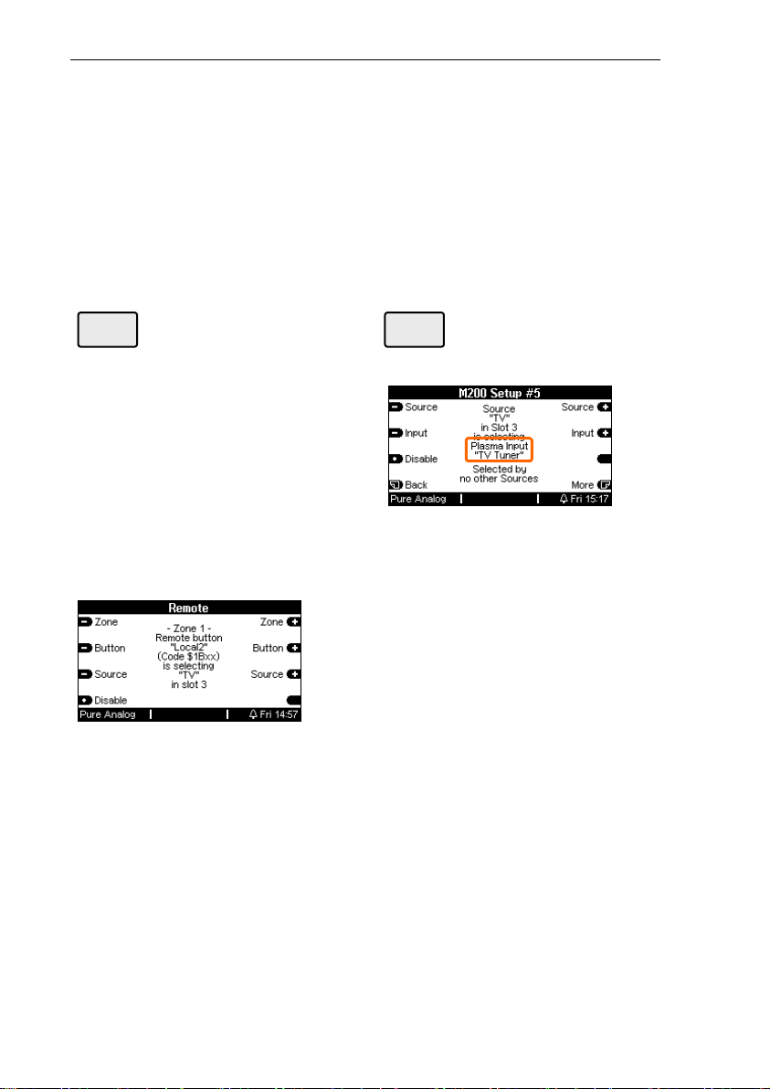
In the same way as with the
setup of an M51, you define
which video input at the Loewe
TV is activated by which M219
audio source, through the M203
Setup module. The local inputs
Local 1 – 3 at the M219 can be
used for the control, as well as
the audio sources of the Multi-
room Central unit.
Important advice:
If you want to use the soft-
ware version 2.00, the com-
plete Revox system must be
updated to the level 2.00, or
higher.

Introduction
M200 Mk2
The M200 Mk2 offers the option
of selecting specific stations
using the skip keys (<>) on an
M218 wall-mounted keypad,
once the TV tuner has been
selected.
This comfort function requires
two settings:
1/2 Audio IN assignment
M51 in combination with M200
The sound input, e.g. TV, Aux1,
Optical, etc., of the remote de-
vice must be assigned to one of
the following Remote buttons in
the Remote menu:
•Local
•Local 1
•Local 2
•Local 3
Assignment example
M219 in combination with M200
There is no need to make an
assignment through the Remote
menu with an M219, because its
local audio inputs (Local 1-3) are
always assigned to the IR com-
mands Local, Local 1, Local 2
and Local 3. Continue with point
2/2
Note: Monitor-only devices
This comfort function is only
available with TV models with an
integrated TV tuner. It cannot be
selected in case of monitor-only
devices without a TV tuner.
2/2 TV Tuner assignment
M200 Setup #5 - Input
The second assignment affects
Setup #5 in the M200. Here, the
physical audio source of the TV
sound that was assigned to a
Local Remote button in the first
step, is assigned to the televi-
sion's TV Tuner.
In the example above, the audio
source TV calls the television
tuner. As well as the Multiroom
central unit sources, a side room
amplifier also offers its own local
Inputs 1-3 for the TV Tuner as-
signment.
Switching between stations using the Revox wall-mounted keypad

Introduction
M200 Mk2
Function Overview
As well as main room operation,
the new side room functionality
available from software version
2.00 also allows an M200 Mk2 to
be connected to an M219 Side
room amplifier. You should be
aware however, that not all func-
tions are available in the side
room. This is highlighted in the
individual as well as in the follow-
ing overview table.
1 only in combination with an M-
Link booster – see drawings on
pages 14-16.
2 Relay control through the IR
remote control (Relay function:
Remote), is only possible if the
IR Receiver, e.g. M204, M208
is directly connected to the
M200 - see drawings on pages
14-16.
Function Re:system M51 Re:connect M219
Relay A/B
Yes1þ
Yes1+2
þ
Trigger Input A/B
Yes þ
No
o
Voltage Ramp 0-10 V
Yes þ
No
o
IR-Link Input
Yes þ
Yes2
þ
RS232 Control
Yes þ
Yes
þ

Installation & Connection
M200 Mk2
1
Installation
The two wood screws supplied
can be used for installing the
M200 Domotic Interface. As well
as the four external installation
holes, two lateral slotted holes
are available for a flexible instal-
lation.
Connection
You will find a detailed descrip-
tion of the various M200 inter-
face connection options on the
following pages.
Further Re:connect products: M201, M202, etc.
M-Link connection activity display
Serial interface activity display
RS232 seriell interface
Re:system (M51, M10) resp. Re:connect
Installation hole ∅4,2 mm
Slotted hole ∅4 x 20 mm / ∅15 mm
Trigger input A + B (IN 5-24V =)
Relay A + B (max. 42 Volt)
Variable voltage output (OUT 0-10V =)
IR input (M204, M218)
Setup button

Installation & Connection
M200 Mk2
2
Connection:
M200 with M51/ M219
Socket: M51 LINK IN
Setup: -
M219: Yes þ
The M200 interface is connected
with the M51 LINK socket on the
back of the M51 or the M219
LINK socket on the Side room
amplifier, using the supplied
telephone cable.
If you want to use a different
cable, you should only use a
non-crossed, 4-core telephone
cable with an RJ11 plug (6P4C
modular).
Max. cable length: 100 m
Max. cable resistance: 0.1 Ω /m
Connection:
M200 with external interfaces
Socket: M51 LINK OUT
Setup: -
M219: Yes þ
The M200 interface is designed
for the connection of further
external interfaces:
M51 operation
Currently, the following further
products can be connected with
the M51::
4M200 (2. interface)
4M201 IR interface
4M202 Ethernet interface
4M203 RS232 interface
4M217 Display
M219 operation
With the M219, the LINK OUT
can be used for the connection
of an M217 Display.
Use a non-crossed, 4-core
telephone cable with an RJ11
plug (6P4C modular).
Max. cable length: 100 m
Max. cable resistance: 0.1 Ω /m

Installation & Connection
M200 Mk2
3
Connection:
M200 with seriell interface
Socket: RS232
Setup: # 4 – from page 11
M219: Yes
þ
The M200 Interface can be used
with other (TV) devices, which
also have a serial interface.
This enables the integration of a
large number of Loewe televi-
sions into the Revox World.
Which models are supported
and how the integration is
achieved, is described starting
from page 11.
The M200 Interface is also suit-
able as an interface to domestic
facility management systems
such as AMX or Crestron,
which have a special Revox
protocol.
Even a Windows PC with the
M230 control program can be
connected to the serial interface
on the M200
Serial cables with a maximum
length of 10 metres can be
used.
Connection:
M200 Trigger input
Socket: INPUT A B RS232
Setup: # 4 – from page 6
M219: No
o
Using INPUT A and INPUT B,
you can trigger specific events at
the M51. This is done by apply-
ing a voltage between 5 and 24
volts (DC) to the corresponding
input. There are various options
that can be carried out when the
input is supplied with voltage.
This function is not available in
the side room through the M219.
Control example
The switching diagram below,
shows you how can activate the
Inputs A and B with two keys S1
and S2.
The voltage source is provided
by ⊕and Θon the IR-LINK.

Installation & Connection
M200 Mk2
4
Connection:
M200 Relay output
Socket: Relay A B
Setup: # 2 – from page 8
M219: Yes, with Link Booster þ
The two changeover relays can
be operated in different modes,
independently of each other.
Note:
In active operation, the relays
need 18-24 VDC. However when
connected to an M219 Side room
amplifier or when the M51 is in
standby mode, only 12 VDC is
available. This means that in
these cases, the relays do not
react to a command.
Solution:
Through the deployment of the
M-Link Booster, the power is
held at a permanent 18 VDC
and the relays work reliably in
every operational state – see
connection diagrams on pages
14-16.
Please note
The switching voltage may
not exceed 42 volts.
Switching voltage: 0- 42 Volt*
Max. switching current: 4-8 A*
* dependent on load -See Technical data
Connection:
M200 Voltage ramp
Socket: Output
Setup: without configuration
M219: No o
Using the OUTPUT, you can
control the output voltage with
the remote control M208, giving
a variable voltage between 0
and 10 volts. This voltage ramp
could be used, for example, to
set the dimmer control of a light-
ing system to a desired level.
Standard electronic dimmers
with a controller input offer the
option of adjusting the bright-
ness between 0 and 100%.
Functions:
- On (with memory function)
- Off
- Increase voltage
- Decrease voltage
- 10 fixed voltage levels
i
The remote unit control file for
the voltage output at the M200 is
located in the M208 Project
Manager device library, under
the heading Revox – Revox
Domotic M200. All deployed
RC5 codes are stored in this file.

Installation & Connection
M200 Mk2
5
Connection:
M200 with IR controller
Socket: IR-Link
Setup: # 3 – from page 9
M219: Yes þ
The connection to an IR receiver
or a wall-mounted remote con-
trol is done through the 3-pin,
screw-fixable Phoenix plug con-
nection.
Revox recommends the use of a
2-core screened cable (micro-
phone cable), where the screen-
ing is used as ground. This ca-
ble may be a maximum of 30
metres in length.
Please ensure that you use the
correct polarity when setting up
as otherwise you might damage
your equipment.
Symbols:
+àPos. voltage. 12-20V (DC)
IN àIR Signal
-àGround
Important
Relay control through the IR re-
mote control (Relay function: Re-
mote), is only possible if the IR
Receiver, e.g. M204, M208 is
directly connected to the M200
through the IR Link - see draw-
ings on pages 14-16.
The maximum number of IR
receivers that can be switched in
parallel per M200 is 3.

Configuration
M200 Mk2
6
Setup Button
Using the Setup key, you call up
the M200 menu, which is shown
in the M51 display.
If the M200 interface is connected
with an M219 Side room amplifier,
the M51 display is also used.
In the case of an M10 installation,
display is done using the M230
service program or M-Scope.
Using the Softkeys
you can get to pages #1 till #5.
Setup page #5 only appears if a
video device has been selected
on page #4 as Serial Port Mode.
Setup #1 – Control Input
Function: Trigger input
Display: Control Input A/B
Connection: Input A/B -page 4
M219: No o
Using INPUT A and INPUT B,
you can trigger specific events
at the M51.
The required option can be se-
lected from an option loop by
pressing the Input und Input
softkeys.
DVD/CD
Tuner
Tape
Aux 1-3
Local
TV
Video 1-6
Power On
Power Off
System Off
Mute (Toggle)*
Light Dimmer
Not Used

Configuration
M200 Mk2
7
DVD/CD - TV
M51 is switched on with and/or
switches over to the correspond-
ing source.
Power On:
Switches the M51 on with the
last activated source.
Power Off
Switches the M51 off.
System Off
Switches the complete system
off, including any side rooms.
Mute (Toggle)
This toggles the mute function of
the M51 and is only possible in
conjunction with the 5.1 Decoder
Module MK 2 or 3.
Light Dimmer
Activates the voltage output
dimmer function (Output 0-10V)
with Toggle-Automatic.
Not Used
Deactivates the corresponding
input.
Please note
When you are selecting the
source, you should be aware
that the source that has been
assigned to the corresponding
button in the Remote menu will
be selected. If a source is dis-
abled through the Remote
menu, it will not be activated,
even when it is selected in the
input option.
Further information on this topic
can be found in the M51 Operat-
ing Manual in the Introduction
chapter, in the description of the
remote function.
ð

Configuration
M200 Mk2
8
Setup #2 – Relay
Function: Relay output
Display: Func. Relays A/B
Connection: Relay -page 4
M219: Yes, with Link
Booster þ
The two relays each offer 5 op-
tions that can be selected with
the Input and Input soft-
keys.
The required option can be se-
lected from an option loop:
Please note
The switching voltage may
not exceed 42 volts.
Switching voltage: 0- 42 Volt*
Max. switching current: 4-8 A*
* dependent on load - See Technical data
Relay Functions
Remote
The relays are controlled over IR
commands (M208) with Re-
mote. This function is only
available if a Link Booster is
installed upstream of the M200.
iM219 - Cabling
The IR Receiver must be con-
nected directly with the M200.
See Connection plan on page
14.
Open
The relay is in idle state
Close
The relay is energised.
Power On/Off
If the M51/ M219 is switched on,
the relay is energised. In standby
mode, the relay is in idle state.
TV-Lift
The relay is energised depend-
ent on a selected M51 audio
source. The decision is made by
the assignment of a video
source to an audio source on
page #5 of the M200 Setup
This function can be used to roll
out a projector screen or to acti-
vate a TV lift.
At the same time, the correct
video device input can be con-
trolled through the serial inter-
face.
Remote
Open
Close
Power On/Off
TV-Lift

Configuration
M200 Mk2
9
Setup #3 – IR-Address
Function: IR Address
Display: Remote Address
Connection: -
M219: Yes þ
The relay and dimmer functions
can be controlled through the
remote control and/or a con-
nected M218 wall-mounted op-
erating panel.
Through the selection of the
(RC5-) remote address, you can
define whether the relay and
dimmer functions should be
operated from the remote con-
trol and the wall-mounted opera-
tor panel or whether only one of
them should be accepted.
Address Transmitter
Light (30) Remote control
Local (19)
Wall mounted
remote control
Both (30+19) Combination
i
The remote address has no rela-
tionship to the slot address,
which the M200 uses to register
with the M51/ M219.
Setup #3 – Source
Function: IR receiver
Display: Remote Source
Connection: inc. IR-Link - page 5
M219: No o
Selection of the (IR) sources
that the M200 interface accepts
for dimming and relay functions
as data suppliers.
This M-200 only
Accepts only sources that are
directly connected to the M200’s
IR Link, e.g.. MR204 or M218
wall-mounted remote control.
All Receivers
All sources are accepted as data
suppliers, e.g. also a M51 or an
additional M200 interface.
This setting has no effect in the
case of a side room installation
with an M219.

Configuration
M200 Mk2
10
Setup #4 a) Slot M51
Function: Addr. assignment
Display: Slot Address
Connection: M51-Link – page 2
M219: Yes þ
M51 operation –fig. page 15
If a second M200 (M203) is
connected to the M51 Link out-
put, a different address must be
assigned through the slot selection
so that both M200s don’t occupy
the same slot address. This would
cause errors. In the case of a dou-
ble assignment, neither of the two
M200s would be shown in the M51
Version list.
Slot Address : #11 or #12
The two slot addresses 11 and 12
are available for selection. The
following message appears (Dis-
play:#xx occupied) if the selected
address is already assigned:
Setup #4 b) Slot M219
M219 operation -fig. page 13
In respect of the M219, the slot
address defines the assignment to
the Side room amplifier. A M200
can only be connected to an Side
room amplifier within the address
range x1 – x4.
The slot address defines which
Side room amplifier the M200
interface should communicate
with. This is necessary because of
the bus system, although in each
case, the M200 is individually con-
nected with the M219. Only one
M200 interface can be used per
Side room amplifier.
Address assignment : Zone 1-4
M219/ 217 M200/ M203
x 1 ðx 11
x 2 ðx 12
x 3 ðx 13
x 4 ðx 14
x 5
x 6
x 7
x 8
x 1 – x 4: only M219
x 5 – x 8: M217 or M219
x 11 – x 14: only M200 / M203

Configuration
M200 Mk2
11
Example
In Figure A, an M200 could be
connected to each of the Side
room amplifiers 31 – 34. The M219
amplifiers 35 and 38 on the other
hand may not be connected with
an M200 interface.
Fig A. Multiroom version list / Zone 3
The figure below shows the Multi-
room version list from Zone 3 for
the M200 interfaces. You get to
this menu by repeatedly pressing
the Zone softkey in the sub-menu
(M51, M230 etc.) of: Setup ð
Multiroom ðVersion
ðZone x
In this case, an M200 interface
was assigned to the Side room
amplifier with address 4, through
the slot address 314. Amplifiers 1
– 3 do not have an M200.
Fig B. Multiroom version list / Zone 3
Setup #4 – RS232 Modus
Function: RS232 interface
Display: Serial Port Mode
Connection: RS232 – page 3
M219: Yes þ
The function of the serial inter-
face (Serial Port) can be con-
figured for the following applica-
tions:
•RS-232 Link
•RS-232 Filtered
•Gefen HDMI Switcher 4x2, 4x1
•Gefen HDMI Switcher 6x2
•Loewe L27xx 1
•Loewe SL1xx2
•Loewe SL2xx2
•Loewe SL3xx2
1All Loewe televisions with chassis
electronics L2700* or higher.
In order to ensure problem-free
operation, the Loewe TVs must
meet the following requirements:
Loewe TV Service Menu: System data
TV application software version:≥V2.2.x
Firmware I2CUART version: ≥V3.1.x
2 Requires the latest software, at
least from June 2016.
Please take note of the impor-
tant information on page 13
relating to a complete reset of
the M200.

Configuration
M200 Mk2
12
Setup #4 –Auto Standby
Function: Auto Standby
Display: Auto Standby
Connection: RS232 – page 3
M219: Yes þ
The Auto Standby function
enables the TV to remain
switched on, even in the case of
selected audio sources that do
not activate a video input at the
TV, e.g. the M51 radio tuner.
The Auto Standby option is only
shown in the menu if the Loewe
model has been selected as Serial
Port Mode.
Auto Standby: ON
The Loewe TV switches itself off
automatically as soon as an audio
source is selected, which either
cannot activate a video input, e.g.
Tuner, or which is disabled
Auto Standby: OFF
After the Loewe TV has been
switched on, it remains on perma-
nently until the M51/ M219 is
switched off, irrespective of which
audio source is selected.
RS-232 Link.
Standardised serial interface
(RS232 protocol) for connection
to a PC or another serial inter-
face.
Application:
You should select this setting if
you want to use the M230 con-
trol program for PCs or if you
want to access the Revox Sys-
tem through domestic facility
management equipment such as
Crestron and AMX.
RS-232 Filtered.
Data-reduced RS232 protocol.
Only M51-specific data is trans-
ferred, so-called display and
broadcast messages.
Application:
Simple controllers with low data
traffic requirements.

Configuration
M200 Mk2
13
Video Controller
If a video controller for a Loewe
TV was selected on page #4
Port Mode, a second menu
page, Setup # 5 is available.
This page enables you to selec-
tively switch on and/or between
video inputs on a Loewe TV or
an HDMI Switcher from the Ge-
fen company, dependant on the
selected M51/ M219 source.
Example M200 with M51:
A SAT receiver can conveniently
be integrated through the auto-
matic selection of the video input
on the TV by the M51. Its picture
output is connected, for example,
to the Input-2 on the Loewe TV,
while the audio signal is con-
nected to the Optical digital input
on the M51.
Please also refer to the picture on
the next page.
If you now select the source SAT
(Optical) at the M51, the Loewe
TV automatically transmits the
SAT receiver picture over the
Input-2 and the sound from the
SAT receiver is transmitted over
the M51.
The convenient integration can
of course also be used for the
M51’s integrated DVD player.
Please refer to the picture on the
next page – Connection : Video
1).
The audio source and video
input links referred to in the ex-
ample are defined in Setup #5.
You will find an exact description
of the links, starting from page 21.
Complete reset?
Yes
You should always carry out a
complete reset with each new
configuration as well as when
changing to another TV model.
To do this, press the Disable
softkey on Setup page #2 and
keep it pressed, until the system
automatically returns you to
page 1.
No
A complete reset is not necessary
with an assignment change within
a TV model.
This manual suits for next models
1
Table of contents
Other Revox Recording Equipment manuals