Wasco EXDUL-392E User manual

Handbuch
wasco®
user‘s guide
wasco®
EXDUL-392E
EDP-No: A-382220
4 A/D inputs 16-bit (single ended) or
2 A/D inputs16 Bit (differential)
2 current A/D inputs15 Bit
1 optocoupler isolated digital input
1 optocoupler isolated digital output
3 temperature measuring units
1 counter 32 bit
LCD display (EXDUL-392E only
EXDUL-392S
EDP-No: 382210
EXDUL-392E
EDV-Nr.: A-382220
EXDUL-392S
EDV-Nr.: A-382210
4 A/D-Eingänge 16 Bit (single-ended) oder
2 A/D-Eingänge 16 Bit (differentiell)
2 Strom A/D-Eingänge 15-bit
1 Eingang über Optokoppler
1 Ausgang über Optokoppler
3 Temperaturmesseinheiten
1 Zähler 32 Bit
LCD-Anzeige (nur EXDUL-392E)

2
EXDUL-392E / EXDUL-392S© 2019 by Messcomp Datentechnik GmbH DV01
2
EXDUL-392E / EXDUL-392S© 2019 by Messcomp Datentechnik GmbH EV03
wasco®wasco®
Copyright©2019 by Messcomp Datentechnik GmbH
Diese Dokumentation ist urheberrechtlich geschützt. Alle Rechte sind
vorbehalten.
Messcomp Datentechnik GmbH behält sich das Recht vor, die in dieser
DokumentationbeschriebenenProduktejederzeitundohneVorankündigung
zu verändern.
OhneschriftlicheGenehmigungderFirmaMesscompDatentechnikGmbH
darf diese Dokumentation in keinerlei Form vervielfältigt werden.
Geschützte Warenzeichen
Windows®, Visual Basic®, Visual C++®, Visual C#®sind eingetragene
Warenzeichen von Microsoft.
wasco®ist ein eingetragenes Warenzeichen.
EXDUL®ist ein eingetragenes Warenzeichen.
Haftungsbeschränkung
Die Firma Messcomp Datentechnik GmbH haftet für keinerlei durch den
GebrauchdesMultifunktionsmodulsEXDUL-392unddieserDokumentation
direkt oder indirekt entstandenen Schäden.
Wichtiger Hinweis:
Dieses Handbuch wurde für die Module EXDUL-392E und EXDUL-392S
erstellt. Das EXDUL-392E bietet zusätzlich eine LCD-Anzeige, alle wei-
terenFunktionenderModulesindidentisch.FürdasEXDUL-392Ssinddie
Befehle und Funktionen, die das Display betreffen, nicht zutreffend.
Copyright©2019 by Messcomp Datentechnik GmbH
This documentation is copyright by Messcomp Datentechnik GmbH. All
rights are reserved.
Messcomp Datentechnik GmbH reserves the right to modify the products
described in this manual at any time and without preannouncement.
No parts of this manual are allowed to be reproduced, copied, translated
or transmitted in any way without prior written consent of Messcomp
Datentechnik GmbH.
Registered Trademarks
Windows®, Visual Basic®, Visual C++®, Visual C#®are registered trade-
marks of Microsoft.
wasco®is registered trademark.
EXDUL®is registered trademark.
Disclaimer
Theinformation inthis manualis intendedto beaccurate andreliable. The
companyMesscompDatentechnikGmbHdoesnotassumeanyliabilityfor
anydamagesarisingoutoftheuseoftheA/DconvertermoduleEXDUL-392
and this documentation, neither for direct nor indirect damages.
Important Information:
ThismanualwasmadeupforthemodulesEXDUL-392EandEXDUL-392S.
EXDUL-392E additionally provides an LCD display, all other functions
are exactly the same. For the EXDUL-392S all commands and functions
concerning the LCD display are not applicable.

3
EXDUL-392E / EXDUL-392S© 2019 by Messcomp Datentechnik GmbH DV01
3
EXDUL-392E / EXDUL-392S© 2019 by Messcomp Datentechnik GmbH EV03
wasco®wasco®
Table of Contents Inhaltsverzeichnis
1. Introduction.......................................................................................5
2. Connection Terminals......................................................................6
2.1 Terminal Assignments of CN1 ...............................................................................6
3. System Components........................................................................7
3.1 Block Diagram EXDUL-392E.................................................................................7
3.2 Block Diagram EXDUL-392S.................................................................................8
3.3 A/D Inputs Voltage.................................................................................................9
3.4 A/D Inputs Current.................................................................................................9
3.5 Optocoupler Input..................................................................................................9
3.6 Digital Output Optocoupler Isolated.....................................................................10
3.7 Counter................................................................................................................10
3.8 Temperature Measuring Units .............................................................................10
3.9 LCD Display (EXDUL-392E only)........................................................................10
4. Commissioning ..............................................................................11
4.1 Connecting to a USB Port ..................................................................................11
4.2 Power Supply via USB Port.................................................................................11
4.3 External Power Supply........................................................................................11
4.4 LCD Display during Commissioning (EXDUL-392E only) ...................................11
4.5 LCD display during operating (EXDUL-392E only)..............................................12
5. A/D Inputs Measuring Current or Voltage ....................................13
5.1 Voltage Measurement..........................................................................................13
5.2 Current Measurement..........................................................................................18
5.3 Modes of Measurements.....................................................................................19
6. 3 Temperature Measurement Units PT100 ...................................21
6.1 Circuitry ...............................................................................................................21
6.2 Measurement Options.........................................................................................22
6.3 Error Detection ....................................................................................................22
7. One Optocoupler Input ..................................................................24
7.1 Pin assignment of the input optocoupler .............................................................24
7.2 Input Circuitry ......................................................................................................25
7.3 Input Current........................................................................................................25

4
EXDUL-392E / EXDUL-392S© 2019 by Messcomp Datentechnik GmbH DV01
4
EXDUL-392E / EXDUL-392S© 2019 by Messcomp Datentechnik GmbH EV03
wasco®wasco®
8. One Optically Isolated Output........................................................26
8.1 Pin assignment of the output optocoupler...........................................................26
8.2 Optocoupler specications ..................................................................................26
8.3 Output circuitry ....................................................................................................26
9. Installation of the Windows®Drivers............................................27
10. Programming on Windows® .................................................................................................... 28
10.1 Introduction........................................................................................................28
10.2 Communication with EXDUL-392......................................................................28
10.3 Windows®Functions for Programming..............................................................29
10.4 Register HW Identication and Serial Number..................................................29
10.5 Memory Spaces UserA, UserB, UserLCD1m* and UserLCD2m*.....................30
10.6 Display Register UserLCD-line1*, UserLCD-line2* and LCD Contrast*............30
10.7 Command and Data Format..............................................................................31
10.8 Command Overview..........................................................................................31
10.9 Structure of Commands.....................................................................................32
11. Specications ...............................................................................60
12. Circuitry Examples.......................................................................62
12.1 Wiring of the Optocoupler Input.........................................................................62
12.1 Beschaltung des Optokoppler-Eingangs...........................................................62
12.2 Wiring of the Optocoupler Output......................................................................63
12.3 Wiring of the A/D Inputs single ended (voltage) ................................................64
12.4 Wiring of the A/D Inputs differential (voltage)....................................................65
12.5 Wiring of the A/D Inputs current measurement..................................................66
12.6 Wiring of the A/D Inputs Voltage or Current Measurement................................67
13. ASCII Table.....................................................................................68
14. Product Liability Act.....................................................................71
15. CE Declaration of Conformity .....................................................73

5
EXDUL-392E / EXDUL-392S© 2019 by Messcomp Datentechnik GmbH DV01
5
EXDUL-392E / EXDUL-392S© 2019 by Messcomp Datentechnik GmbH EV03
wasco®wasco®
1. Introduction 1. Produktbeschreibung
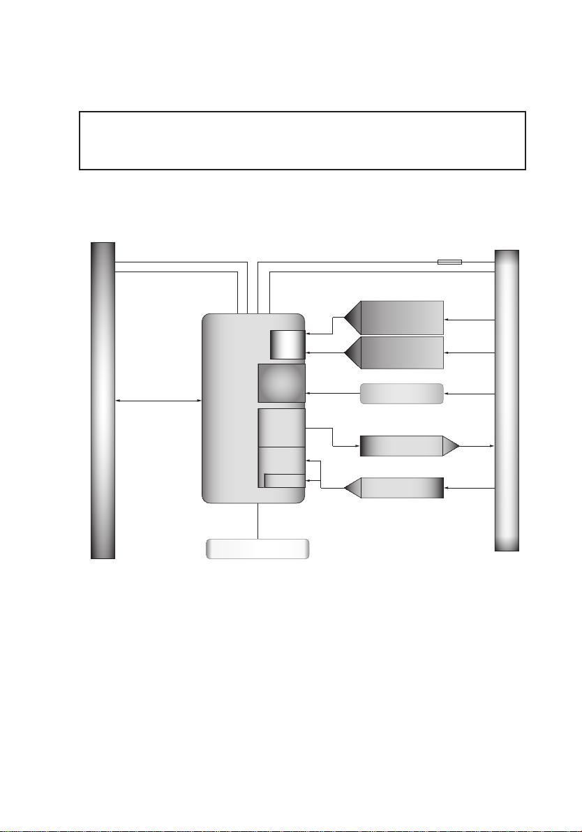
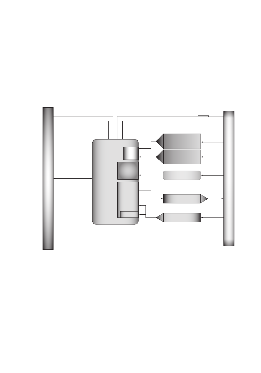
Das EXDUL-392 verfügt über vier massebezogene oder zwei
differentielle 16-Bit A/D-Spannungs-Eingangskanäle mit bipolaren
Eingangsspannungsbereichen (+/-0,63 V, +/-1,27 V, +/-2.55V, +/-5.1
V, +/-10.2 V), sowie über 2 bipolare Stromeingänge (+/-20mA), welche
auf 4..20mA abgeglichen sind. Für die Temperaturmessungen mit
PT100-Sensoren besitzt das Modul 3 Messeinheiten mit jeweils eigener
Stromquelle und Messeingängen. Die Wandlungsauslösung inklusive
der damit verbundenen Konguration der A/D-Komponenten (Bereich-/
Kanalauswahl) erfolgt per Software-Befehl. Zusätzlich verfügt das Modul
übereinendigitalenEingangundeinendigitalenAusgangmitgalvanischer
Trennung über hochwertige Optokoppler und zusätzlichen Schutzdioden.
DerOptokopplereingangkannbeiBedarfals32-Bit-Zählereingangprogram-
miertundgenutztwerden.SpezielleleistungsfähigeAusgangsoptokoppler
bewältigen einen Schaltstrom von bis zu 150 mA.
Die programmierbare LCD-Anzeige beim EXDUL-392E ermöglicht die
Darstellung von digitalen und analogen I/O-Statusinformationen oder
programmierbaren anwenderspezischen Daten.
Über USB oder eine externe Spannungquelle wird das Modul mit
der notwendigen Betriebsspannung versorgt. Die Anschlüsse für die
Spannungsversorgung sind wie die Anschlüsse des Eingangs- und
Ausgangsoptokopplers einer 24poligen Schraubklemmleiste zugeführt.
DaskompakteGehäuseerlaubtdenEinsatzalsmobilesModulamNotebook
sowie als Steuermodul im Steuerungs- und Maschinenbau mit einfacher
Wandmontage oder unkomplizierter Montage auf DIN EN-Tragschienen.
EXDUL-392provideseitherfourgroundreferencedortwodifferential16-bit
A/D input channels and two bipolar current inputs (+/-20mA), which are
calibrated to 4..20mA. You can adjust several bipolar input voltage ranges
(+/-0.63 V, +/-1.27 V, +/-2.55 V, +/-5.1 V, +/-10.2 V). For temperature mea-
surementswithPT100sensors,themodulefeaturesthreemeasuringunits,
each with its own current source and measuring inputs.The conversion
process including the associated conguration of the A/D components
(selection of range and channel) is triggered by software commands.
Additionally the module provides one digital input and one digital output
galvanically opto-isolated by high-quality optocouplers and additional
protection diodes. If necessary, the optocoupler input can be programmed
andused asacounter input.Specialhigh poweroutputoptocouplers cope
with a switching current up to 150 mA.
The programmable LCD display of the EXDUL-392E shows either digital
or analog I/O status information or programmable user-specic data.
The module is powered with the necessary operating voltage by USB or
byan externalpowersupply.The moduleprovidesa 24-pinscrew terminal
block for connecting the external power supply as well as the input and
output optocoupler.
The compact casing enables the module to be used as a portable device
withanotebook.Formechanicalorcontrolengineeringitcanalsobeeasily
wall mounted or attached to DIN mounting rail.

6
EXDUL-392E / EXDUL-392S© 2019 by Messcomp Datentechnik GmbH DV01
6
EXDUL-392E / EXDUL-392S© 2019 by Messcomp Datentechnik GmbH EV03
wasco®wasco®
2. Connection Terminals
2.1 Terminal Assignments of CN1
Vcc_EXT:
Connector for external voltage source
GND_EXT:
Ground connection when using external voltage source
2. Anschlussklemmen
Vcc_EXT:
Anschlussklemme für externe Versorgungsspannung
GND_EXT:
Masse-Anschluss bei Verwendung einer externen Versorgungsspannung
2.1 Klemmenbelegung von CN1
1
3
5
7
9
11
13
15
17
19
21
23
AINU0+
AINU2+
AINI0+
AINI1+
RTDIN2+
AGND
DOUT0+
DIN0+
Vcc_EXT
2
4
6
8
10
12
14
16
18
20
22
24
AINU1+
AINU3+
AINI0-
AINI1-
FORCE0+
FORCE2-
DOUT0-
DIN0-
GND_EXT
FORCE0-
RTDIN1+
RTDIN0+
FORCE1+
FORCE1-
FORCE2+
1
3
5
7
9
11
13
15
17
19
21
23
AINU0+
AINU2+
AINI0+
AINI1+
RTDIN2+
AGND
DOUT0+
DIN0+
Vcc_EXT
2
4
6
8
10
12
14
16
18
20
22
24
AINU1+
AINU3+
AINI0-
AINI1-
FORCE0+
FORCE2-
DOUT0-
DIN0-
GND_EXT
FORCE0-
RTDIN1+
RTDIN0+
FORCE1+
FORCE1-
FORCE2+

7
EXDUL-392E / EXDUL-392S© 2019 by Messcomp Datentechnik GmbH DV01
7
EXDUL-392E / EXDUL-392S© 2019 by Messcomp Datentechnik GmbH EV03
wasco®wasco®
3.1 Block Diagram EXDUL-392E
3. System Components
FIFO
24pin Screw Terminal
GND
Controller
USB Connector
ext. Vcc +10V...+30V
GND
+5V
Optocoupler Output
DOUT
IN
OUT
Optocoupler Input
DIN
16 Bit A/D Converter
Voltage Measurement
AINU0 - AINU3
Counter
16 Bit A/D Converter
Current Measurement
AINI0 - AINI1
PT100
Temperature Measurement
TIN0 ... TIN2
Display
3.1 Blockschaltbild EXDUL-392E
3. Systemkomponenten
Fig. 3.1 Block diagram EXDUL-392E Grak 3.1 Blockschaltbild EXDUL-392E
FIFO
24polige Schraubklemmleiste
GND
Controller
USB Connector
ext. Vcc +10V...+30V
GND
+5V
Optokopplerausgang
DOUT
IN
OUT
Optokopplereingang
DIN
16 Bit A/D-Wandler
Spannungsmessung
AINU0 - AINU3
Zähler
Display
16 Bit A/D-Wandler
Strommessung
AINI0 - AINI1
PT100
Temperaturmessung
TIN0 ... TIN2

8
EXDUL-392E / EXDUL-392S© 2019 by Messcomp Datentechnik GmbH DV01
8
EXDUL-392E / EXDUL-392S© 2019 by Messcomp Datentechnik GmbH EV03
wasco®wasco®
3.2 Block Diagram EXDUL-392S
FIFO
24pin Screw Terminal
GND
Controller
USB Connector
ext. Vcc +10V...+30V
GND
+5V
Optocoupler Output
DOUT
IN
OUT
Optocoupler Input
DIN
16 Bit A/D Converter
Voltage Measurement
AINU0 - AINU3
Counter
16 Bit A/D Converter
Current Measurement
AINI0 - AINI1
PT100
Temperature Measurement
TIN0 ... TIN2
3.2 Blockschaltbild EXDUL-392S
Fig. 3.2 Block diagram EXDUL-392S Grak 3.2 Blockschaltbild EXDUL-392S
FIFO
24polige Schraubklemmleiste
GND
Controller
USB Connector
ext. Vcc +10V...+30V
GND
+5V
Optokopplerausgang
DOUT
IN
OUT
Optokopplereingang
DIN
16 Bit A/D-Wandler
Spannungsmessung
AINU0 - AINU3
Zähler
16 Bit A/D-Wandler
Strommessung
AINI0 - AINI1
PT100
Temperaturmessung
TIN0 ... TIN2

9
EXDUL-392E / EXDUL-392S© 2019 by Messcomp Datentechnik GmbH DV01
9
EXDUL-392E / EXDUL-392S© 2019 by Messcomp Datentechnik GmbH EV03
wasco®wasco®
3.3 A/D-Eingänge Spannung
4 Eingänge single-ended (se)
oder 4 Eingänge differentiell (diff)
oder kombiniert se/diff per SW wählbar
Auösung: 16 Bit
Eingangsspannungsbereich bipolar
+/-0,63 Volt, +/-1,27 Volt, +/-2,55 Volt, +/-5.1 Volt, +/-10.2 Volt
FIFO: 10000 Messwerte
Eingangswiderstand: 500 MΩ
Überspannungsschutz: 50V
max. Abtastrate: 100kHz
3.4 A/D-Eingänge Strom
2 Eingänge
Auösung 15 Bit
Messbereich +/-20mA
Abgeglichen auf 4..20mA
Eingangswiderstand 120Ω
FIFO: 10000 Messwerte
max. Abtastrate: 100kHz
3.5 Digitaler Eingang über Optokoppler
1 bipolarer Kanal
Überspannungsschutz-Dioden
Eingangsspannungsbereich
high = 10..30 Volt
low = 0..3 Volt
3.3 A/D Inputs Voltage
4 inputs single-ended (se)
or 2 inputs differential (diff)
or combined se/diff software-selectable
Resolution: 16 bit
Input voltage ranges bipolar:
+/-0.63 V, +/-1.27 V, +/-2.55 V, +/-5.1 V, +/-10.2 V,
+/-20.4 V (differential inputs only)
FIFO: 10,000 measuring values
Input resistance: > 500 MΩ
Over voltage protection: 50V
Sampling rate: max 100 kHz
3.4 A/D Inputs Current
2 inputs
Resolution: 15 bit
Measuring range +/- 20mA
Calibrated to 4..20mA
Input resistance: 120 MΩ
FIFO: 10,000 measuring values
Sampling rate: max 100 kHz
3.5 Optocoupler Input
1 bipolar channel
Over voltage protection diodes
Input voltage range
high = 10..30 Volt
low = 0..3 Volt

10
EXDUL-392E / EXDUL-392S© 2019 by Messcomp Datentechnik GmbH DV01
10
EXDUL-392E / EXDUL-392S© 2019 by Messcomp Datentechnik GmbH EV03
wasco®wasco®
3.6 Digitaler Ausgang über Optokoppler
1 Kanal
Leistungsoptokoppler
Verpolungsschutz-Dioden
Ausgangsstrom: max. 150 mA
Spannung-CE: max. 50 V
3.7 Zähler
1 programmierbarer Zähler 32 Bit (belegt den Optokoppler-Eingang)
Zählfrequenz: max. 5 kHz
3.8 3 Temperaturmesseinheiten PT100
3-Leiteranschluss
3.9 LCD Anzeige (nur EXDUL-392E)
Matrixanzeigemit 2Zeilen und16 Spaltenzur Darstellungvon 16Zeichen
je Zeile
Programmierbar zur Darstellung anwendungsspezischer Daten oder als
I/O-Zustandsanzeige
3.6 Digital Output Optocoupler Isolated
1 channel
High capacity optocoupler
Reverse polarity protection
Output current: max. 150 mA
Switching voltage: max. 50 V
3.7 Counter
1 programmable counter 32 bit (allocated to the optocoupler input)
Counting frequency: max. 5 kHz
3.8 Temperature Measuring Units
3-wire sensing
3.9 LCD Display (EXDUL-392E only)
Matrix display with 2 lines and 16 columns displaying 16 characters each
line
Programmable to display customized data or I/O state

11
EXDUL-392E / EXDUL-392S© 2019 by Messcomp Datentechnik GmbH DV01
11
EXDUL-392E / EXDUL-392S© 2019 by Messcomp Datentechnik GmbH EV03
wasco®wasco®
4. Commissioning 4. Inbetriebnahme
DerPC-Anschluss erfolgteinfach undunkompliziert Plug&Play übereine
USB-Schnittstelle.ÜberUSBodereineexterneSpannungsquellewirddas
Modul mit der notwendigen Betriebsspannung versorgt.
4.1 Anschluss an einen USB-Port
Das EXDUL-392E / EXDUL-392S verfügt über ein USB 2.0 Interface und
wird über die beiliegende USB-Anschlussleitung direkt an einen PC oder
an einen USB-Hub angeschlossen. Der Anschluss erfolgt hotpluggable,
d.h. das Modul ist auch im laufenden Betrieb anschließbar.
4.2 Spannungsversorgung über den USB-Port
DasModulEXDUL-392kannbeiBedarfohneEinschränkungenausschließ-
lichüberdie USB-Schnittstelleversorgt werden.Dafür musssichergestellt
werden, dass der PC über das USB-Interface 500mA liefern kann.
4.3 Spannungsversorgung über externe Spannungsquelle
Die Firmware des EXDUL-392E / EXDUL-392S erkennt selbständig die
Spannungsversorgung über eine externe Spannungsquelle. Wird an
den Klemmen Vcc_EXT und GND_EXT (siehe Klemmenbelegung) eine
Spannung von +10 V...+30 V DC angelegt, schaltet das Modul sofort auf
Betriebsspannung„extern“um.DieSpannungsversorgungüberdenUSB-
Port wird automatisch unterbrochen.
Achtung: Die Spannungsversorgung des Moduls darf während des Betriebs
nicht mehr gewechselt werden!
4.4 LCD-Anzeige während der Inbetriebnahme (nur EXDUL-392E)
Während der Inbetriebnahme bzw. Start des Moduls erscheint im Display
eine Infoanzeige in Form des Modulnamens. Nach fünf Sekunden wird
der Modulname je nach LCD-Anzeigen-Konguration entweder durch die
I/O-Statusanzeige oder UserLCD-Anzeige ersetzt.
ConnectingtoacomputerismadesimpleanduncomplicatedinaPlug-and-
Play manner via USB interface. The module is powered with the required
operating voltage via USB port or via an external voltage source.
4.1 Connecting to a USB Port
TheEXDUL-392E/EXDUL-392SprovidesaUSB2.0interfaceandcanbe
connecteddirectlytothecomputerortoaUSBhubusingtheenclosedUSB
connecting cable. The connection supports hot-plug function, that means,
it is possible to connect the module even during the system is operating.
4.2 Power Supply via USB Port
If required, it is possible to power the module EXDUL-392 via the USB
port exclusively without limitations. For this, it must be ensured that the
computer is able to supply 500mA via the USB interface.
4.3 External Power Supply
EXDUL-392E / EXDUL-392S rmware automatically detects when an
external voltage source is connected. Applying a voltage between +10V
and +30 V across Vcc_EXT and GND_EXT (see gure terminal assign-
ments) immediately causes the device to switch to „external“ source. The
power supply from the USB port is automatically interrupted.
Attention: You must not change the mode of power supply during
operation!
4.4 LCD Display during Commissioning (EXDUL-392E only)
During commissioning or at start of the module, the display shows an
information representing the module name. After 5 seconds, the module
name is replaced by either by I/O status display or UserLCD display,
depending on the LCD display conguration.

12
EXDUL-392E / EXDUL-392S© 2019 by Messcomp Datentechnik GmbH DV01
12
EXDUL-392E / EXDUL-392S© 2019 by Messcomp Datentechnik GmbH EV03
wasco®wasco®
4.5 LCD-Anzeige während des Betriebs (nur EXDUL-392E)
Bei der Inbetriebnahme des Moduls schaltet das Display nach ca.
fünf Sekunden, je nach Einstellung, von der Infoanzeige in die I/O-
Statusanzeige oder die UserLCD-Anzeige. Während der I/O-Anzeige
werden in Zeile1 die aktuellen Zustände der Eingänge, in Zeile2 die
ZuständederAusgängeangezeigt.FallsbeimletztenBetriebdesModuls
mitvorgesehenemBefehlderUserLCD-Modusaktiviertwurde,erscheint
anstellederI/O-StatusanzeigedieUserLCD-AnzeigemitdenWertenaus
den Speicherbereichen UserLCD1m und UserLCD2m. Die Daten aus
denbeidenRegisternwerdensolangeangezeigt,bisneueBenutzerdaten
überUserLCD-Zeile1undUserLCD-Zeile2aufdieAnzeigegeschrieben
werden. Um einen „Screen-Burn“ zu vermeiden, wechselt die Anzeige
im laufenden Betrieb etwa jede Minute für ca. fünf Sekunden von der
I/O-Statusanzeige oder UserLCD-Anzeige in die Infoanzeige.
4.5 LCD display during operating (EXDUL-392E only)
Starting the module the display switches from the info display to the
digital I/O status display or the UserLCD display after approx. ve se-
conds depending on the LCD display conguration. When I/O status
display is selected, line1 shows the current input states, line2 the out-
put states. If the UserLCD modus was activated by calling the intended
command before the last shutdown of the system, the values from the
memory areas UserLCD1m and UserLCD2m are shown instead of the
I/O status display. Data from both of the registers are displayed until
new user data is written to the display UserLCD line1 and UserLCD
line2. To avoid „screen-burn“ while in operation the display switches
from I/O status or UserLCD display to info display for approximately
ve seconds every minute.

13
EXDUL-392E / EXDUL-392S© 2019 by Messcomp Datentechnik GmbH DV01
13
EXDUL-392E / EXDUL-392S© 2019 by Messcomp Datentechnik GmbH EV03
wasco®wasco®
5. A/D Inputs Measuring Current or Voltage
The EXDUL-392 provides 4 multiplexed single ended or 2 differential
16-bitA/D input channels with programmable input voltage range and two
16-bit A/D current input channels. When the conversion is triggered, the
computer will transfer conguration data for conversion (channel, range)
in the form of two bytes. After error corrections (such as offset errors) the
moduletransmitsthe measuredvalue transformedin avoltage valuein µV
or a current value in µA resp. as a response or stores it in a FIFO.
5.1 Voltage Measurement
For measuring the voltage, the module features up to four input channels
with adjustable input voltage ranges and measurement modes.
5.1.1 Single-ended operation
Insingleendedoperationmode,amaximumof4inputchannelsareavailable.
All input voltage ranges are measured against the ground (ADGND) of the
A/D components (see gure 5.1). Find a more detailed description of the
circuitry in chapter 12.3.
As mentioned before, one byte for channel selection will be added to the
command for measuring the voltage.
Please see table 5.1 to choose the appropriate channel for each value
when single ended measuring is employed.
AINU0
AINU1
AINU2
AINU3
COM (-)
+
+
+
+
Figure 5.1 A/D converter single ended
5. A/D-Eingänge Spannung-/Strommessung
Das EXDUL-392 verfügt über 4 gemultiplexte single-ended oder 2 diffe-
rentielle 16-Bit-A/D-Spannungseingangskanäle mit programmierbarem
Eingangsspannungsbereich sowie 2 16-Bit-A/D-Stromeingangskanäle.
Die Konguration für die Wandlung (Kanal, Bereich) wird in Form von zwei
BytesmitderWandlungsauslösungdurchdenPCübergeben.DerMesswert
wirddurch dasModul nachFehlerkorrekturen (z.B.Offsetfehler)und einer
Transformation in einen Spannungswert in µV bzw. einen Stromwert in µA
als Antwort übermittelt oder in ein FIFO abgelegt.
5.1 Spannungsmessung
ZurSpannungsmessungwerdenbiszu4Eingangskanälemiteinstellbaren
Eingangsspannungsbereichen und Messmodi zur Verfügung gestellt.
5.1.1 Single-ended Betrieb
Im Single-Ended Betrieb stehen max. 4 Eingangskanäle zur Verfügung.
Alle Eingangsspannungen werden gegen die Masse (ADGND) der A/D-
Komponenten gemessen (siehe Grak 5.1). Eine genauere Beschreibung
der Beschaltung ist in Kapitel 12.4 zu nden.
Wie zuvor erwähnt wird dem Befehl zum Messen der Spannung ein Byte
zur Kanalauswahl hinzugefügt. Welcher Wert für welchen Kanal einer
single-ended Messung verwendet werden muss, ist aus der Tabelle 5.1
zu entnehmen.
AINU0
AINU1
AINU2
AINU3
COM (-)
+
+
+
+
Grak 5.1.1 A/D-Wandler Single-ended

14
EXDUL-392E / EXDUL-392S© 2019 by Messcomp Datentechnik GmbH DV01
14
EXDUL-392E / EXDUL-392S© 2019 by Messcomp Datentechnik GmbH EV03
wasco®wasco®
So muss für eine single-ended Messung an Kanal 3 der Pluspol der
Spannungsquelle anAINU2 und der Minuspol anADGND angeschlossen
werden. Das Kanalbyte des Befehls besitzt den Wert 2dez.
5.1.2 Differenz-Betrieb
Im Differenz-Betrieb stehen max. 2 Eingangskanäle zur Verfügung. In der
Differenz-Betriebsart gibt es für jeden Kanal jeweils einen Plus- und einen
Minus-Eingang (siehe Grak 5.1.2-1). Bitte beachten Sie, dass für alle
KanäleebenfallseinBezugzurMasse(ADGND)hergestelltwerdenmuss.
Eine genauere Beschreibung der Beschaltung ist in Kapitel 12.5 zu nden.
DurchdieDifferenzmessungkönnenallgemeinauftretendeStörspannungen
auf beiden Signalleitungen und der Analogmasse reduziert werden.
Tabelle 5.1.1 A/D-Wandler Single-ended Messung
Kanal-Byte Single-ended Kanalauswahl
1234ADGND
0dez + -
1dez + -
2dez + -
3dez + -
AIN00 & AIN01
AIN02 & AIN03
COM
+ (-)
(-) +
+ (-)
(-) +
Tabelle 5.1.2-1 A/D-Wandler differentielle Messung
For example, for a single ended measurement of channel 3, the
positive pole of the voltage source has to be connected to AINU2
and the negative pole to ADGND. The channel byte of the command
then is 2dez.
5.1.2 Differential Operation
In differential operation mode, a maximum of 2 input channels are
available. In differential mode each channel provides one positive
and one negative input (see gure 5.1.2-1). Please note, all channels
must be referenced to ground (ADGND) as well. Find a more detailed
description of circuitry in chapter 12.4.
The differential measurement can reduce generally occurring interfe-
rence voltages on both of the signal lines and the analog ground.
Figure 5.1.2-1 A/D converter differential measurement
Table 5.1.1 A/D Converter Single-ended Measurment
Channel Byte Channel selection single ended
1234ADGND
0dez + -
1dez + -
2dez + -
3dez + -
AIN00 & AIN01
AIN02 & AIN03
COM
+ (-)
(-) +
+ (-)
(-) +

15
EXDUL-392E / EXDUL-392S© 2019 by Messcomp Datentechnik GmbH DV01
15
EXDUL-392E / EXDUL-392S© 2019 by Messcomp Datentechnik GmbH EV03
wasco®wasco®
Here too, the channel is selected via the channel byte added to the
command for measuring the voltage. You can nd the corresponding
values in following table:.
Serving as an example now the difference between
two voltages shall be measured at the inputs AINU0
and AINU1. For this you have to connect the rst
voltage to AINU0 and the second one to AINU1 (see
gure 5.1.2-2).
Now either the value 8dez (AINU0+ / AINU1-) or 9dez
(AINU0- /AINU1+, the result is a negative differential
voltage!) can be used as the channel byte.
Attention:
Make sure, that the difference between the inputs is whithin the input
voltage range.
An input voltage of +10V atAINU0 and an input voltage of -10V at AINU1
resultsina differenceof+20V,i.e. aninputvoltage range of+/-20.4V must
be selected (see chapter 5.1.4)
Fig. 5.1.2-2
Channel Byte Differential channel selection
1 2 3 4 ADGND
8dez + -
9dez - +
10dez + -
11dez - +
Table 5.1.2-2 AD converter differential measurement
Grak 5.1-2
Kanal-Byte Differentielle Kanalauswahl
1 2 3 4 ADGND
8dez + -
9dez - +
10dez + -
11dez - +
Tabelle 5.1.2-2 A/D-Wandler differentielle Messung
Auch hier ndet die Kanalauswahl über das Kanalbyte im Befehl zur
Spannungsmessung statt. Die entsprechenden Werte sind aus der fol-
genden Tabelle zu entnehmen.
Als Beispiel soll nun die Differenz zwischen zwei
Spannungen an den Eingängen AINU0 und AINU1
gemessen werden. Hierfür schließen sie die erste
Spannung an AINU0 und die zweite an AINU1 an
(siehe Grak 5.1.2).
NunkannalsKanalbyteentwederderWert8dez (AINU0+
/AINU1-)oder9dez (AINU0-/AINU1+,Ergebnisisteine
negative Differenzspannung!) verwendet werden.
Achtung:
Achten Sie darauf, dass die Differenz zwischen den Eingängen innerhalb
des Eingangsspannungsbereiches liegen muss. Eine Eingangsspannung
anAINU0von+10VundeinerEingangsspannunganAINU1von-10Vergibt
eineDifferenzvon+20V,d.h.esmusseinEingangsspannungsbereichvon
+/- 20.4V gewählt werden (siehe Kap. 5.1.4)
+10V
AINU0
AINU1
AGND
+10V
AINU0
AINU1
AGND

16
EXDUL-392E / EXDUL-392S© 2019 by Messcomp Datentechnik GmbH DV01
16
EXDUL-392E / EXDUL-392S© 2019 by Messcomp Datentechnik GmbH EV03
wasco®wasco®
5.1.3 Combination of single ended and differential measurement
If required, the measurement methods can also be varied channel by
channel as in g. 5.1.3 or even changed „on the y“ between the individual
measurements.
5.1.4 Input voltage range
To measure a voltage several input voltage ranges are available
(+/-0.63V,+/-1.27 V, +/-2.55V,+/-5.1V,+/-10.2 V).Thispermits therange
to be adjusted to the input signal, thus optimizing the measuring accuracy.
Along with the measuring command, the computer transmits a range byte
to the module to select the required voltage range.
Following the individual ranges and the corresponding byte values are
listed:
COM (-)
+
-
-
+
AINU0 & AINU1
AINU2
AINU3
Fig 5.1.3
Input Voltage Range
Byte Value Voltage
0 +/- 20.4V (differential measuring only
max +/- 10.2V → GND)
1 +/-10.2V
2 +/- 5.1V
3 +/-2,55V
4 +/-1.27V
5 +/- 0.63V
Table 5.1.4 A/D converter input voltage ranges
5.1.3 Kombination von Single-ended und Differenz Messung
Bei Bedarf können die Messvarianten wie in Grak 5.1.3 auch von Kanal
zu Kanal variiert werden oder sogar „on the y“ zwischen den einzelnen
Messungen geändert werden.
5.1.4 Eingangsspannungsbereich
FürdieSpannungsmessungstehenmehrereEingangsspannungsbereiche
zur Verfügung (+/-0.63 V, +/-1.27 V, +/-2.55 V, +/-5.1 V, +/-10.2 V). So
kann der Messbereich an das Eingangssignal angepasst und somit die
Messgenauigkeit optimiert werden. Für die Auswahl des Bereichs wird
mit dem Messbefehl durch den PC ein Bereichsbyte an das Modul mit-
gesendet. Folgend sind zu den einzelnen Bereichen die dazugehörigen
Bytewerte aufgelistet.
COM (-)
+
-
-
+
AINU0 & AINU1
AINU2
AINU3
Grak 5.1.3
Eingangsspannungsbereich
Bytewert Spannung
0 +/- 20.4V (nur bei Differenzmessung
max +/- 10.2V → GND)
1 +/-10.2V
2 +/- 5.1V
3 +/-2,55V
4 +/-1.27V
5 +/- 0.63V
Tabelle 5.1.4 A/D-Wandler Eingangsspannungsbereiche

17
EXDUL-392E / EXDUL-392S© 2019 by Messcomp Datentechnik GmbH DV01
17
EXDUL-392E / EXDUL-392S© 2019 by Messcomp Datentechnik GmbH EV03
wasco®wasco®
a) Single-Ended Measurement
AsshowninFig.5.1.4.1,whenmeasuringsin-
gle-endedtheinputsignalisreferencedtothe
ground.Themaximumorminimumvoltageto
bemeasured atavoltage rangeof+/- 10.2V
is +10.2V and -10.2V respectively.
Attention: since the maximum voltage to be measured at the analog input
(e.g. AINU0+) is 10.2V, a voltage range of +/- 20.4V is not available for a
single-ended measurement!
AIN00+
In-
ADGND
ADC
In+
+/- 10.2V
Fig 5.1.4.1
b) Differential measurement
For differential measurements, the input
voltage range used corresponds to the
maximum difference between the selected
inputs. For this, as shown in Fig. 5.1.4.2 ,
an input voltage range of +/- 0.63V can be
chosen,althoughattheinputsavoltageofupto
+/- 10.2V is applied.
When using differential measurement, in contrast to the single-ended
measurement there is also an input voltage range of +/- 20.4V.
Attention: For an input voltage range of
+/-20.4V the maximum or minimum input
voltage of +10.2V resp. -10.2V is true. Only
the difference between two inputs may be
+20.4V or -20.4V (e.g. AINU0 = +10.2V and
AINU1 = -10.2V, Vdiff = 20.4V)
AIN00
In-
ADGND
ADC
In+
+10V
AIN01
ADGND
+10.2V
Vdiff= +0.6V
+9.4V
Fig 5.1.4.2
AIN00
In-
ADC
In+
+10V
AIN01
+10.2V
Vdiff= +20V
-10V
-10.2V
Fig 5.1.4.3
a) Single-Ended Messung
Wie in Grak 5.1.4.1 gezeigt, wird bei einer
Single-Ended-MessungdasEingangssignal
im Vergleich zur Masse gemessen. Die
maximal bzw. minimal zu messende
Spannung bei einem Spannungsbereich
von +/- 10.2V beträgt +10.2V bzw. -10.2V.
Achtung: da die maximal zu messende Spannung am Analogeingang
(z.B.AINU0+) 10.2Vbeträgt,ist der Spannungsbereich+/-20.4V beieiner
Single-Ended-Messung nicht vorhanden!
AIN00+
In-
ADGND
ADC
In+
+/- 10.2V
Grak 5.1.4.1
b) Differenzmessung
Bei Differenzmessungen entspricht der
verwendete Eingangsspannungsbereich
der maximalen Eingangsdifferenz zwi-
schen den gewählten Eingängen. Dabei
kann wie in Grafik 5.1.4.2 gezeigt ein
Eingangsspannungsbereich von +/- 0.63V
gewählt werden, obwohl an den Eingängen
eine Spannung von bis zu +/- 10.2V anliegt.
Bei der Differenzmessung gibt es im Gegensatz zur Single-Ended
Messung zudem einen Eingangsspannungsbereich von +/- 20.4V.
Achtung: Für den Eingangsspannungsbereich
+/-20.4V gilt die maximale bzw. minimale
Eingangsspannungvon+10.2Vbzw.-10.2V.
Nur die Differenz zwischen zwei Eingängen
darf +20.4V bzw. -20.4V betragen.
(Z.B. AINU0 = +10.2V und AINU1 = -10.2V,
Vdiff = 20.4V)
AIN00
In-
ADGND
ADC
In+
+10V
AIN01
ADGND
+10.2V
Vdiff= +0.6V
+9.4V
Grak 5.1.4.2
AIN00
In-
ADC
In+
+10V
AIN01
+10.2V
Vdiff= +20V
-10V
-10.2V
Grak 5.1.4.3

18
EXDUL-392E / EXDUL-392S© 2019 by Messcomp Datentechnik GmbH DV01
18
EXDUL-392E / EXDUL-392S© 2019 by Messcomp Datentechnik GmbH EV03
wasco®wasco®
5.2 Current Measurement
In addition to the voltage measurement inputs, there are 2 current mea-
surement units with an input range of +/-20mA.Along with the measuring
command, the computer sends a channel byte to the module to select the
required channel (see table 5.2).
If both current and voltage shall be measured, diferential measurement is
recommended for a more accurate result.
Table 5.2 A/D converter Single-ended measurement
Channel Byte Channel selection AINIx
x + -
12dez 0 AINI0+ AINI0-
14dez 1 AINI1+ AINI1-
Circuitry:
Multiplexer
and
range selection
ADC +
-
AINI0+
AINI0-
AINI1+
AINI1-
AGND
Connection Terminal
Internal External
5.2 Strommessung
Neben den Spannungsmesseingängen gibt es 2 Strommesseinheiten
mit einem Eingangsbereich von +/-20mA. Die Kanalauswahl erfolgt bei
der Befehlsübergabe durch das Kanalbyte (siehe Tabelle 5.2). Werden
StromundSpannunggemessen,sowirdbeiderSpannungsmessungeine
Differenzmessung für ein genaueres Ergebnis empfohlen.
Beschaltung:
Multiplexer
und
Bereichs-
auswahl
ADC +
-
AINI0+
AINI0-
AINI1+
AINI1-
AGND
Anschlussklemmen
Intern Extern
Tabelle 5.2 A/D-Wandler Single-ended Messung
Kanal-Byte Kanalauswahl AINIx
x + -
12dez 0 AINI0+ AINI0-
14dez 1 AINI1+ AINI1-

19
EXDUL-392E / EXDUL-392S© 2019 by Messcomp Datentechnik GmbH DV01
19
EXDUL-392E / EXDUL-392S© 2019 by Messcomp Datentechnik GmbH EV03
wasco®wasco®
Grak 5.3
1. Kanal, 32 Messungen
Ende
2. Kanal, 32 Messungen 3. Kanal, 32 Messungen
Start
5.3 Messmodi
Das EXDUL-392 besitzt mehrere Messmodi, um die Anwendung zu
erleichtern.
5.3.1 Einfache Spannungsmessung
Bei der einfachen Spannungsmessung führt das Modul nach Erhalt des
entsprechendenBefehlseineMessungandemgewähltenEingangdurch,
gleicht diese ab und liefert den Wert in µV alsAntwort an den Benutzer.
5.3.2 Einfache Spannungsmessung mit Mittelwertbildung
In diesem Messmodus führt das Modul an dem vom Benutzer gewählten
Eingang 32 Messungen in einem Abstand von jeweils 10 µs durch, bildet
einen Durchschnitt, gleicht die Messung ab und liefert das Ergebnis in µV
an den Anwender.
Dieser Messmodus eignet sich vor allem für kleinere Eingangs-
spannungsbereiche, um Störungen wie Rauschen zu unterdrücken.
5.3.3 Blockmessung mit Mittelwertbildung
DieserMessmodusistfürAnwendungengedacht,inwelchenSpannungen
an mehreren Eingängen möglichst genau und zeitnah gemessen werden
sollen. Dabei werden bei der Übergabe des Befehls an das Modul die
gewünschten Kanäle (bis zu 8) mit dem jeweiligen Spannungsbereich
übergeben.NachErhaltdesBefehlsbeginntdasModuljedengewünschten
Kanal nacheinander 32 mal in 10µs-Schritten abzutasten.
Dauer = Kanalanzahl*32*10µs
NachAbschlusswerdendieWerteabgeglichenundinµVandenAnwender
zurückgeschickt.
Beispiel:
5.3 Modes of Measurements
To facilitate the application, the EXDUL-392 provides several modes of
measurement.
5.3.1 Single voltage measurement
In the single measurement, upon receiving the appropriate command,
the module runs a measurement on the selected input, calibrates it and
provides the value in µV in response to the user.
5.3.2 Single voltage measurement with averaging
In this measurement mode, the module runs 32 measurements on the
user-selectedinputatintervalsof10µseach,formsanaverage,calibrates
the measurement and provides the result in µV to the user.
This measurement mode is particularly suitable for smaller input voltage
ranges in order to suppress interferences such as noise.
5.3.3 Block measurement with averaging
This measurement mode is intended for applications, in which voltages
at several inputs are to be measured as precisely as possible and in a
timelymanner.Whentransferringthecommandtothemodule,theselected
channels (up to 8) with the respective voltage range are transferred. Upon
receiptofthecommand,themodulestartssamplingeachselectedchannel
successively 32 times in 10µs increments.
Duration = Number of channels*32*10µs
After completion, the values are calibrated and returned to the user in
µV.
Example:
Fig. 5.3
1st channel, 32 Measurements
End
Start
2nd channel, 32 Measurements
3rd channel, 32 Measurements

20
EXDUL-392E / EXDUL-392S© 2019 by Messcomp Datentechnik GmbH DV01
20
EXDUL-392E / EXDUL-392S© 2019 by Messcomp Datentechnik GmbH EV03
wasco®wasco®
In this example, three channels are to be sampled (e.g.AINU1+,AINU2+,
AINU3+).Thesechannelsaretransferred alongwiththecommand,andthe
module starts running 32 measurements of the rst channel (here AINU1+).
As soon as the measurements of the rst channel have been completed, the
sampling of the second channel is started. Once all of the channels have
beensampled(durationhere960µs=numberofchannels*32*10µs),offset
and gain errors are calibrated and the voltages in µV are transferred.
5.3.4 Multiple measurement
In the multiple measurement mode, up to 8 channels can be sampled
several times (up to 65,535 times). Along with the command, the desired
sampling rate (1 - 100kS/s) and the desired channels with the respective
voltagerangearetransmitted.Afterreceivingthecommandthemoduleruns
the measurements and stores the calibrated values in µV into the FIFO.
These values can be retrieved from the FIFO at any time. It is important
to ensure that the FIFO does not overow. Additionally, you must not write
to any EXDUL information register during this period.
5.3.5 Continuous measurement
Inthecontinuousmeasurementmode,upto8channelswithanymeasuring
range and up to 100kS/s can be sampled in continuous operation. For this
purpose, there is a start and a stop command. The calibrated measured
values in µV are written to the FIFO and can be retrieved from there at any
time. It is important to ensure that the FIFO does not overow. Additionally,
you must not write to any EXDUL information register during this period.
5.3.6 Adjustment of the A/D Inputs
The module is adjusted at an ambient temperature of approx. 20°C at the
nal test of our production. If there are larger temperature deviations at the
endapplication, theA/Dcomponent canbeadapted totheenvironment by
subsequentadjustment.Therequiredsoftwareisprovidedontheenclosed
CD or on the Internet.
In diesem Beispiel sollen drei Kanäle abgetastet werden (z.B. AINU1+,
AINU2+, AINU3+). Diese Kanäle werden mit dem Befehl übergeben und
dasModulbeginntmitden32MessungendeserstenKanals(hierAINU1+).
SobalddieMessungendeserstenKanalsabgeschlossensind,wirdmitder
Abtastung des 2. Kanals begonnen. Wurden alle Kanäle fertig abgetastet,
(hiernach960µs=Kanalanzahl*32*10µs),werdenOffsetundGain-Fehler
abgeglichen und die Spannungen in µV übergeben.
5.3.4 Mehrfachmessung
Beim Messmodus Mehrfachmessung können bis zu 8 Kanäle mehrfach
(biszu65535mal)abgetastetwerden.DabeiwerdenbeiderÜbergabedes
BefehlsnebendergewünschtenAbtastrate(1-100kS/s)diegewünschten
Kanäle mit dem jeweiligen Spannungsbereich übergeben. Nach Erhalt
des Befehls führt das Modul die Messungen durch und speichert abgegli-
chenen Werte in µV in das FIFO ab. Aus dem FIFO können diese Werte
jederzeit abgeholt werden. Dabei ist darauf zu achten, dass das FIFO
nicht überläuft. Zudem darf in diesem Zeitraum kein EXDUL-Info-Register
beschrieben werden.
5.3.5 Dauermessung
Beim Messmodus Dauermessung können bis zu 8 Kanäle mit beliebigem
Messbereich und mit bis zu 100kS/s im Dauerbetrieb abgetastet werden.
Hierfür gibt es einen Start- und einen Stop-Befehl. Die abgeglichenen
MesswertewerdeninµVund/oderµAineinFIFOgeschriebenundkönnen
von dort jederzeit abgeholt werden. Dabei ist darauf zu achten, dass das
FIFOnichtüberläuft.IndemZeitraumderDauermessungdarfkeinEXDUL-
Info-Register beschrieben werden.
5.3.6 Abgleich der A/D-Eingänge
Das Modul wird beim Endtest unserer Produktion bei einer
Umgebungstemperatur von ca. 20°C abgeglichen. Sollten bei der
Endanwendung größere Temperaturabweichungen vorhanden sein,
kann dieA/D-Komponente des Moduls mittels nachträglichemAbgleich
an die Umgebung angepasst werden. Die benötigte Software steht auf
der CD bzw. im Internet zur Verfügung.
This manual suits for next models
3
Table of contents