REX RexONE DCS User manual

Operations Manual
Descent Control System
Model: RexONE DCS Emergency Stretcher
Version: 2018.02 1001-b

Product Overview . . . . . . . . . . . . . . . . 1, 2
Product Warnings . . . . . . . . . . . . . . . . 3
Product Specifications . . . . . . . . . . . . . . . . 4
Contact Information . . . . . . . . . . . . . . . . 5
Warranty . . . . . . . . . . . . . . . . 6,7
Maintenance & Cleaning . . . . . . . . . . . . . . . . 8
Assembly Instructions . . . . . . . . . . . . . . . . 9-13
Disassembly Instructions . . . . . . . . . . . . . . . . 14-16
Indications for use . . . . . . . . . . . . . . . . 17
RexONE DCS Applications . . . . . . . . . . . . . . . . 18-20
Transport Conditions . . . . . . . . . . . . . . . . 21
Descent Braking Technique . . . . . . . . . . . . . . . . 22
Patient Seated Position . . . . . . . . . . . . . . . . 23
Prone/Flat Position . . . . . . . . . . . . . . . . 24
Stairwell Landing Technique . . . . . . . . . . . . . . . . 25-17
Sample Training Record . . . . . . . . . . . . . . . . 28
Table of Contents

PRODUCT OVERVIEW
Product Description
1
The REX brake system consists of the following
components:
❖Forged alloy dual cable brake lever
❖Single brake lever with dual wheel brake rods
❖Heavy duty steel cabling and housing
❖Locking Button system to maintain brake rods
in locked position
Brake CableHand Brake
Brake Rod
Lock Button

The RexONE Descent Control System (DCS) is a multi-function patient evacuation device designed for all
levels of emergency responders. It provides the all versatility of the RexONE system with the added function of its
new braking system. The DCS Hand Brake allows users control of speed while maneuvering down steep descents
and stairwell evacuations.
The DCS Hand Brake contains a Safety Lock Button that when engaged secures the wheel brake rods in a
locked position without constant pressure on Hand Brake. This safety feature allows Responders the opportunity
to rest and reposition themselves during a descent.
The RexONE DCS all terrain tires system provides the ability to rapidly move across a variety of surfaces and
terrains while providing additional traction during steep descents. The tri-fold frame can quickly be folded and
easily stored in it’s carrycase, which also converts into a backpack making it ready for rapid deployment.
The RexONE DCS ergonomic design adjusts in multiple positions accommodating the various physical or
medical conditions responders must confront. The combination of a centered balanced wheels and Telescoping
Pull-Handle allows a single responder 360°maneuverability and agility to quickly move a patient to safety. The
new RexONE Descent Control System provides a braking system that helps responders control their speed during
steep descents or down stairwells.
The RexONE DCS frame consists of a tri-panel system: the 1) Head Panel, 2) Center Panel, and 3) Foot Panel.
Each panel is framed by tubular T-6 aircraft aluminum and embedded circular vent to provide increased structural
strength while maintaining a lightweight and sleek profile. The DCS Brake System consist of forged alloy dual cable
brake lever with heavy duty steel cabling and housing. The single brake level controls the dual wheel brake rods
and the locking Safety Button on the brake handle secures the brake rods in a locked position to prevent rolling
when locked. Articulating hinge joints connect the three panels together which can adjust to multiple transport
positions. These transport positions can quickly be changed by a simple pull of the Red Release Cables located
between both the Head Panel and Foot Panels.
The Head Kickstand and Foot Kickstand can be extended to transform the RexONE DCS into a patient
treatment cot and quickly fold under the Head or Foot Panels to be deployed as a mobile stretcher. A telescoping
Pull Handle folds under the Foot Panel, then can quickly be released and locked in position for use. The protective
wheel fenders guard and protects patients from contact with the tires. The color-coded Velcro fender flaps allow
responders to match left and right wheel fenders to the correct frame side for quick assembly.
2
PRODUCT OVERVIEW

WARNINGS
•Only personnel who have been properly trained in the manufacturer’s recommended set-up and operation
should use the device
•Do not exceed the manufacturer’s maximum load weight of 400 pounds
•Do not use this device if there are any signs of damage, fracture, damaged or missing components
•Do not dismantle or modify this device
•Do not transport any patient without properly securing them using the patient strap system another approved
patient harness
•Do not use this device for technical rescues requiring hoisting or rope suspension.
CAUTIONS
•Do not leave patient on the device for extended periods of time without padding. This may result in tissue
damage due to pressure points created between the patient and device.
•If device is stored in extreme hot or cold, do not place patient directly onto device surface without insulation
•Ensure that any cleaning or disinfecting solution used is non-toxic and safe for skin contact
•Secure patient so the body and extremities are within the outer frame of the device
•Secure upper extremities to prevent pressing against wheel fenders and exposure to wheels
•Heavy loads or patients may require additional personnel to lift or pull this device
•Heavier or larger patients may cause the RexONE DCS to advance down the stairs with the brake engaged.
Responders should maintain open communication and be aware of each descent move.
•When either Responder experiences fatigue or needs to reposition, the Lead Responder should engage the brake
lock button to secure the RexONE DCS from rolling
NOTICES
•Follow all Federal, State, Local and Departmental guidelines involving patient immobilization and transport
•This device is not certified for aeromedical use
•This device is not recommended for water rescues
•Adjust Patient Straps panels based on patient’s needs
WARNING: Alerts the reader about a situation which, if not avoided, could result in death or serious injury. It may also
describe potential serious adverse reactions and safety hazards.
CAUTION: Alerts the reader of a potentially hazardous situation which, if not avoided, may result in minor or moderate
injury to the user or patient or damage to the equipment or other property.
WARNINGS and CAUTIONS
3

Dimensions are measured from the outermost edge of the frame. Conversions are calculated before rounding.
(1) Maximum load capacity is total weight distributed in accordance to basic human
anatomy. Operators must consider the weight of the passenger, equipment, and
accessories when determining the total load on the product.
SPECIFICATIONS
(2) Depth dimensions are measured with extendable handles retracted.
GENERAL SPECIFICATIONS
CONSTRUCTION T-6 Aluminum
WEIGHT Total with Tires 37 lbs
Frame Only 28 lbs
DIMENTIONS Fully Deployed with Tires 75” x 25” (1)
Panel Only 23” x 18”
Folded including Tires 26” x 25”
STORAGE BAG DIMENTIONS Airless Tire –Large 11” x 29” x 30”
CAPACITY 400 lbs (2)
HEIGHT FROM GROUND Airless Tires 9”
AVAILABLE OPTIONS
ACCESSORIES Carry Case/Back Pack
Bike Tow System
Attachment Point Connections
Adjustable Support Handles
Attachment Point Mount
IV Pole
COLORS Red
Tactical Black
Powder Blue
4

Contact Information
Contact RexONE DCS Customer Service or Technical Support
at: (626) 467-3105
REX EMS, LLC
2247 Lindsay Way, Glendora, CA 91740
United States
When calling or emailing your operations or maintenance
concerns, have the serial number of your RexONE DCS or
part replacement number available. Include the serial
number in all written communication.
Serial Number
CONTACT INFORMATION
Tutorials and Training Videos available on our
website.
Visit us at www.rapidextraction.com
5

Rex EMS, LLC offers a one (1) year parts and labor warranty. Rex EMS, LLC warrants to the original purchaser
that its products should be free from manufacturing non-conformances that affect product performance and
customer satisfaction for a period of one (1) year after date of delivery. Rex EMS, LLC obligation under this
warranty is expressly limited to supplying replacement parts and labor for, or replacing, at its option, any
product that is, in the sole discretion of REX EMS, LLC found to be defective.
If Rex EMS, LLC requests, products or parts for which an original purchaser makes a warranty claim, the
purchaser shall return the product or part prepaid freight to Rex EMS, LLC corporate office.
Any use of the RexONE DCS outside of what is identified in this manual, alteration/modification to the RexONE
DCS frame or components, or any repair by unauthorized service providers in such a manner as in Rex EMS,
LLC judgment affects the product materially and adversely, shall void this warranty. Any repair of RexONE DCS
products using parts not provided or authorized by Rex EMS, LLC shall void this warranty. No employee or
representative of Rex EMS, LLC is authorized to change this warranty.
This statement constitutes the complete warranty with respect to the aforesaid equipment. Rex EMS, LLC
MAKES NO OTHER WARRANTY OR REPRESENTATION EITHER EXPRESSED OR IMPLIED, EXCEPT AS SET FORTH
HEREIN. THERE IS NO WARRANTY OF MERCHANTABILITY AND THERE ARE NO WARRANTIES OF FITNESS FOR
ANY PARTICULAR PURPOSE. IN NO EVENT SHALL Rex EMS, LLC BE LIABLE HEREUNDER FOR INCIDENTAL OR
CONSEQUENTIAL DAMAGES ARISING FROM OR IN ANY MANNER RELATED TO SALES OR USE OF ANY SUCH
EQUIPMENT.
Product cannot be returned without prior approval from the Rex EMS Customer Service Department. An
authorization slip will be provided which must be printed and attached to the returned product shipping
container. Rex EMS reserves the right to charge shipping and restocking fees on returned products. Special,
modified, or discontinued products are not subject to return.
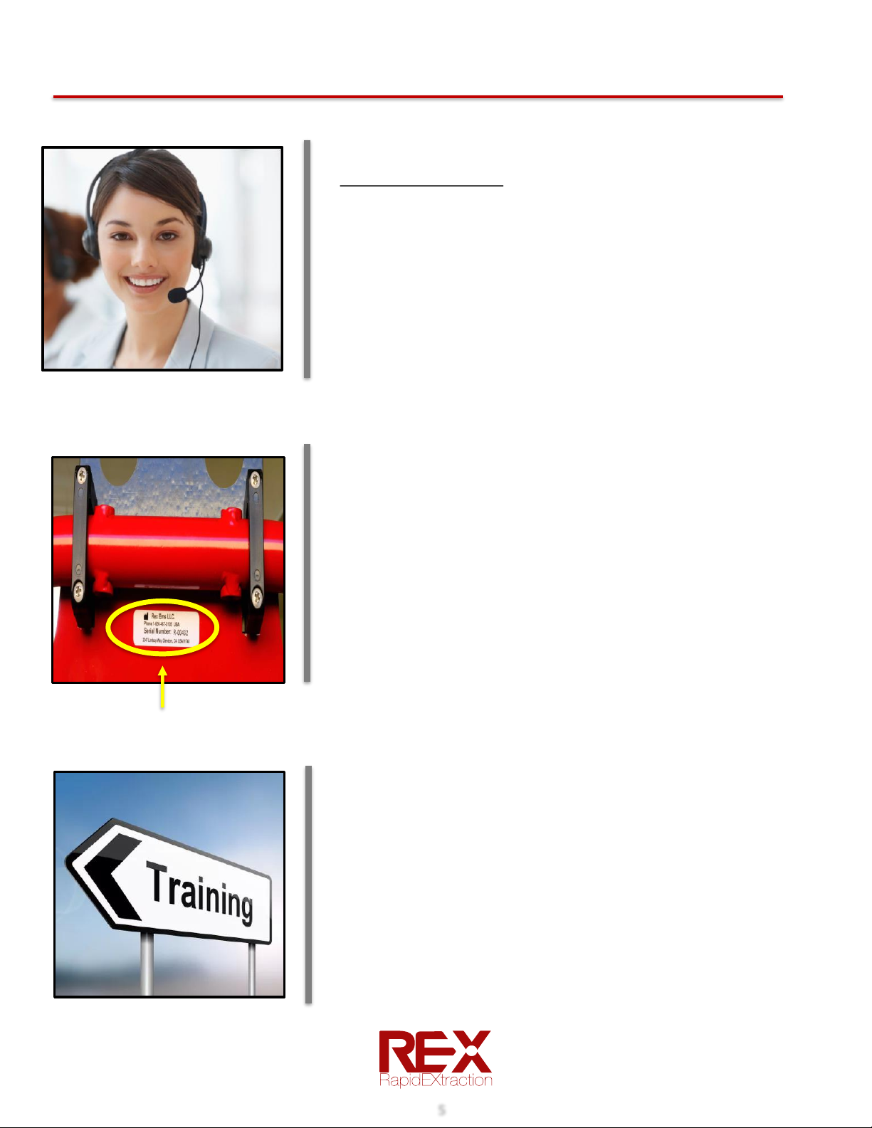
Rex EMS, LLC Service Department
2247 Lindsay Way, Glendora, CA 91740
(626) 467-3105
WARRANTY
Return Authorization
6

ICC Regulations require that claims for damaged products must be made within fifteen (15) days of receipt
of the product. Do not accept damaged shipments unless such damage is noted on the delivery receipt at
the time of receipt. Upon prompt notification, RexONE EMS will file a freight claim with the appropriate
carrier for damages incurred. Claims will be limited in amount to the actual replacement cost. In the event
that this information is not received by RexONE EMS within the fifteen (15) day period following the
delivery of the product, or the damage was not noted on the delivery receipt at the time of receipt, the
customer will be responsible for payment of the original invoice in full within thirty (30) days of receipt.
Claims for any incomplete shipments must be made within thirty (30) days of invoice.
This warranty reflects U.S. domestic policy. Warranty outside the U.S. may vary by country. Contact Rex
EMS, LLC for additional information.
International Warranty
Freight Damaged Product
7
WARRANTY

➢When RexONE DCS is used in dusty or sandy environment
•Spray RexONE DCS unit down with water
•Wipe dry or blow dry with compressed air
➢Scheduled Maintenance
Regular maintenance checks are recommended monthly
•Check panel release cables for wear and ease of use
•Check that Headrest engages in locking position
•Check brake system to ensure brake rod engages when handbrake squeezed
•Check all screws and bolts. Ensure they are secure and tight. Tighten as needed
•Lubricate the following using only a silicone-based lubricant. Wipe off excess
lubricant
oRed pull release ring at base of Pull Handle
oPush pin button on Pull Handle neck
oInsert wheel attachment points (holes) for Wheel Axles
oFrame hinge points (Head/Back, Center, and Foot Panels)
oRed release cords –Pull cords and apply lubricant on metal corner points
Preventative Maintenance
➢The RexONE DCS may be sprayed and wiped down with soap and water. Rinse soap
completely
➢If contaminated, use disinfectant solution and follow recommended decontamination
procedures
➢If debris gets between the frame joints or locking pins, the frame must be cleaned.
Compressed air may be used
➢Remove wheels prior to cleaning RexONE DCS unit
➢Spray and rinse the RexONE DCS unit. Clean front and backside of RexONE DCS unit.
➢Remove straps and spray with disinfectant or wash with soap and water.
➢If straps come in contact with bodily fluid or blood, disinfect straps with soap, commercial
solution, or wash in washing machine with commercial detergent.
➢Allow the straps to completely dry before reassembling.
➢Reassemble the straps and the wheels
➢Under HAZMAT situations, follow agency’s decontamination procedures
Cleaning & Disinfecting
MAINTENANCE & CLEANING
8

1. Remove the RexONE DCS from the carry case along with two wheels (Figures 1a, 1b)
2. Identify LEFT & RIGHT wheels from labels on fenders, set next to frame
3. Inspect for damage, missing parts, breaks, fractures in frame or hinges, bent or damaged components
4. DO NOT USE IF DAMAGE IS SUSPECTED OR FOUND
Figure 1a Figure 1b
ASSEMBLY INSTRUCTIONS
Unpacking & Inspection
9
Wheel Axle Port (Largest opening)
Figure 2a
1. Identify the Wheel Axle Port on Head/Center Panel hinge joint (Figure 2a)
2. Stand folded frame upright position. Do not lay frame on side with weight on brake rods (Figure 2b)
Wheel Installation
Figure 2b
Wheel Quick Release Button

3. Select LEFT or RIGHT wheel and match to proper side of Rex frame
4. Hold and depress Release Button in the center of the wheel
5. Locate Wheel Axel Port in the Head/Center Panel hinge (Figure 3b)
6. Align Wheel Axel with Wheel Port Axel and insert wheel
Wheel Installation, continued...
7. Repeat on other side
8. Confirm wheels are fully inserted and wheels can freely rotate
9. Open frame and secure Wheel Fenders by attaching colored Velcro straps to matching colored Velcro
attachments on each side of frame (Figures 2d, 2e)
Figure 2c
Attach Fender Velcro to Velcro area on frame
Repeat for other wheel
Figure 2d
ASSEMBLY INSTRUCTIONS
Inserting Axle into Wheel Axle Port
10
LEFT VELCRO Fender Tab
Figure 2e

1. Identify the RED Release Cable between the Foot Panel and Center Panel hinge area (Figure 4a)
2. Pull the Release Cable and extend the Foot Panel to the desired angle (Figure 4b)
3. Release pull cable lock panel into place
4. Gently move panel to ensure panel is locked in place. Foot Panel angles adjust to 0, (fully extended), 30, 60, and
90 (sitting) degrees.
Set Up Frame: Foot Panel
Figure 2a
Figure 4a
While pulling Release Cable extend foot panel
ASSEMBLY INSTRUCTIONS
Identify Foot Panel Release Cable
11
Set Up Frame: Head Panel
1. Tilt back folded frame flat so that the Head Panel is on top (Head Rest label is facing you)
2. Identify the RED Release Cable between the Head Panel and Center Panel hinge area (Figure 3a)
3. Pull the Release Cable and extend the Head Panel to the desired angle. Release pull cable to lock panel into place (Figure 3b)
4. Gently move panel to ensure panel is locked in place. Head Panel angles adjust to 0, (fully extended), 30, 60 and 90 (sitting)
degrees.
Figure 3a
Itentidy Red Release Cable While pulling Release Cable Extend Head Panel
Figure 3b

1. Identify the Red Release Ring at the base of the Pull Handle (Figure 4a)
2. Pull the Red Release Ring while rotating Pull Handle upward (Figure 4b)
3. Release Red Release Ring to lock Pull Handle into place
4. Pull Handle has Release Button on handle to extend or reduce length-press Button and pull or push handle
1. Locate the Foot and Head Plate Kickstands on the underside of the panels. Pull the Kickstand away from the
Foot Panel (Figure 5a) until it is fully open and locks into place
2. Repeat on Head Panel Kickstand if being used as a stretcher without wheel (Figure 5b)
While pulling Ring extend out Pull Handle
Figure 4a Figure 4b
Figure 5a Figure 5b
Pull Handle
Head and Foot Kickstands
Red Release Ring
ASSEMBLY INSTRUCTIONS
Extend out and lock Foot Kickstand Extend out and lock Head Kickstand
12

The system consists of adjustable chest, pelvic and leg strap
with Quick-Release buckle
All straps can be moved up or down based on patient needs
or injuries
1. Secure Check strap first. Position strap with buckle
across center of chest. Snap buckle and tighten (Figure
7)
2. Do not over tighten as this may interfere with
respirations
3. Repeat process for Pelvic strap
4. Use caution in patients with abdominal or pelvic injuries
5. Repeat process for Leg straps
6. Secure loose ends of straps
Figure 7
Release- Pull Down
Attaching Patient Strap
Headrest
1. Identify the Headrest. When stored in bag, headrest is
located on backside of the Head Panel
2. Pull Head rest downward to disengage lock from storage
position (Figure 6a)
3. Rotate Headrest upward until it aligns with the Head
Panel (Figure 6b)
4. Push Headrest in (towards the frame) to lock it into
position (Figure 6c)
Figure 6a
Figure 6b Figure 6c
Rotate Up Lock Push In
ASSEMBLY INSTRUCTIONS
13

1. Place RexONE DCS on its side or stand
the RexONE DCS unit upright with Pull
Handle upward
2. Pull and hold the Red Release Ring
(Figure 9a) at base of Pull Handle. Fold
Pull Handle down until it lays flat
against back of the Foot Panel (Figure
9b)
3. If using Telescoping Pull Handle, push
release button in and push Pull Handle
downward to shortest length. This will
prevent kickstand from jamming when
in closed position
Figure 9a Figure 9b
DISASSEMBLY INSTRUCTIONS
1. Pull Headrest upward until it releases (Figure 8a)
2. Rotate Headrest back towards frame (Figure 8b)
3. Lay Headrests flat against the back of the Head Panel
(Figure 8c)
Pull Handle
Headrest
Figure 8c
Figure 8b
Figure 8a
14

1. Release the Velcro tags holding the Wheel
Fenders to the Center Panel
2. Press Wheel Quick Release Button in the
center of wheel. At same time, pull the wheel
out from the Wheel Axle Post (Figure 10)
3. Turn RexONE DCS over and repeat for the
other wheel
1. Fold both kickstands underneath panels until
they lay flat. Shorten telescoping handle before
closing kickstands (Figure 11)
1. To release Foot Panel, pull and hold the Red
Release Cable at the Foot Panel
2. Fold the Foot Panel back and underneath the
Center Panel until lays flat (Figure 12)
3. Release Red Release Cable to lock the Foot
Panel in place
Figure 10
Quick Release Button
Figure 11
Figure 12
Foot Panel
Head and Foot Kickstands
Wheel Release
DISASSEMBLY INSTRUCTIONS
15

1. To release Head Panel, pull Red Release Cable at
base of Head Panel (Figure 13)
2. Fold the Head Panel forward on top off the
Center Panel until it lays flat on the Center Panel
3. Release Red Release Cable to lock the Head Panel
in place
1. Lay RexONE DCS Carry Bag on flat surface. Unzip carrycase and lay top panel open
2. Place the RexONE DCS frame into the carry case with Head Panel down (Figure 14a)
3. Tuck frame hinges deep within corner of the case to avoid wear on the bag
4. Place orange protection knob on brake rod (Figure 14b)
5. Place Protective Axle Sleeves on wheel axles to prevent scratching frame
6. Lay the wheels with axles downward. Place axles inside a panel vent. This will allow wheels to lay flat
(Figure 14c)
7. Zip the carry case closed
Figure 13
Figure 14a Figure 14b
Bag Placement
Head Panel
DISASSEMBLY INSTRUCTIONS
16
Axle Port
Figure 14c

The RexONE DCS is a multi-functional unit which can be used for an adult, adolescent, or child for the following
uses:
1. The RexONE DCS can be used as a backboard to stabilize and transfer a patient.
2. The RexONE DCS can transport patients on flat surfaces and uneven terrain
3. When extending the Head and Foot Kickstands and removing Quick-Release wheels, the RexONE DCS
becomes a patient treatment cot.
The RexONE DCS can support a maximum capacity of 400 lbs. during rest or on flat surfaces.
Prior to use always do a Safety Check
Make sure all connections are secured and locked into place
Ensure headrest is in locked position by pushing down into frame
Pull on hub of wheel to ensure locked and engaged
Check that Head Panel is securely engaged in locked position by moving panel back and forth
Move Foot Panel to secure in locked position
Move Pull Handle to ensure base connection is in locked position
Pull on Pull handle to ensure the telescoping pull handle is locked into position
Squeeze Hand Brake to ensure brake rods engage with wheels
INDICATIONS FOR USE
Deployment
17

1. Assess patient’s transport needs
2. Extend RexONE DCS frame to a prone or flat position
3. Ensure frame hinge points are in locked position (Will
hear “click” when hinge joints are moved into locked
position)
4. Align RexONE DCS frame with patient in backboard
position
5. Pull lower restraint strap out and away from RexONE
DCS frame
6. Use approved EMS guideline to move patient onto
RexONE DCS Backboard-stabilize patient neck and trunk
7. Roll patient on side and place RexONE DCS frame
against patient’s spine (Figure 15a)
8. With RexONE DCS supporting patient’s spine, roll patient
into a prone position (Figure 15b)
9. Once in prone (flat) position, secure patient with
strapping system (Figure 15c)
10. RexONE DCS can continued to be used as a back board
and carried by responders
Figure 15a
Figure 15b Figure 15c
RexONE DCS APPLICATIONS
Backboard Use
18
Table of contents