BEFORE STARTING — Rotate the external pump shaft by
hand to prime the pump. Start the pump motor and check for
oil flow thru the oil sight or in the oil troughs. If oil is not
circulating, reverse the motor shaft rotation and recheck.
Internal pumps on YBX units do not require priming, but check
for oil flow through the oil sight after the unit has been started.
RECHECK OIL LEVEL — After operating the unit for 2 or 3
minutes, shut down and immediately recheck the oil level
before oil lines drain. This reading will indicate the true
operating oil level. Add oil, if necessary, to raise level to the
“full” mark on the dipstick.
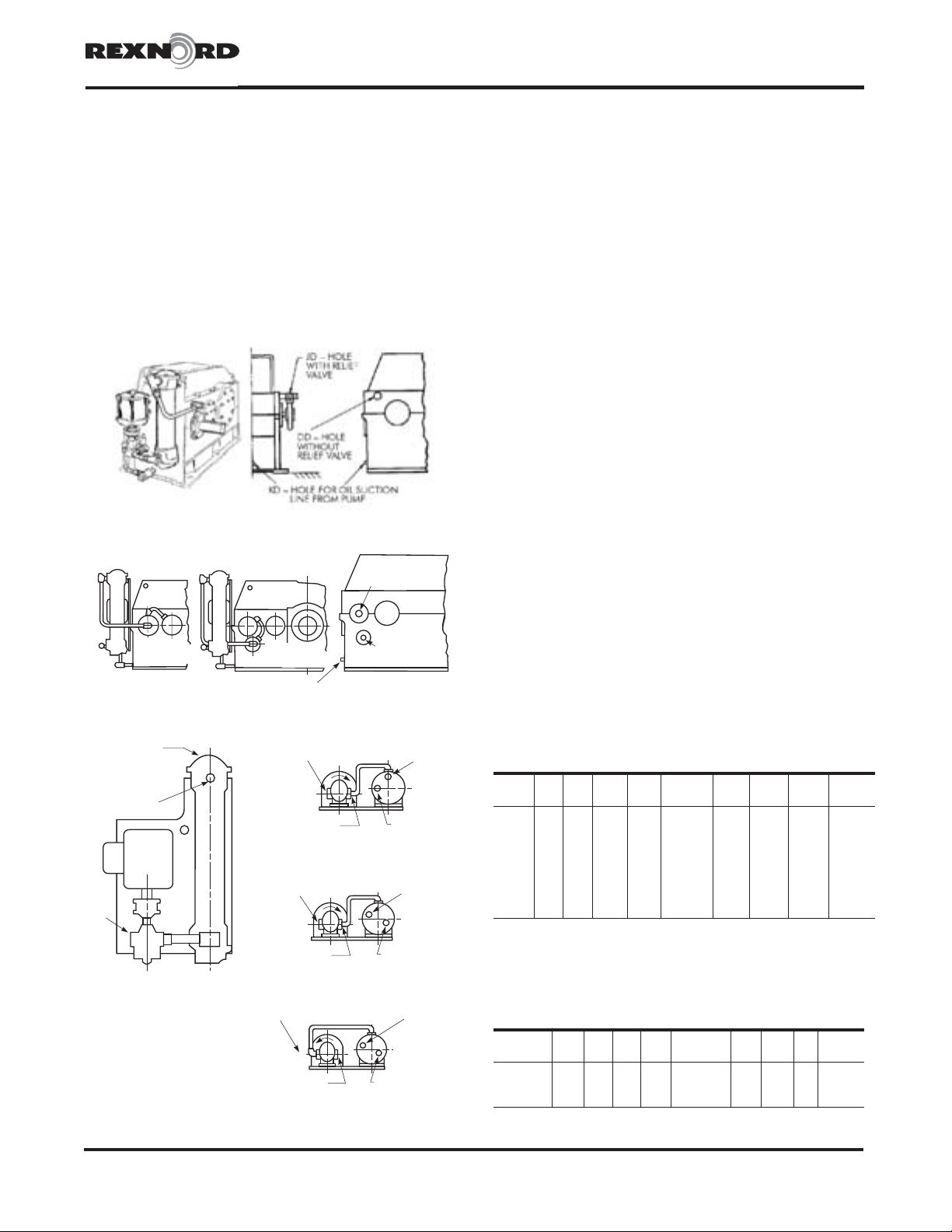
JET SPRAYS — Drives equipped with this system may be
identified by the oil piping shown in Figure 2. A jet of oil is
directed to the H.S. shaft bearings, while a spray of oil
lubricates the H.S pinion.
Check to see that an even spray of oil emerges from the nozzles
onto the pinion and that oil is flowing through the H.S bearings. If
not, disassemble the clogged portion and clean the oil passages
with a wire. Flush thoroughly to remove any contaminant.
Oil must be free of lint or any contamination that may clog the
lubrication nozzles or oil passages.
WATER FLOW — Be sure that all parts of the system are
clean and that the exchanger is full of fluid. Maintain the
specified rate of oil and water flow. Avoid excessive flow of
cooling water since this may cause tube failure through
erosion and may decrease cooling efficiency.
Add antifreeze per manufacturer’s specification to closed
water supply systems. However, note that antifreeze reduces
the rate of heat dissipation.
The additional thermal horsepower capacity provided by the
cooler is based on a 1:1 oil/water flow rate, a 55°F(31°C)
inlet temperature difference between oil and water,
90°F(32°C) inlet water temperature and maximum inlet water
pressure of 50 psig.
Adjust the water flow rate within the flow range shown on the
cooler or unit water circulation plate to maintain a reducer
operating temperature range of 140° to 160°F(60° to 71°C).
The minimum value of the range is for clean water at a
minimum velocity to prevent fouling of the tube bundle. For
brackish water, a flow rate of 2 times the minimum value is
required to prevent suspended solids from settling. The
maximum value of the range is based on a maximum velocity
to avoid erosion of the tube bundle.
MAINTENANCE
HEAT EXCHANGER — It is important that the inside parts are
kept clean. Inspect the exchanger periodically and clean
thoroughly. Inspect all tubes carefully for possible corrosion or
foreign material. Bleed the oil side of the cooler periodically if
air tends to collect in the system.
For open systems, drain vertical coolers by removing the two
zinc anodes and loosening the bottom bonnet. Disconnect and
drain the lines on horizontal open systems. Blow out all lines.
Heat exchangers are equipped with zinc anodes to minimize
galvanic corrosion. Inspect after first month of service and
periodically thereafter, depending on the severity of corrosion.
If 50% of the anode is used up, replace it.
Check the reducer oil level periodically. If it is ABOVE the
high level mark on the dipstick, have the oil analyzed for
water content. Moisture or water in the oil may indicate
that the heat exchanger is leaking. If so, replace the
exchanger immediately and change the oil.
EXTERNAL PUMP —Correct shaft alignment is essential;
check with a straightedge across the flanges of the coupling,
or use a feeler gauge between the faces of the coupling
halves at 90° intervals. The pump is a positive displacement
rotary type with a mechanical seal. Refer to manufacturer for
detailed maintenance.
INTERNAL PUMP — The lubricating pump on the 2000YBX2
exchanger cooled units is a positive displacement rotary type
manufactured at Falk. If maintenance is required, refer to the
Factory for detailed instructions.
OIL FILTER —If the filter is a Purolator, cleaning of the
element is accomplished by rotating the hand wheel several
turns once a week. Remove the filtering element and scrub
with a fiber bristle and a non caustic solvent at oil change
intervals. Flush out housing with solvent. If the filter is a
Marvel, follow the above element cleaning procedure, and
when reassembling, be sure that the “O” ring is properly
seated in the head groove.
JET LUBRICATION SYSTEM DISASSEMBLY —Disconnect
piping and remove the housing end covers. The oil manifold
with spray nozzles is attached to one end cover and will pull
free from the opposite cover. Refer to Figure 4.
JET LUBRICATION SYSTEM ASSEMBLY —Install all new
end cover gaskets. Align the nozzles in a horizontal plane
facing the centerline of H.S. pinion as shown in Figure 4.
MERCOID PRESSURE CONTROL SWITCH — The mercoid
switch is a sealed unit and should not be serviced. There is a
double adjustment for setting both “on” and “off” operating points.
RELIEF VALVE — This valve is pre-set at the factory and
normally does not require adjustment. However, rotating the
adjusting screw clockwise will reduce the opening pressure.
Accessories such as flow indicator, pressure gauges,
thermometers, heaters and pressure controls are sealed units.
If a malfunction occurs, return the sealed unit directly to the
manufacturer for repair or replacement.
Installation and Maintenance •Falk™ Gear Drive Type PC Pump and Cooler
(Page 2 of 3) All Sizes •Types Y, YF, YB, and YBX
Rexnord Industries, LLC, Gear Group148-931
3001 W. Canal St., Milwaukee, WI 53208-4200 USA Telephone: 414-342-3131December 1990