Service Instructions for No. 4 AC Solenoid Kit
Series 55,700 Disc Brakes
®
Brake Replacement Parts
P/N 8-078-945-05
effective 9/25/98
Important
Please read these instructions carefully
before servicing your Stearns brake.
Failure to comply with these instructions
could cause injury to personnel and/or
damage to property if the brake is
installed or operated incorrectly. For
definition of limited warranty/liability,
contact Rexnord Industries, Inc., Stearns
Division, 5150 S. International Dr., Cudahy
Wisconsin 53110, (414) 272-1100.
Caution
1. Installation or servicing shall be in
compliance with applicable local safety
codes including Occupational Safety
and Health Act (OSHA). All wiring and
electrical connections must comply with
the National Electric Code (NEC) and
local electric codes in effect.
2.To prevent an electrical hazard,
disconnect power source before
installing or servicing of the brake. If
power disconnect point is out of sight,
lock disconnect in the
off
position and
tag to prevent accidental application
of power.
3.The exterior surface of an operating
brake may be hot enough to cause
injury. Allow sufficient time for the brake
to cool before disassembly.
4. Do not operate brake with housing
removed. All moving parts should be
guarded.
5. After usage, the brake interior will
contain burnt and degraded friction
material dust.This dust must be
removed before servicing or adjusting
the brake.
DO NOT BLOW OFF DUST using an
air hose. It is important to avoid
dispersing dust into the air or inhaling
it, as this may be dangerous to your
health.
a) Wear a filtered mask or a respirator
while removing dust from the inside
of a brake.
b) Use a vacuum cleaner or a soft
brush to remove dust from the
brake.When brushing, avoid
causing the dust to become
airborne. Collect the dust in a
container, such as a bag, which can
be sealed off.
6. Installation or maintenance should be
performed only by qualified personnel
familiar with the construction and
operation of the brake.
7. For proper performance and operation,
only genuine Stearns parts should be
used for repairs and replacements.
Warning! Any mechanism or load held in
position by the brake should be secured
to prevent possible injury to personnel or
damage to equipment before any
disassembly of the brake is attempted or
before the manual release knob or lever is
operated on the brake.
Instructions
1. Remove housing (7) by unscrewing
nuts from the four mounting studs
(128) that protrude through the
reducer flange.
2. Grasp the coupler brake and motor as
a unit and pull free from the reducer.
3. Pull housing from the mounting studs
(128).These studs are threaded into
the C-face and should remain in place.
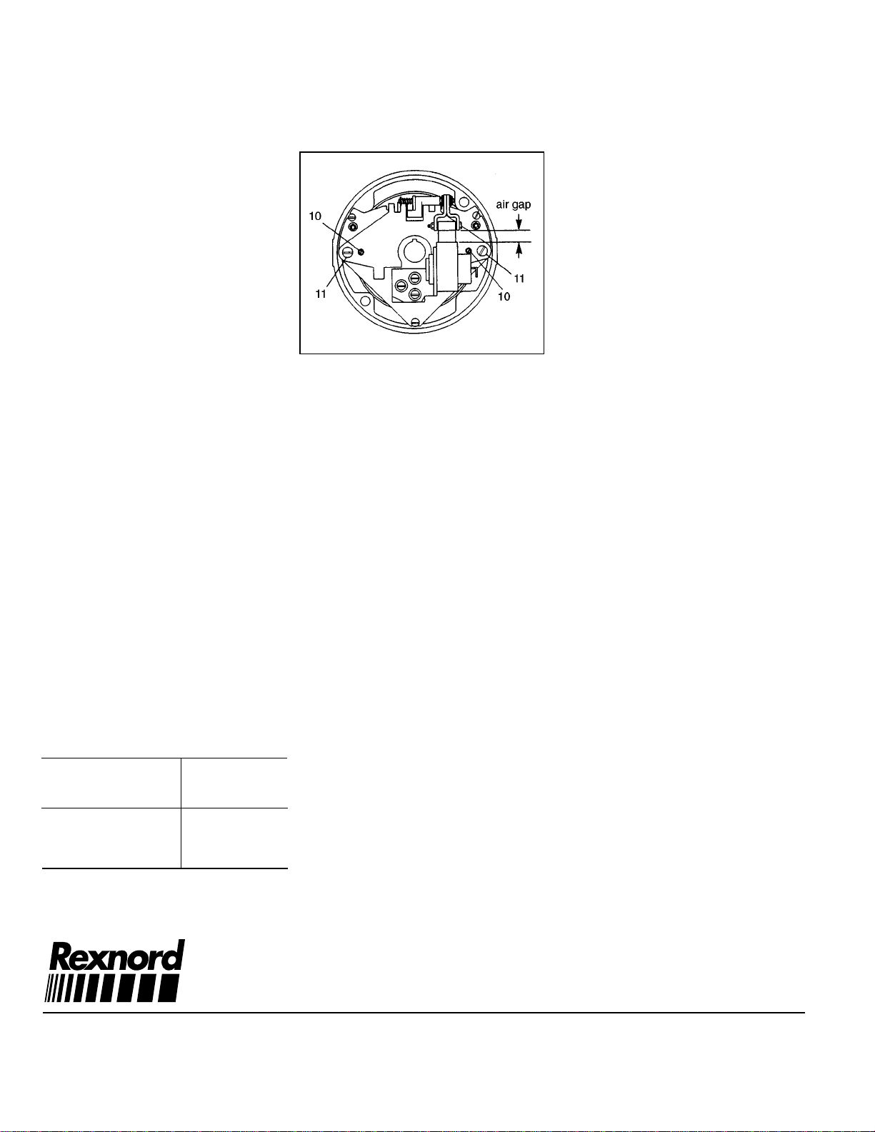
4. Solenoid replacement can be
accomplished without removing the
support plate from the brake.
5. Disconnect coil lead wires. Remove
three solenoid mounting screws (132)
to free solenoid frame (79). Note
mounting position.
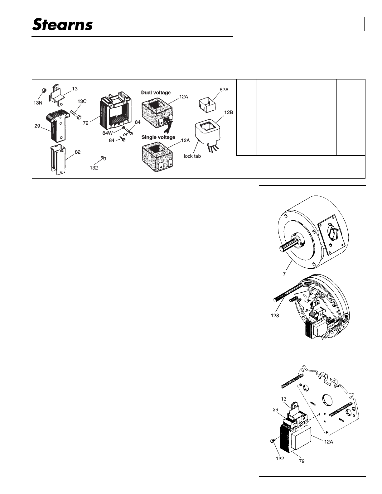
29
13
79
13C
13N
132
Solenoid plunger
Solenoid link
Solenoid frame
Solenoid link cap screw
Solenoid link nut
Solenoid mounting screw
1
1
1
1
1
3
Item
No. Description of Parts
Included in Kit Quantity.
per
Kit