3
1446
4142
44 1
SEE NOTE 7
MOUNTING ITEM 1 TO
SHEET METAL
(OPTIONAL)
1
41
42
44 43
CABLE CLIP ASSEMBLY
451617
SEE NOTES 3 & 4
10795892 MONITOR KIT
(OPTIONAL)
60
61 62 63
* ITEM NOT SHOWN IN ASSEMBLY VIEWS
NOTES:
FASTENER TORQUES PER DRAWINGS 436155 (INCH) AND 436156 (METRIC)
1.
EXCEPT WHERE NOTED.
USE LOCTITE PIPE JOINT COMPOUND #30557 (PART NUMBER 10164926)
2.
OR EQUIVALENT ON ALL NPT PIPE JOINTS.
CABLE TIES (ITEM 17) TO BE INSTALLED WHERE NEEDED. DRILL 0.144" (#27) PILOT HOLE.
3.
CABLE TIES (ITEM 17) AND VIBRATION SENSOR (ITEM 3) MAY BE EPOXY
4.
MOUNTED IF PREFERRED, USING EPOXY (ITEM 21).
SEE DRAWING 110023894 FOR WIRING DIAGRAM.
5.
USE LOCTITE #242 THREADLOCKER (PART NUMBER 10154332) OR EQUIVALENT
6.
ON FASTENERS PER FMS 6.610 AS INDICATED.
MODBUS CONVERTER (ITEM 1) CAN BE LOCATED AS NEEDED.
7.
DRILL & TAP M8x1.25 MOUNTING HOLE.
MOUNTING POSTS (ITEM 13) ONLY USED ON 190-220V UNIT SIZES.
8.
ONLY THESE TWO ORIENTATIONS
ARE ACCEPTABLE FOR VIBRATION
SENSOR.
SLAVE ID: 40
SEE NOTES 4 & 6
(LOCTITE MTG SCREWS)
A
A
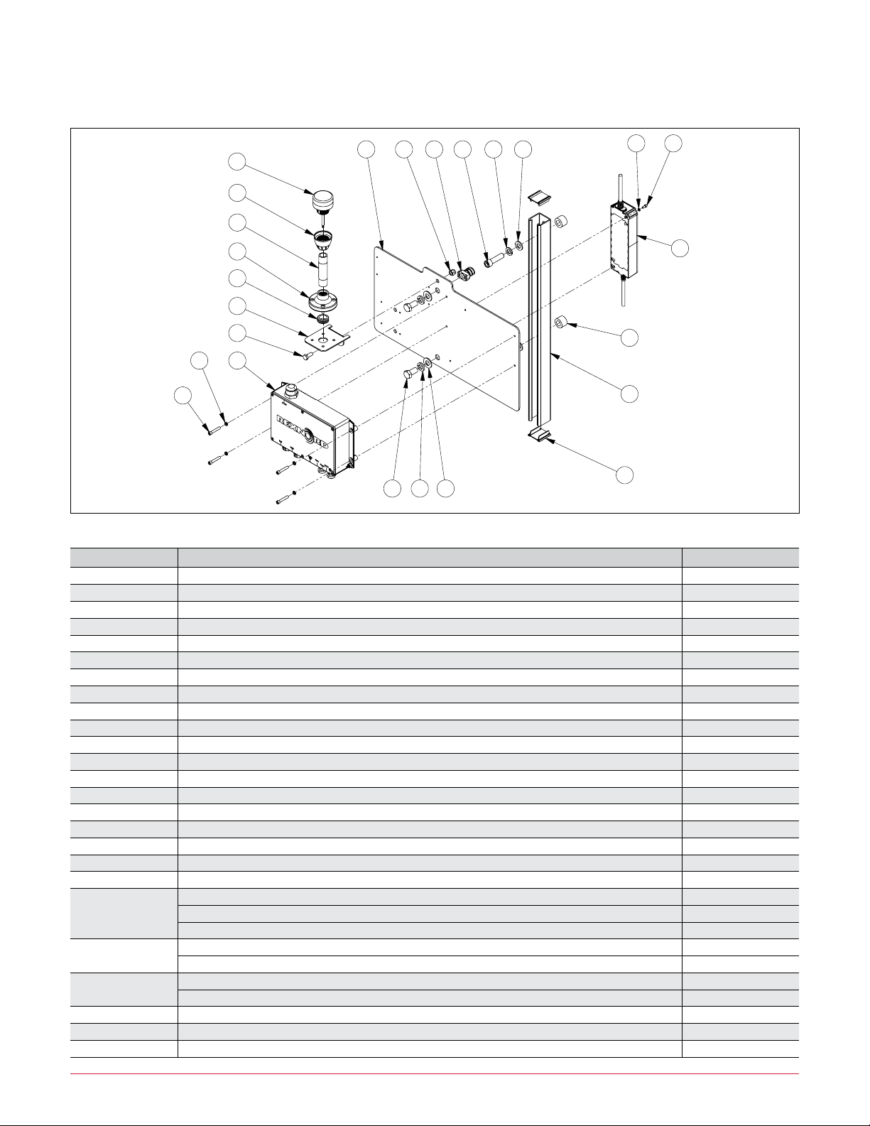
UNIVERSAL KIT BOM
ITEM
NO.
DESCRIPTION
QTY.
PART NO.
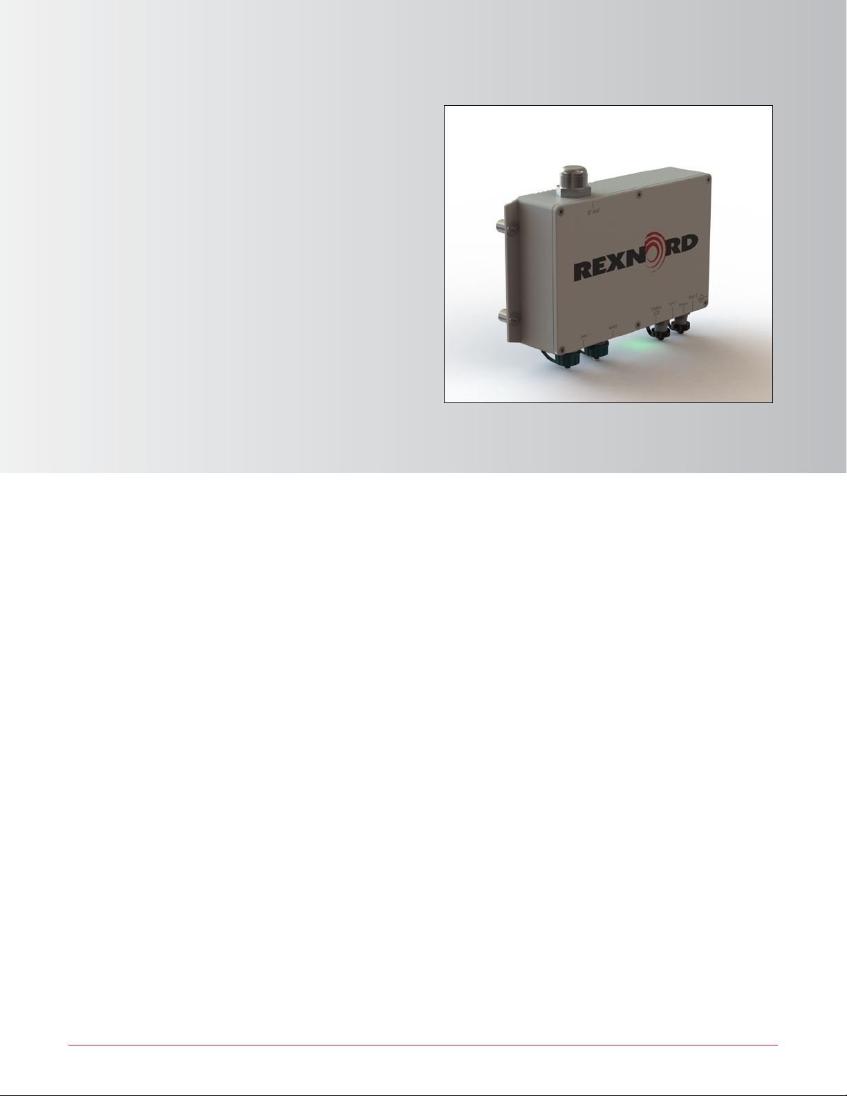
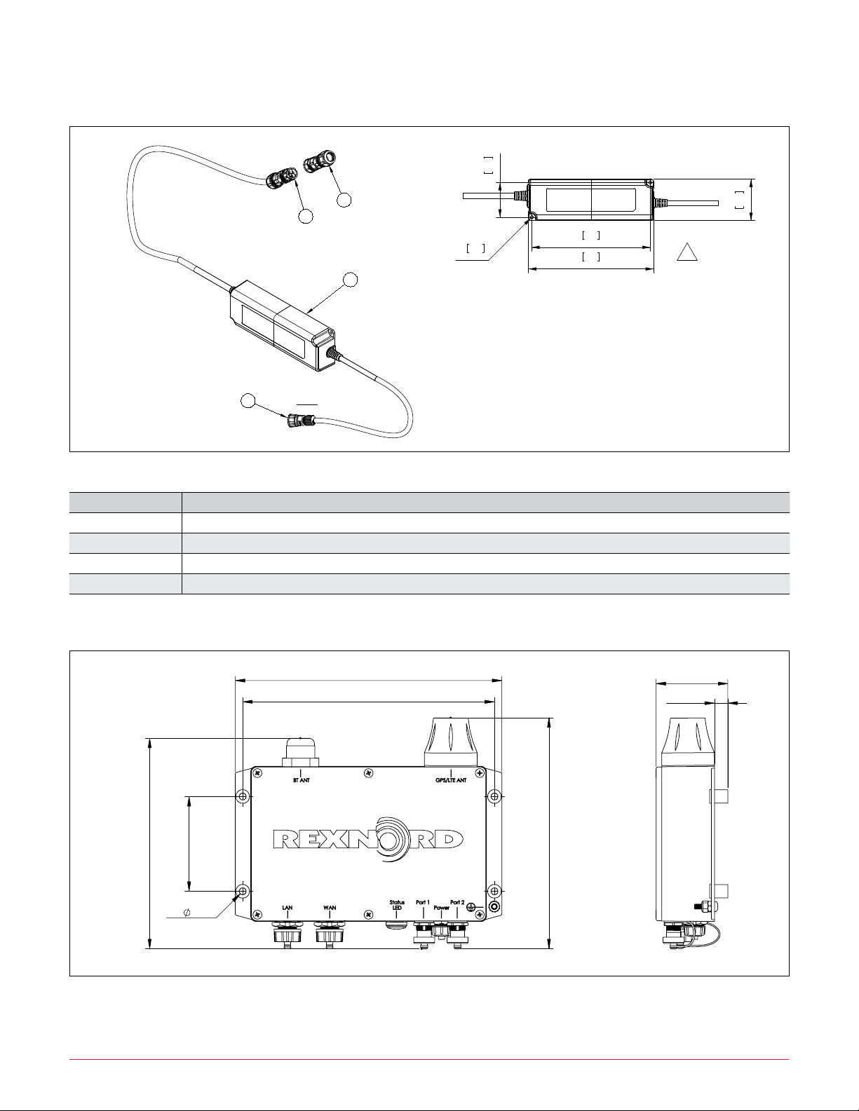
1
CONVERTER, MODBUS
1 10729698
2
ANDON LIGHT MODBUS MODIFIED
1 10674040
3
VIBRATION & TEMP SENSOR QM42VTQP MODIFD
1 10674039
4
EDGE-DEVICE, SERIAL, SED3 NO CELL
1 10782841
5
POWER-SUPPLY, PSU-SED503XYY KIT
1 10782845
6
CHANNEL 1-5/8"X1-5/8" SLOTTED, 32 IN, PRE-GALVANIZED
1 10791225
7
BRACKET SWITCH, ANDON LIGHT, 465A
1 10674013
8
BUSHING PUSH-IN RUBBER
1 10714028
9
BUSHING PIPE - PIPE MTG FLANGE
1 10609128
10
CONDUIT NIPPLE, ELECTRICAL 0.500-14 NPT X 3.50, GALVANIZED
1 10667340
11
ADAPTER PIPE - ANDON
1 10609126
12
MOUNTING PLATE, UNIVERSAL KIT, V3 EDGE DEVICE
1 10817916
13
MOUNTING POST, 190V-220V
2 10181094
14
RTD SUMP W/3-PIN CONNECTOR, 3.000"
1 10786580
15
END CAP FOR UNISTRUT, METAL, P1280EG
2 10606019
16
MOUNT, CABLE TIE, SS
8 10743680
17
CABLE TIE, HI-TEMP
8 10714805
18 *
SERIAL CABLE M12 F - M12 M, 5.0M, MOLDED
1 10738998
19 *
SERIAL CABLE M12 F - M12 M, 2.0M, MOLDED
2 10738996
20 *
SERIAL CABLE Y 2XM12 F TO M12 M, 0.25M
2 10739001
21 *
EPOXY, 2 PART DEVCON PLASTIC WELDER
1 10724955
22 *
LABEL QR CODE
1 10617071
23 *
BOX CARBON WALL 28X15X12
1 10804807
CONTENTS OF HARDWARE KIT 10818153
30
HEX HEAD CAPSCREW, 0.312-18UNC x 0.750", Gr.5, ZP
1 10063527
31
LOCKNUT, 0.312-18UNC, ZP
1 10064025
32
SOCKET HEAD CAPSCREW, #12-24UNC x 1.250", ZP
4 10812644
33
LOCKWASHER, #12, ZP
4 10812656
34
HEX HEAD CAPSCREW, 0.500-13UNC x 1.000", Gr.5, ZP
2 10063518
35
FLAT WASHER, 0.531 ID X 1.062 OD, 0.095 THK., ZP
2 10064172
36
LOCKWASHER, 0.500", ZP
2 10018201
37
CHANNEL NUT W/ SPRING, 1-5/8" SERIES, 0.500-13UNC
2 10605982
38
SOCKET HEAD CAPSCREW, M12x1.75 x 30, 8.8
2 10097296
SOCKET HEAD CAPSCREW, M12x1.75 x 45, 8.8
2 10097095
SOCKET HEAD CAPSCREW, 0.312-18UNC x 0.625"
2 10063413
39
FLAT WASHER, 13mm ID X 24mm OD X 2.5mm THK. (M12)
2 10093492
FLAT WASHER, 0.336 ID X 0.735 OD, 0.044 THK., 316SS
2 10219114
40
LOCKWASHER, M12, ZP
2 10084705
LOCKWASHER, 0.312", ZP
2 10064086
41
HEX HEAD CAPSCREW, M8x1.25 x 16, 8.8, ZP
1 10084648
42
LOCKWASHER, M8, ZP
1 10084708
43
HEX NUT, M8x1.25, ZP
1 10084703
44
HOSE CLAMP, Ø0,750", GALVANIZED
1 10741758
45
DRIVE SCREW ROUND HEAD, #8 X 0.375, ZP
8 10066024
46
PIPE BUSHING, 1.000-11.5 MP x 0.500-14 FP, ZP
1 10065334
PIPE BUSHING, 1.250-11.5 MP x 0.500-14 FP, ZP
1 10065336
PIPE BUSHING, 2.000-11.5 MP x 0.500-14 FP, ZP
1 10705867
47
SOCKET HEAD CAPSCREW, #8-32UNC X 0.375"
2 10063426
48
LOCKWASHER, #8, ZP
2 10064089
CONTENTS OF MONITOR KIT 10795892 (MONITOR KIT IS OPTIONAL)
60
MODBUS RTU MONITOR ASSY
1 10783609
61
SOCKET HEAD CAPSCREW, #10-24 x 0.750
4 10063433
62
FLAT WASHER, 0.219 ID X 0.500 OD, 0.049 THK.
4 10018205
63
LOCKWASHER, #10, ZP
4 10018202
64 *
SERIAL CABLE Y 2XM12 F TO M12 M, 0.5M
1 10739002
G
8
H
J
K
L
M
F
E
D
C
B
A
7
6
5
4
3
2
1
9
10
11
12
9
1
2
3
4
5
6
7
8
10
11
12
C
F
M
L
K
J
H
G
E
D
13
14
15
16
16
15
14
13
A
B
11-17-2020
.
.
KL
.
. .
A
THIS DOCUMENT CONTAINS CONFIDENTIAL/PROPRIETARY INFORMATION OF REXNORD INDUSTRIES, LLC.
NEITHER RECEIPT NOR POSSESSION THEREOF CONFERS ANY OWNERSHIP INTEREST IN RIGHT TO
REPRODUCE OR USE, OR DISCLOSE IN WHOLE OR IN PART, ANY SUCH INFORMATION WITHOUT
WRITTEN AUTHORIZATION FROM REXNORD INDUSTRIES, LLC. IT IS SUBJECT TO RETURN UPON DEMAND.
THESE COMMODITIES, TECHNOLOGY, OR SOFTWARE ARE SUBJECT TO THE UNITED STATES
EXPORT REGULATIONS. DIVERSION CONTRARY TO U.S. LAW AND OTHER RELEVANT EXPORT CONTROLS IS PROHIBITED.
SOLIDWORKS DRAWING
DO NOT CHANGE MANUALLY
DATE
CHKD
SYM
SCMS TIER 1010, V3
10-28-2020
D. JASKIE
N. ZASTROW
K. LEICK
ENGINEER
MFG./PUR.
DATE
DESIGNER
REV.
UNIT:
TITLE:
SIMILAR TO
SCALE
DWG. NO.
www.rexnord.com
REXNORD INDUSTRIES, LLC
110022851
1:4
110023960 Drawing
ASSY UNIVERSAL KIT
SIZE
A1
.
A
RESTRICTED
. .
..
FINISH MASS
ROUGH MASS
HEAT TREATMENT
MATERIAL
RGH. PART NO.
.
.
.
.
.
ASSY UNIVERSAL KIT
PART NAME
SHT. 1 OF 2
CLASSIFICATION=
.
SAP PART NO.
- UNLESS OTHERWISE SPECIFIED -
DIMENSIONS ARE IN MILLIMETERS
DIMENSIONS IN BRACKETS '[ ]'
ARE IN INCHES