RF Innovations RFI 150-W-D-DD-H-1 User manual

RFI 150-W-D-DD-H-1
radio modem
Operation
Manual
RF Innovations Pty Ltd
RF Communication Solutions

RFI 150-W-D-DD-H-1 radio modem
VHF Full-Duplex Data-Driven Split-Port Radio
Operation Manual
COPYRIGHT NOTICE
RF Innovations Pty Ltd reserves the right to make improvements on the product in this manual at any
time without notice.
No part of this manual may be produced, copied, translated, or transmitted in any form or by any means
without the written permission of RF Innovations Pty Ltd.
Information provided in this manual is intended to be accurate and reliable. However, RF Innovations Pty
Ltd assumes no responsibility for its use or infringements upon the rights of third parties that may result
from its use.
Reference No. MAN0065
Revision 1.7
May 2002

TABLE OF CONTENTS
CHAPTER 1
INTRODUCTION 1
CHAPTER 2
INSTALLATION 3
M
OUNTING
3
A
NTENNA
C
ONNECTION
4
A
UXILIARY
S
ERIAL
P
ORT
C
ONNECTION
4
M
AIN
S
ERIAL
P
ORT
C
ONNECTION
5
P
OWER
C
ABLE
C
ONNECTION
5
CHAPTER 3
CONFIGURATION 7
A
CCESSING THE
C
ONFIGURATION
M
ENU
7
R
ADIO
C
HARACTERISTICS
M
ENU
S
TRUCTURE
7
(C) C
HANNEL
C
ONTROL
M
ENU
8
(S) S
ET
C
URRENT
C
HANNEL
8
(A) A
SSIGN
F
REQUENCIES
8
(P) T
X
P
OWER
M
ENU
9
(R) RSSI T
RIGGER
L
EVEL
9
(F) R
ESTORE
F
ACTORY
D
EFAULTS
10
L
INK
M
ENU
S
TRUCTURE
10
(L) L
EAD
-I
N
B
YTE
C
OUNT
10
(P) F
RAME
P
REFILL
C
OUNT
10
(T) D
ATA
T
IMEOUT
11
S
ERIAL
P
ORT
C
ONFIGURATION
M
ENU
11
(B) B
AUD
R
ATE
M
ENU
12
(F) F
LOW
C
ONTROL
M
ENU
13
(N) N
O
P
ARITY
/ (E) E
VEN
P
ARITY
/ (O) O
DD
P
ARITY
13
(1) O
NE
S
TOP
B
IT
/ (2) T
WO
S
TOP
B
ITS
13
(7) S
EVEN
B
IT
D
ATA
/ (8) E
IGHT
B
IT
D
ATA
13
(D) S
ET TO
D
EFAULTS
13
(D) D
IAGNOSTICS
M
ENU
13
(S) D
ISPLAY
S
TATUS
14
(E) E
VENT
L
OG
M
ENU
14
(V) V
IEW
L
OG
15
(L) L
OG
L
EVEL
M
ENU
15
(T) T
EST
I
NDICATOR
LED 15
(L) S
HOW
S
TATS
/L
OGGING
15
(1) S
TATISTICS
M
ENU
16
(L) S
HOW
S
TATS
/L
OGGING
16
(2) D
ISPLAY
T
ASKS
16
CHAPTER 4
OPERATION 17
S
ERIAL
P
ORTS
17
D
IAGNOSTIC
M
ODES
17
LED I
NDICATORS
M
ODE
1 18
LED I
NDICATORS
M
ODE
2 18
LED I
NDICATORS
M
ODE
3 18
LED I
NDICATORS
M
ODE
4 19
LED I
NDICATORS
M
ODE
5 19
LED I
NDICATORS
M
ODE
6 (CFG) 19

APPENDIX A
TECHNICAL SPECIFICATIONS 21
APPENDIX B
FACTORY DEFAULTS 22
APPENDIX C
GLOSSARY 23
APPENDIX D
TROUBLESHOOTING 24
C
ARRIER
D
ETECT
LED
IS
R
ED
24
O
NLINE
LED
IS
R
ED
24
P
OWER
/ F
AULT
LED
IS
R
ED
24
APPENDIX E
CRESCENDO SERIES NAMING CONVENTIONS 26

RFI 150-W-D-DD-H-1 radio modem Operation Manual Chapter 1 Introduction
MAN0065 Rev 1.7 1
CHAPTER 1 INTRODUCTION
This manual is provided with the purchase of the Crescendo-series RFI-150 radio modem.
The Crescendo-series RFI-150 is a full-duplex data-driven split-port radio operating in the 148 – 174 MHz
VHF band. An air data rate of 19200 bps is achieved on 25 kHz channels with a 25kHz raster. It has a
maximum transmit power of 5W.
The manual is divided into the following sections:
Chapter 2: Installation;
Chapter 3: Configuration;
Chapter 4: Operation;
Appendix A: Technical Specifications;
Appendix B: Factory Defaults;
Appendix C: Glossary.
The Crescendo-series RFI-150 is shown in Figure 1.
Transmit RF Por
t
Heatsink
Mode Select Button
Power Connector
Standard
Mounting Hole
Auxiliary Serial
Connector Mounting Plate with
optional corner Shock
Absorbers (not shown)
LED Indicators
Quick-release
Mounting Hole
Main Serial
Connector
Aluminium Case
Label
Receive RF Port
Figure 1: The Crescendo-series RFI-150 radio

RFI 150-W-D-DD-H-1 radio modem Operation Manual Chapter 1 Introduction
MAN0065 Rev 1.7 2
The radio may be mounted horizontally or vertically. The normal mounting is with the RF connector
upward and the power/serial connectors downwards. Four mounting holes are provided for panel
mounting. The antenna connector is an RF 50 Ohm BNC.
Optional shock absorbers can be fixed between the Aluminium Case of the radio and Mounting Bracket.
This allows the radio to be used in rugged environments.

RFI 150-W-D-DD-H-1 radio modem Operation Manual Chapter 2 Installation
MAN0065 Rev 1.7 3
CHAPTER 2 INSTALLATION
Figure 1 shows the installation of a typical system using Crescendo-series RFI-150 radios. In this system
PC and PLC are each connected to their own radio.
Main
Aux
Main
Aux
RS-232RS-232 Base
Radio Mobile
Radio
PC PLC
Figure 2: Installation of Crescendo radios
Mounting
Each mechanical enclosure has several mounting options. The mounting may be tailored to the
application with:
Panel Mounting;
The radio is directly connected to the mounting bracket.
Vibration Resistant Mounting.
Shock absorbers separate the radio and mounting bracket, reducing the impact of vibration on the radio.
In each scenario, there is the option of:
Standard Mounting;
Requiring M6 or ¼ inch screws.
Quick Release.
Requiring M5 or
3
/
16
inch screws.
Refer to Figure 3 below for mounting dimensions.
As the Crescendo-series RFI-150 has been designed to operate with no forced cooling, it should be
placed in a well-ventilated location. Refer to specifications on environmental conditions.

RFI 150-W-D-DD-H-1 radio modem Operation Manual Chapter 2 Installation
MAN0065 Rev 1.7 4
Figure 3: Crescendo-series RFI-150 Mounting Dimensions
Antenna Connection
The antenna is connector is an RF 50 Ohm BNC (female), type BNC DAIALL R1/4/082. The antenna
cable should be a suitable low-loss 50 Ohm RF cable with a matching BNC connector (male).
Cable loss should be considered when evaluating the link margins.
Auxiliary Serial Port Connection
The “Aux” Serial Port provides an RS-232 female (DCE) interface for configuration and maintenance. The
RS-232 interface circuits are described in Table 1 below. The Aux serial port is not flow-controlled.
The DTE/DCE cable should be terminated with a matching DB-9 male connector.

RFI 150-W-D-DD-H-1 radio modem Operation Manual Chapter 2 Installation
MAN0065 Rev 1.7 5
Pin Number Circuit Description
1 n.c. -
2 RxD Receive Data
3 TxD Transmit Data
4 n.c. -
5 Ground -
6 n.c. -
7 n.c. -
8 n.c. -
9 n.c. -
Table 1: Auxiliary Serial Port RS-232 circuits (DCE convention)
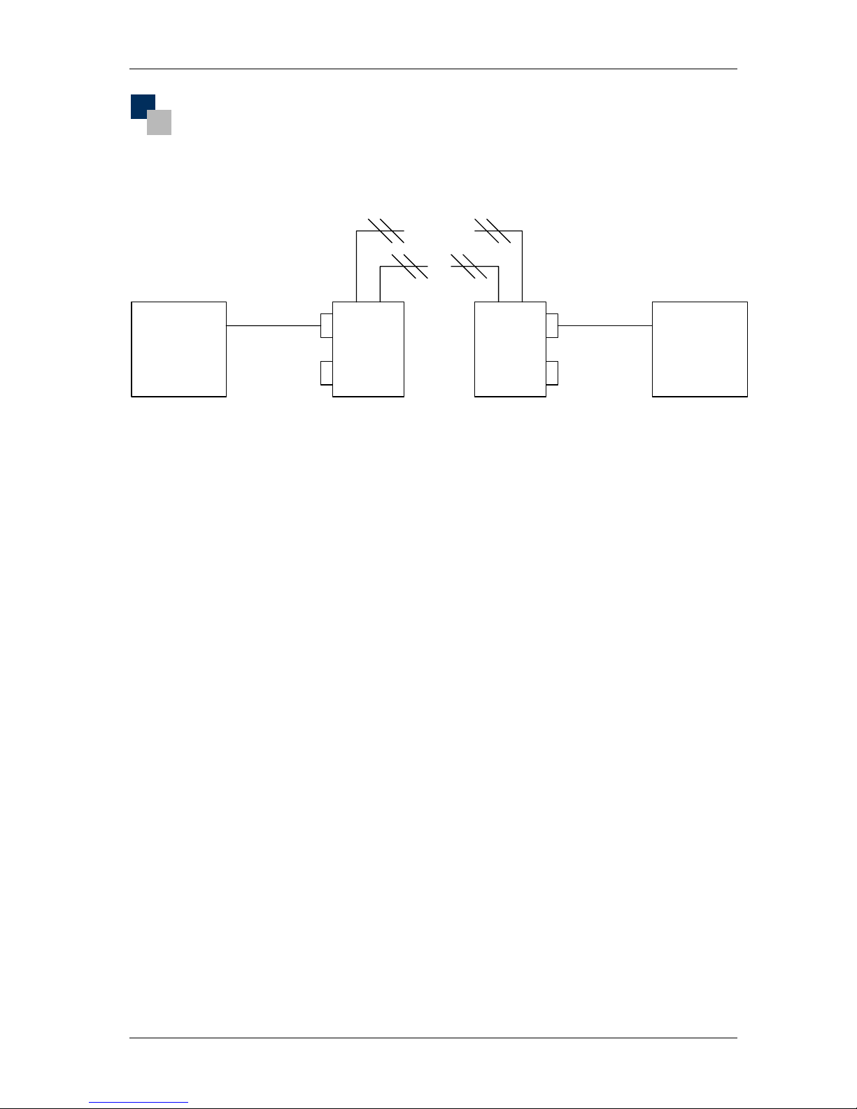
Main Serial Port Connection
The Main Serial Port provides an RS-232 female (DCE) interface. The RS-232 interface circuits are
described in Table 2 below. The main serial port is hardware flow-controlled.
The DTE/DCE cable should be terminated with a matching DB-9 male connector.
Pin Number Circuit Description
1 DCD Data Carrier Detect
2 RxD Receive Data
3 TxD Transmit Data
4 DTR Data Terminal Ready
5 Ground -
6 n.c. -
7 RTS Request to Send
8 CTS Clear to Send
9 n.c. -
Table 2: Main Serial Port RS-232 circuits (DCE convention)
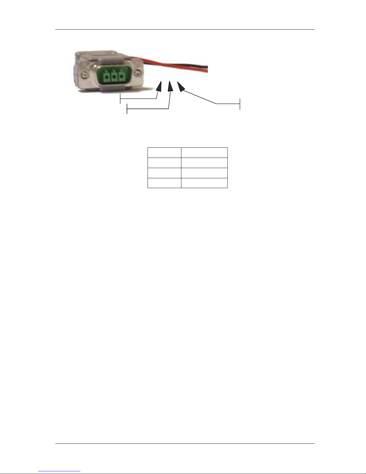
Power Cable Connection
The radio modem is powered via an external 12V dc power supply. The power supply connector is type
Phoenix Contact POWER-SUBCON PSC 1.5/3-M. A matching pair is supplied with the radio modem
(Phoenix Contact POWER-SUBCON PSC 1.5/3-F). Recommended cable size is (IEC) 0.14-1.5mm
2
(rigid
solid or flexible stranded), AWG 28-16.
Power connector pins refer to
Figure 4 and are described in Table 3.

RFI 150-W-D-DD-H-1 radio modem Operation Manual Chapter 2 Installation
MAN0065 Rev 1.7 6
Figure 4: Power Connector
Pin Connection
1 Common Ground
2 + 12 Volts
3 Common Ground
Table 3: Power Connector Pin Outs
Pin 1
Pin 2 Pin 3

RFI 150-W-D-DD-H-1 radio modem Operation Manual Chapter 3 Configuration
MAN0065 Rev 1.7 7
CHAPTER 3 CONFIGURATION
The Crescendo-series RFI-150 may be configured prior to operation using the internal configuration menu
system. Default system parameters are written in Italics as part of the description, factory defaults are
listed in Appendix B.
NOTE: If the value entered for a menu option is outside the specified range or is an invalid option, the
menu system shall ignore the entry and leave the parameter unchanged.
Accessing the Configuration Menu
The configuration menu is invoked by:
Connecting a terminal to the Auxiliary Port of the Crescendo-series RFI-150;
Setting the terminal emulator’s serial communication parameters to 19200, 8, N, 1;
Pressing and holding the push-button until the Power / Fault LED is lit, then releasing it.
When the button is released, the radio will send the configuration menu out the Auxiliary Port (refer to
Figure 5 below).
*** MiROS MAIN MENU (Version 2.0) ***
RFI-150 W-D-DD-H-1 Version 1.0 Rev.G
Serial No: Not Initialised
Manufactured Date: Not Initialised
(R) Radio Characteristics Menu
(L) Link Menu
(S) Serial Port Configuration Menu
(D) Diagnostics Menu
(Esc) To Exit Menu
Enter Choice: Figure 5: Crescendo-series RFI-150 internal menu
Navigation through the hierarchical menu system is controlled through the attached DTE. To exit a menu,
and go up a level, press the Escape key. Some menu options are implemented as soon as they are
selected; others require the menu to be exited first. 15 minutes without interaction will cause the menu
system to timeout.
Radio Characteristics Menu Structure
The Radio Characteristics Menu is selected by pressing ‘R’ at the Main Menu screen, shown in Figure 6.

RFI 150-W-D-DD-H-1 radio modem Operation Manual Chapter 3 Configuration
MAN0065 Rev 1.7 8
*** Radio Characteristics Menu ***
Current Channel: 0 Tx Freq = 157.40000 MHz Rx Freq = 174.77500 MHz
Tx Power Level = 27 dBm
RSSI trigger level = -110
(C) Channel Control Menu
(P) Tx Power Menu
(R) RSSI trigger level
(F) Restore Factory defaults
(Esc) Previous Menu
Enter Choice:
Figure 6: Radio Characteristics Menu
(C) Channel Control Menu
To change the channel control parameters, press ‘C’. The channel control menu provides access to
change the single Transmit (Tx) and Receive (Rx) frequencies for each channel.
*** Channel Control Menu ***
Current Channel: 0 Tx Freq = 157.40000 MHz Rx Freq = 174.77500 MHz
Channel: 0 Tx Freq = 157.40000 MHz Rx Freq = 174.77500 MHz
(S) Set Current Channel
(A) Assign frequencies
(Esc) Previous Menu
Enter Choice:
Figure 7: Channel Control Menu
(S) Set Current Channel
This option stops the radio hopping and sets it onto a specific channel. The radio then continues
to transmit and receive on that channel only. The default channel is 0. The following text is displayed
when this option is selected:
Enter channel : 0
(A) Assign Frequencies
This option allows the configuration of the Tx and Rx frequencies of the radio. The following text is
displayed when this option is selected:
Enter channel : 0
Enter Tx Freq: between 174.00000 MHz and 184.00000 MHz: 174.77500
Enter Rx Freq: between 157.00000 MHz and 167.00000 MHz: 157.40000

RFI 150-W-D-DD-H-1 radio modem Operation Manual Chapter 3 Configuration
MAN0065 Rev 1.7 9
(P) Tx Power Menu
By pressing ‘P’ in the Radio Characteristics Menu, the Tx Power Menu is accessed (Figure 8). The default
value is 27 dBm.
*** Tx Power Menu ***
Tx Power Level = 27 dBm
(0) 20 dBm
(1) 27 dBm
(2) 30 dBm
(3) 34 dBm
(4) 37 dBm
(5) OFF
(Esc) Previous Menu
Enter Choice:
Figure 8: Tx Power Menu
Tx Power in dBm (Decibels per Millivolt) to Watts approximate conversion.
20 dBm 0.1 watt (100 milliwatts)
27 dBm 0.5 watt (500 milliwatts)
30 dBm 1 watt
34 dBm 2.5 watts
37 dBm 5 watts
(R) RSSI Trigger Level
The RSSI Trigger Level is selected with the ‘R’ key. The Received Signal Strength Indicator (RSSI) trigger
sets the signal level required before the Crescendo-series RFI-150 will respond. RSSI is measured in
dBm (usually negative values). A value of –60dBm is a stronger signal than –80dBm.
The default value is –110 dBm. This value should be increased in noisy RF environments to prevent false
triggering.
When selecting this option, the following instruction is presented on the screen:
Enter RSSI trigger level as dBm (-140 to -40): -110

RFI 150-W-D-DD-H-1 radio modem Operation Manual Chapter 3 Configuration
MAN0065 Rev 1.7 10
Type the required value and press enter.
(F) Restore Factory Defaults
Sets the radio modem parameters to factory defaults values.
Link Menu Structure
The Link Menu contains the configuration information for the data transmission:
The Lead-In characters that precede a transmission;
The amount of time used to signal that the transmission has stopped.
The menu is shown in Figure 9. Configuration may be required for all the menu elements.
*** Link Control Menu ***
Lead-in Count = 0
Frame Prefill Count = 1
Data Timeout = 2
(B) Lead-in Byte count
(P) Frame Prefill Count
(T) Data Timeout
(Esc) Previous Menu
Enter Choice:
Figure 9: Link Menu
(L) Lead-In Byte Count
This parameter sets the number of lead-in bytes that will be discarded before the real data arrives. The
number of lead-in bytes used must be positive. The default value is 0. The following text is displayed:
Enter Lead-in Count (0-1000): 0
(P) Frame Prefill Count
The prefill count is the number of bytes that must be in the serial buffer before the radio will packetise the
data and transmit it. The number must be between 0 and 9 bytes, the default value is 0. The following text
is displayed:
Enter Prefill Count (0-9): 0

RFI 150-W-D-DD-H-1 radio modem Operation Manual Chapter 3 Configuration
MAN0065 Rev 1.7 11
(T) Data Timeout
The data timeout is the period of time without serial data. The radio uses this value to determine that the
data transmission has finished. The default value is 10. The following text is displayed:
Enter Data Timeout (0-3000) milliseconds: 10
Serial Port Configuration Menu
This menu allows the configuration for the serial port parameters for both the Main and Auxiliary ports.
The menu screen is shown in Figure 10.
*** Port Selection Menu ***
Main Port: 19200 Baud, No Parity, 8 Data, 1 Stop, No Flow
Main Port: Packet Timers: Output = Disabled, Input = Disabled
Aux Port: 19200 Baud, No Parity, 8 Data, 1 Stop, No Flow
Aux Port: Packet Timers: Output = Disabled, Input = Disabled
(M) Main Port
(A) Aux Port
(Esc) Previous Menu
Enter Choice:
Figure 10: Serial Port Configuration Menu
The Main Port may require configuration for compatibility with the existing machinery. Select ‘M’ to reveal
the menu shown in Figure 11. The options are explained below.

RFI 150-W-D-DD-H-1 radio modem Operation Manual Chapter 3 Configuration
MAN0065 Rev 1.7 12
*** Serial Port Configuration Menu ***
Main Port: 19200 Baud, No Parity, 8 Data, 1 Stop, No Flow
Main Port: Packet Timers: OutPut = Disabled, Input = Disabled
Main Port: Rx Buffer Limit = 256
(B) Baud Rate Menu
(F) Flow Control Menu
(N) No Parity
(E) Even Parity
(O) Odd Parity
(1) One Stop Bit
(2) Two Stop Bits
(7) Seven Bit Data
(8) Eight Bit Data
(A) Advanced Functions Menu
(D) Set to Defaults
(Esc) Previous Menu
Enter Choice:
Figure 11: Radio Configuration Menu
(B) Baud Rate Menu
The baud rate can be changed to several different speeds. The default baud rate is 19200. Refer to
Figure 12 below.
*** Baud Rate Menu ***
Main Port: Baud Rate = 19200
(0) 115200
(1) 57600
(2) 38400
(3) 19200
(4) 9600
(5) 4800
(6) 2400
(7) 1200
(8) 600
(9) 300
(A) 110
(Esc) Previous Menu
Enter Choice:
Figure 12: Baud Rate Menu

RFI 150-W-D-DD-H-1 radio modem Operation Manual Chapter 3 Configuration
MAN0065 Rev 1.7 13
(F) Flow Control Menu
This option allows selection of the type of flow control between the modem and DTE. The modem and
terminal must use the same type of flow control, specified in the Flow Control Menu in Figure 13.
Selection will return the system to Serial Port Configuration Menu, Figure 11. The default value is No Flow
Control.
*** Flow Control Menu ***
Main Port: No Flow
(H) Hardware Flow (RTS/CTS)
(S) Software Flow (XON/XOFF)
(N) No Flow
(Esc) Previous Menu
Enter Choice: Figure 13: Flow Control Menu
(N) No Parity / (E) Even Parity / (O) Odd Parity
These selections change the parity used for the serial connection. When a selection is made it is
displayed in the menu but not implemented until the menu is exited. The default value is No Parity.
(1) One Stop Bit / (2) Two Stop Bits
These selections change the number of stop bits used in the serial connection. When a selection is made
it is displayed in the menu but not implemented until the menu is exited. The default value is 1 Stop Bit.
(7) Seven Bit Data / (8) Eight Bit Data
These selections change the number of data bits used in the serial connection. The default value is 8 bit
data.
(D) Set to Defaults
This selection restores factory defaults for the selected serial port. Refer to Factory Defaults page 22 for
settings.
(D) Diagnostics Menu
The diagnostic Menu is used to test functions of the Radio Modems performance.

RFI 150-W-D-DD-H-1 radio modem Operation Manual Chapter 3 Configuration
MAN0065 Rev 1.7 14
*** Diagnostics Menu ***
(S) Display Status
(E) Event Log Menu
(T) Test Indicator LEDs
(L) Show Stats/Logging
(1) Statistics Menu
(2) Display Tasks
(Esc) Previous Menu
Enter Choice: Figure 14: Diagnostics Menu
(S) Display Status
This function gives a summary of the information regarding the configuration of the radio. A sample
screen is shown below in Figure 15. If a RSSI level cannot be determined “??” is displayed.
-------------------------- STATUS --------------------------
RFI-150 W-D-DD-H-1 Version 1.0 Rev.G
Serial No: Not Initialised
Manufactured Date: Not Initialised
Build Date: Jul 24 2002 Time: 12:19:00
Current Channel: 0 Tx Freq = 174.77500 MHz Rx Freq = 157.40000 MHz
Tx Power Level = 20 dBm
RSSI trigger level = -110 dBm
Menu Port = Aux Port
Last RSSI trip with data = ??
Average RSSI trip with data = ??
Average RSSI trip no data = ??
Average Noise = -122 dBm
Average Data Quality = 0
Average Frequency Error = 0.00 volts
CRC32 = C5270E42 of size 70548 bytes
CRC check Correct
Press Any Key to return Figure 15: Sample Status Screen
(E) Event Log Menu
The menu in Figure 16 is used by RF Innovations for general debugging information.
*** Event Log Menu ***
Log Level = Debug Information
(V) View Log
(L) Logging Level Menu
(C) Clear Log
(Esc) Previous Menu
Enter Choice: Figure 16: Event Log Menu

RFI 150-W-D-DD-H-1 radio modem Operation Manual Chapter 3 Configuration
MAN0065 Rev 1.7 15
(V) View Log
Used to actually view the debugging information supplied by the radio modem.
(L) Log Level Menu
Selected to change the type of information logged by the radio modem for display when the ‘V’ command
is selected. The default value is to collect Debug Information.
*** Logging Level Menu ***
Log Level = Debug Information
(0) Errors Only
(1) Warnings and Errors
(2) Status Information
(3) General Information
(4) Debug Information
(Esc) Previous Menu
Enter Choice: Figure 17: Logging Level Menu
(T) Test Indicator LED
Selecting this function starts a test of the front panel LEDs. This is a visual test and the LEDs must be
observed while in progress. The LEDs are turned on and off operating using all the colours in a
predefined sequence.
(L)Show Stats/Logging
This selection produces statistics and logged output, similar to that presented in Figure 18.
Total Packets Sent = 0 Total Packets Recvd = 0
Good packets = 0 Bad packets = 0
Empty Packets Sent = 0 Empty Packets Recvd = 0
Tx Triggers = 0 Carrier Detects = 0
Main Port:
Tx = 0 Rx = 0
Rx Errors = 0 Overflows = 0 Overruns = 0 Framing = 0
Tx Errors = 0 Overflows = 0
Aux Port:
Tx = 4600 Rx = 14
Rx Errors = 0 Overflows = 0 Overruns = 0 Framing = 0
Tx Errors = 0 Overflows = 0
Press Any Key to return
Figure 18: Sample Stats / Logging Screen

RFI 150-W-D-DD-H-1 radio modem Operation Manual Chapter 3 Configuration
MAN0065 Rev 1.7 16
110
Statistics Menu
The Statistics Menu may be used to view statistics as well as log information and to clear the log
databases.
*** Statistics Menu ***
(L) Show Stats/Logging
(P) Reset Physical Layer Logging
(S) Reset Serial Logging
(Esc) Previous Menu
Enter Choice: Figure 19: Statistics Menu
(L) Show Stats/Logging
Refer to (S) Show Stats/Logging and Figure 18, above.
(2) Display Tasks
The tasks are assigned to the radio controller when they are enabled. These tasks are performed at
predetermined times by the controller and do not affect the transfer of data. It is an indication of the
amount of work the controller is doing. Tasks are added or removed from the list as functions are enabled
or disabled by the user.
Idx Timer Handle Param Task Name
0 20 100 0 LED Refresh
1 10 101 0 Front Button
2 10 102 0 Front Panel
3 1 103 0 RFComm State Ctrl
4 10 104 1 Console
5 12 105 1 Main Menu
Press Any Key to return
Figure 20: Sample Display Tasks Screen
Table of contents
Other RF Innovations Radio Modem manuals