• Connect application to radio modem via ETH or SCC.
• Communication is indicated by LEDs (see manual).
• Before configuring the next radio delete table Art (Start, Run, arp -d) in the PC.
2. Connectors
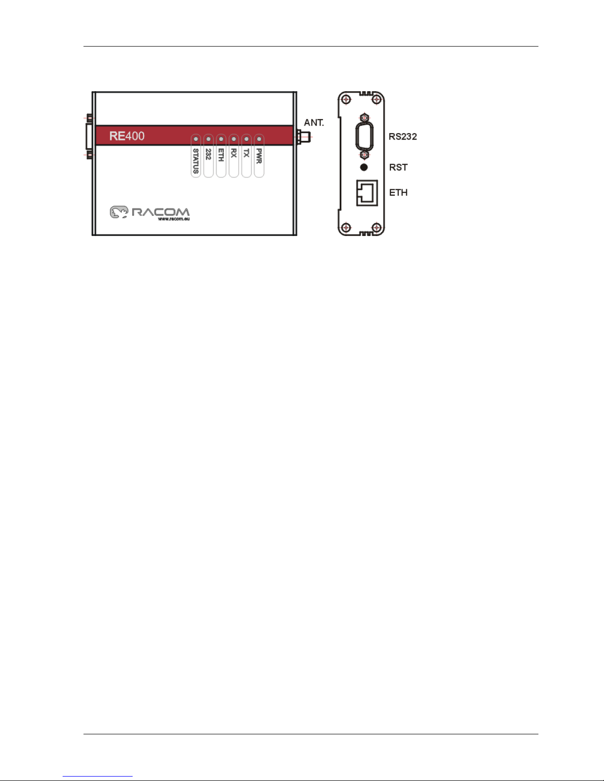
2.1. Antenna
Fig. 1: Antenna connector SMA
There is a SMA-jack antenna connector on panel of radio modem.
On your antenna cable use only respective type of connector of
respective impedance: SMA-plug, 50 Ω. It is recommended to use
antenna coaxial cables like this: RG58 up to 10 m, RG213 up to
25 m, H1000 for longer.
• Radio modem may be destroyed when antenna or dummy load
antenna is not connected!
2.2. Serial interface
Fig. 2: RS232, DSUB9 female
Tab. 1: RS232 - DSUB9F pins
signalpinsignalpin
DSR6CD1
RTS7RxD2
CTS8TxD3
+PWR9DTR4
GND5
2.3. Ethernet interface
Fig. 3: RJ-45F
• Ethernet connector RJ-45 for 10BaseT and 100BaseT meets fully
standard of Power over Etrhernet IEEE802.3af.
• Radio modem recognizes standard or cross cable and adapts itself
automatically.
2.4. Power suply - possibilities
• AUX – via RS232 DSUB9 connector, using pins 5 and 9 (see Tab.1).
Voltage 10,5–30 V, nominal 13,8 V.
• PoE – via Ethernet connector RJ-45 using PoE standard IEEE802.3af. Voltage 38–57 V. Common
version of supplying:
plus to pins 4+5
minus to pins 7+8
the polarity can be inverted also
Other options with PoE adapter see the standard IEEE802.3af.
• ! Only ONE from above power possibilities can be used !
Quick Start - RE400 – © RACOM s.r.o.2
Quick Start - RE400