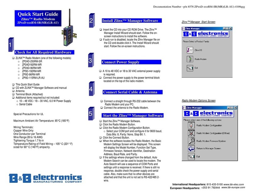
B&B Electronics Zlinx Xtreme ZXT9-RM User manual

Chipsmall Limited consists of a professional team with an average of over 10 year of expertise in the distribution
of electronic components. Based in Hongkong, we have already established firm and mutual-benefit business
relationships with customers from,Europe,America and south Asia,supplying obsolete and hard-to-find components
to meet their specific needs.
With the principle of “Quality Parts,Customers Priority,Honest Operation,and Considerate Service”,our business
mainly focus on the distribution of electronic components. Line cards we deal with include
Microchip,ALPS,ROHM,Xilinx,Pulse,ON,Everlight and Freescale. Main products comprise
IC,Modules,Potentiometer,IC Socket,Relay,Connector.Our parts cover such applications as commercial,industrial,
and automotives areas.
We are looking forward to setting up business relationship with you and hope to provide you with the best service
and solution. Let us make a better world for our industry!
Contact us
Tel: +86-755-8981 8866 Fax: +86-755-8427 6832
Email & Skype: [email protected]om Web: www.chipsmall.com
Address: A1208, Overseas Decoration Building, #122 Zhenhua RD., Futian, Shenzhen, China

Document Number: pnZXTxRM-0712m
Page 1
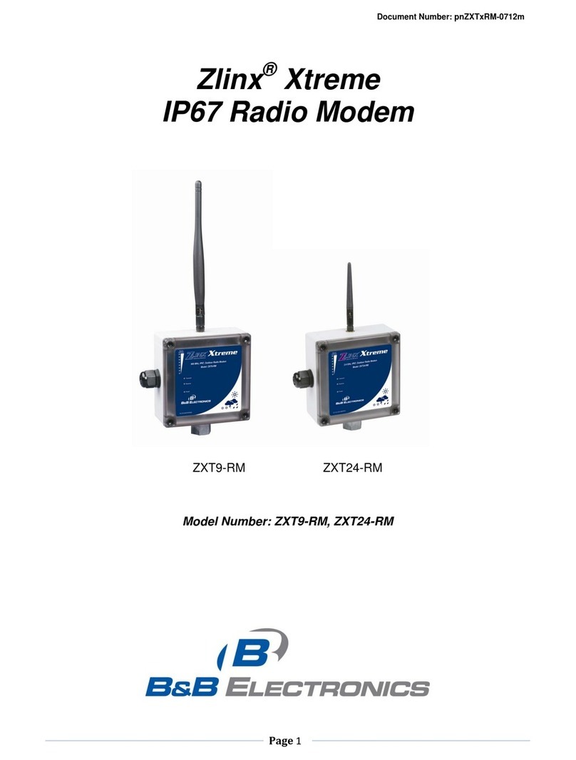
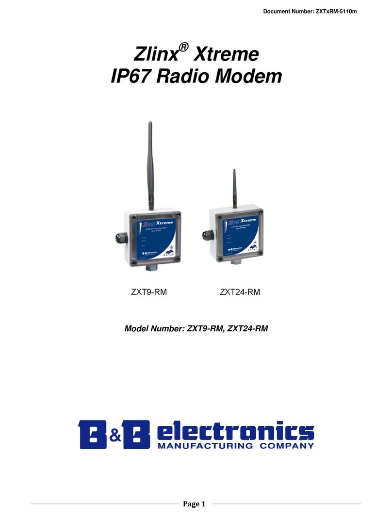
Zlinx®Xtreme
IP67 Radio Modem
ZXT9-RM ZXT24-RM
Model Number: ZXT9-RM, ZXT24-RM

Document Number: pnZXTxRM-0712m
Page 2
Zlinx Xtreme IP67 Radio Modem
ZXTx-RM Series
Documentation Number: ZXTx-RM-2310m
This product was designed and manufactured in Ottawa, Illinois USA
Using domestic and imported parts by
International Headquarters
B&B Electronics Mfg. Co. Inc.
707 Dayton Road
Ottawa, IL 61350 USA
Phone: (815) 433-5100 General Fax: (815) 433-5105
Website: www.bb-elec.com
European Headquarters
B&B Electronics
Westlink Commercial Park
Oranmore, Co. Galway, Ireland
Phone: (+353) 91-792444 Fax: (+353) 91-792445
Website: www.bb-europe.com
Revision –Original –June 2010
2010 B&B Electronics Mfg. Co. Inc. No part of this publication may be reproduced or transmitted in any form or by
any means, electronic or mechanical, including photography, recording, or any information storage and retrieval
system without written consent. Information in this manual is subject to change without notice, and does not
represent a commitment on the part of B&B Electronics Mfg. Co. Inc.
B&B Electronics Mfg. Co. Inc. shall not be liable for incidental or consequential damages resulting from the furnishing,
performance, or use of this manual.
All brand names used in this manual are the registered trademarks of their respective owners. The use of
trademarks or other designations in this publication is for reference purposes only and does not constitute an
endorsement by the trademark holder.

Document Number: pnZXTxRM-0712m
Page 3
Table of Contents
Contents
1.0 Overview.......................................................................................................................................... 6
1.1 PREREQUISITES ...........................................................................................................................................6
1.2 SAFETY INFORMATION .................................................................................................................................6
1.3 INSTALLATION INFORMATION .......................................................................................................................6
1.4 ABOUT THIS MANUAL ...................................................................................................................................6
1.5 PRODUCT FEATURES SUMMARY .................................................................................................................7
2.0 Product Information........................................................................................................................ 8
2.1 ZLINX®XTREME RADIO MODEM MODELS ...................................................................................................8
2.2 PACKAGE CONTENTS...................................................................................................................................8
2.3 MODES OF OPERATION................................................................................................................................8
2.3.1 Point-to-Point Serial ........................................................................................................... 8
2.3.2 Point-to-Point Serial to Xtreme I/O .................................................................................. 8
2.3.3 Point-to-Multi Point (Serial or Xtreme I/O) ...................................................................... 8
2.4 OPERATING STATES ....................................................................................................................................8
2.4.1 Idle State.............................................................................................................................. 9
2.4.2 Transmit State..................................................................................................................... 9
2.4.3 Receive State...................................................................................................................... 9
2.4.4 Sleep State.......................................................................................................................... 9
2.4.5 Command Mode ................................................................................................................. 9
2.5 USER INTERFACE COMPONENTS.................................................................................................................9
2.5.1 Signal Strength (RSSI) LED‟s .......................................................................................... 9
2.5.2 Transmit LED ...................................................................................................................... 9
2.5.3 Receive LED ....................................................................................................................... 9
2.5.4 Power LED ........................................................................................................................ 10
2.5.5 Internal User Interfaces ................................................................................................... 10
2.5.6 Push Button....................................................................................................................... 10
2.5.7 USB Connector................................................................................................................. 11
2.5.8 Terminal Block .................................................................................................................. 11
2.5.9 DIP Switch ......................................................................................................................... 12
3.0 Hardware Installation ................................................................................................................... 13
3.1 MECHANICAL DIAGRAM..............................................................................................................................13
3.2 IP67 CABLE GLAND INSTALLATION ...........................................................................................................13
3.2.1 CABLE GLAND DESCRIPTION .....................................................................................................................13
3.2.2 CABLE GLAND INSTALLATION ....................................................................................................................14
3.3 WATERTIGHT THREADED CONDUIT HUB ...................................................................................................14
3.3.1 DESCRIPTION .............................................................................................................................................14
3.3.2 WATER TIGHT THREADED CONDUIT INSTALLATION ..................................................................................15
3.4 IP67 MEMBRANE CABLE GLAND ...............................................................................................................15
3.4.1 DESCRIPTION .............................................................................................................................................15
3.4.2 IP67 MEMBRANE CABLE GLAND INSTALLATION .......................................................................................15
3.5 SUPPLIED ANTENNA...................................................................................................................................15
3.5.1 ZXT9-RM SUPPLIED ANTENNA.................................................................................................................15
3.5.2 ZXT24-RM SUPPLIED ANTENNA ..............................................................................................................16
3.6 OPTIONAL ANTENNAS ................................................................................................................................17
3.6.1 Omni Antenna Description .............................................................................................. 17
3.6.2 Yagi Antenna Description................................................................................................ 18
3.7 ANTENNA CABLES......................................................................................................................................20

Document Number: pnZXTxRM-0712m
Page 4
3.8 LIGHTENING ARRESTORS ..........................................................................................................................21
4.0 Electrical Installation .................................................................................................................... 22
4.1 WIRING .......................................................................................................................................................22
4.1.1 Terminal Block .................................................................................................................. 22
4.1.2 Power Supply Connections............................................................................................. 22
4.1.3 RS-232 Connections........................................................................................................ 23
4.1.3.1 RS-232 Signal Convention (DTE / DCE) .................................................................. 23
4.1.3.2 Wiring an RS-232 Device to the Radio Modem....................................................... 23
4.1.4 RS-485 Two Wire Connections...................................................................................... 24
4.1.5 RS-422/485 Four Wire Connections ............................................................................. 25
4.1.6 Termination and Biasing.................................................................................................. 25
4.1.7 Fault Output....................................................................................................................... 26
5.0 Software Installation..................................................................................................................... 28
5.1 ZLINX®MANAGER SOFTWARE OVERVIEW.................................................................................................28
5.1.1 Computer System Requirements................................................................................... 28
5.2 INSTALLING ZLINX®MANAGER SOFTWARE ...............................................................................................28
5.2.1 Installing Zlinx®Manager Software................................................................................ 28
5.2.2 Installing USB Drivers...................................................................................................... 32
5.3 STARTING ZLINX®MANAGER SOFTWARE..................................................................................................32
5.3.1 Starting the manager software ....................................................................................... 32
5.3.2 Radio Modem Configuration Screen ............................................................................. 33
5.3.2.1 Radio Modem Settings (ZXT9-RM) ........................................................................... 40
5.3.2.2 Radio Modem Settings (ZXT24-RM) ......................................................................... 50
5.3.3 Radio Modem Configuration Screen (Off-Line) ........................................................... 58
5.3.4 Radio Modem Firmware Update Screen ...................................................................... 58
5.3.5 Return to Manager ........................................................................................................... 59
5.3.6 Exit...................................................................................................................................... 59
6.0 Startup and Configuration ........................................................................................................... 60
6.1 BASIC SETTINGS ........................................................................................................................................60
6.1.1 CHANNEL NUMBER.....................................................................................................................................60
6.1.2 NETWORK IDENTIFIER ................................................................................................................................60
6.1.3 BAUD RATE,STOP BITS,PARITY,AND FLOW CONTROL ..........................................................................60
6.2 ADVANCED SETTINGS ................................................................................................................................60
6.3 RF MODEM OPERATION ............................................................................................................................61
6.3.1 TRANSPORT OPERATION ...........................................................................................................................61
6.3.2 SERIAL TO RF PACKETIZATION..................................................................................................................61
6.3.3 API OPERATION .........................................................................................................................................61
6.3.4 FLOW CONTROL.........................................................................................................................................62
6.3.5 SLEEP MODE..............................................................................................................................................63
6.3.5.1 PIN SLEEP MODE...................................................................................................................................63
6.3.5.2 SERIAL PORT SLEEP MODE ..................................................................................................................63
6.3.5.3 CYCLE SLEEP MODE .............................................................................................................................64
6.3.6 COMMAND MODE .......................................................................................................................................64
6.3.6.1 MODEM CONFIGURATION SWITCH ........................................................................................................65
6.3.6.2 AT COMMAND MODE.............................................................................................................................65
6.3.6.3 ENTERING AT COMMAND MODE ...........................................................................................................65
6.3.6.4 SENDING AT COMMANDS......................................................................................................................65
6.3.6.5 EXIT AT COMMAND MODE ....................................................................................................................65
6.3.6.6 BINARY COMMAND MODE .....................................................................................................................66
6.4 ZXT9-RM CONFIGURATION ......................................................................................................................67
6.4.1 ADVANCED PROGRAMMING .......................................................................................................................67
6.4.1.1 PROGRAMMING EXAMPLES USING AT COMMANDS...............................................................................67
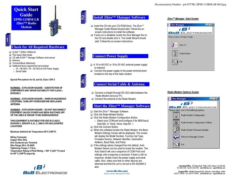
Document Number: pnZXTxRM-0712m
Page 5
6.4.1.2 PROGRAMMING USING BINARY COMMANDS ..........................................................................................67
6.4.2 COMMAND REFERENCE TABLE..................................................................................................................68
6.4.2.1 COMMAND DESCRIPTIONS.....................................................................................................................70
6.5 ZXT24-RM CONFIGURATION ....................................................................................................................91
6.5.1 ADVANCED PROGRAMMING .......................................................................................................................91
6.6 FIRMWARE UPDATE .................................................................................................................................140
6.6.1 CAUTION...................................................................................................................................................140
6.6.2 FIRMWARE UPDATE PROCEDURE .............................................................................................................140
7.0 Use Cases ................................................................................................................................... 142
7.1 POINT-TO-POINT SERIAL .........................................................................................................................142
7.1.1 USE CASE PARAMETERS .........................................................................................................................142
7.1.1.1 SETUP INSTRUCTIONS .........................................................................................................................142
7.2 POINT-TO-POINT SERIAL TO XTREME I/O ...............................................................................................147
7.2.1 USE CASE PARAMETERS .........................................................................................................................147
8.0 Testing and Trouble Shooting .................................................................................................. 148
8.1 RSSI RANGE TEST ..................................................................................................................................148
A. Appendix A –Specifications .........................................................................................................150
B. Appendix B –Default Configurations .......................................................................................... 153
B.1 Restore Default Configurations ................................................................................................ 153
B.2 ZKT9-RM Default Configuration............................................................................................... 153
B.3 ZKT24-RM Default Configuration ............................................................................................154
C. Appendix C –Dimensional Diagram / Mounting Instructions ..............................................156
C.1 DIMENSIONAL DIAGRAM...........................................................................................................................156
C.2 MOUNTING................................................................................................................................................157
C.3 SUPPLIED ANTENNA.................................................................................................................................158
D. Appendix D –Radio Frequency Basics .................................................................................. 160
D.1 WHAT IS DBM?.........................................................................................................................................160
D.2 Lower Frequencies = Better Propagation.......................................................................160
D.3 Range is not just a function of transmitter power .......................................................... 160
D.4 You must consider RF noise ............................................................................................ 161
D.5 Fade Margin is critical for reliable operation in adverse weather and interference.. 161
D.6 Remember Your Math ....................................................................................................... 162
D.7 RF Attenuation and Line of Sight .....................................................................................162
D.8 Path Loss Rule of Thumb..................................................................................................163
D.9 Antennas.............................................................................................................................. 163
D.10 Cable Loss.......................................................................................................................163
D.11 Latency and Packetization ............................................................................................ 164

Document Number: pnZXTxRM-0712m
Page 6
Section One –Overview
1.0 Overview
1.1 Prerequisites
This manual assumes you have a basic understanding of wireless communications, Serial Protocols
(RS-232/422/485), and basic electronics.
1.2 Safety Information
WARNING
Exposure to RF energy is an important safety consideration. The FCC has adopted a safety standard
for human exposure to radio frequency electromagnetic energy emitted by FCC regulated equipment
as a result of its actions in Docket 93-62 and OET Bulleting 65 Edition 97-01.
1.3 Installation Information
Operating Voltage
10 to 30 VDC
Maximum Surrounding Ambient Air Temp
74°C
Wiring Terminals
Use Copper Wire Only, One Conductor Per Terminal
Wire Range
30 to 12 AWG
Tightening Torque
0.5 to 0.6 Nm
Temperature Rating of Field Installed Conductors
105°C minimum, sized for 60°C ampacity.
Please see the Quick Start Guide for UL Class 1 Division 2 installation instructions.
DO NOT Operate unless all RF connectors are secure and any open connectors are
properly terminated
DO NOT Operate the equipment near electrical blasting caps or in an explosive
atmosphere.
All equipment must be properly grounded for safe operations. All equipment should be
serviced only by a qualified technician.
A separation distance of 20 cm or more should be maintained between the antenna of
this device and persons during device operation. To ensure compliance, operation at
closer than this distance is not recommended. The antenna used for this device must not
be co-located in conjunction with any other antenna or transmitter.

Document Number: pnZXTxRM-0712m
Page 7
1.4 About this Manual
This manual has been created to assist you in installing, configuring, operating, and trouble shooting
your Zlinx®Xtreme Radio Modem.
It is divided into eleven major sections.
Product Information –covers what is included with your radio modem, operating modes, operating
states, and user interface components.
Hardware Installation –covers how to install your radio modem. Additional information is provided
about RF considerations, accessory antennas, and cable selection.
Electrical Installation –covers wiring connections and powering your radio modem.
Software Installation –covers installing the manager software and basic software functionality.
Startup and Configuration –contains more detailed information about how to configure your radio
modem.
Use Cases –contains information concerning the most widely used configurations.
Testing and Troubleshooting –contains information about trouble shooting aids.
Appendix –has additional information.
1.5 Product Features Summary
Need to extend an RS-232/422/485 signal across a highway or across the building? Your Zlinx ®
Xtreme Radio Modem will do the job faster, easier, and less expensively than stringing cable. The
Zlinx ®Xtreme Radio Modem connects serial devices which can be set up in point to point or point to
multi point networks. Easy plug-and-play set-up saves installation and maintenance time. In addition,
Zlinx ® Xtreme Radio Modem meets the IP67 standard and is built to handle the heat, cold, and
environments of industrial operations.
Modbus compatible –no additional converters needed
RS-232, 422, 485 (2-Wire & 4-Wire) serial communications
Frequency range: ISM band, 902 to 928 MHz or 2.4 to 2.5 GHz
Signal strength indicators aids troubleshooting.
900 MHz or 2.4 GHz antenna included.
256 Bit AES Encryption
Wide, -40 to 74°C, Operating Temperature
Rugged Circuitry for Indoor and Outdoor Applications
IP67 Rated for total protection against dust and water up to 1 meter
Software support Windows XP, Vista, and 7 (32 / 64 Bit)
Field Upgradable Firmware

Document Number: pnZXTxRM-0712m
Page 8
Section Two –Product Information
2.0 Product Information
2.1 Zlinx®Xtreme Radio Modem Models
ZXT9-RM - 900 MHz ISM Band Radio Modem
ZXT24-RM –2.4 GHz ISM Band Radio Modem
2.2 Package Contents
Zlinx®Xtreme Radio Modem
Software CD
Quick Start Guide
Antenna
Enclosure Mounting Ears and hardware
NOTE: the Cable Glands cannot be used for Class 1 Division 2 applications.
Please see the Quick Start Guide for additional information about UL Class 1
Division 2 installation instructions.
2.3 Modes of Operation
2.3.1 Point-to-Point Serial
This configuration is used to wirelessly transmit serial data from one location to another. A
Zlinx®Xtreme Radio Modem is configured with another radio modem of same frequency in
a master slave relationship to transmit serial data wirelessly. Typical applications include
connecting a device such as a pressure/flow transmitter to a PLC or SCADA system.
2.3.2 Point-to-Point Serial to Xtreme I/O
This configuration is employed to connect a PLC/HMI/SCADA system to a remote Xtreme
I/O or Zlinx I/O module to monitor or control discrete devices via Modbus. The serial
master (PLC/HMI/SCADA) is a Modbus RTU master and must be connected to the serial
port of the Radio Modem. Each Xtreme I/O device populates and updates its own Modbus
map and support Modbus RTU Slave format. The radio modem is connected to the
respective Modbus Master. Typical examples include a Water tank monitoring system
where a float sensor level data is transmitted to a HMI through the wireless network.
2.3.3 Point-to-Multi Point (Serial or Xtreme I/O)
A Radio Modem is configured to communicate with multiple other modems or I/O
modules. The “master” modem is connected to the Modbus Master and can communicate
with Modbus Slaves connected to other radio modems or Xtreme I/O units. An example is
a PLC Process control/monitoring application requiring analog, digital and serial data to be
brought to a central PLC.
2.4 Operating States
The Zlinx®Radio Modem has six operating states.

Document Number: pnZXTxRM-0712m
Page 9
2.4.1 Idle State
•Checks for Valid RF Data received and discards invalid data
•Checks for serial data to be packaged and RF transmitted
•Received Valid RF data in buffer to be output serially
•Checks if Sleep Mode condition is met
•Checks for Command Mode commands
2.4.2 Transmit State
•Packages serial data (2048 bytes max in RF packet)
oZXT9RM –2048 bytes max
oZXT24RM –202 bytes max
•Returns to Idle State
2.4.3 Receive State
•Switches to Receive State to start receiving RF packets if RF data was detected while
in the Idle State
•Returns to Idle State when data is no longer detected or an error is detected
2.4.4 Sleep State
•This allows the radio modem to enter a state of low power consumption when not in
use.
2.4.5 Command Mode
Enters AT Command mode with +++ sent to serial input with Guard Time before and
after. Exits after Timeout. The guard times and the entry characters are user
configurable.
2.5 User Interface Components
2.5.1 Signal Strength (RSSI) LED’s
There are eight green LED‟s to indicate signal strength (Received Signal Strength
Indicator / “RSSI”). They are arranged to indicate RSSI from weakest (bottom LED lighted)
to strongest (all eight LED‟s lighted). See figure 2-1.
Figure 2-1 RSSI Indicator
2.5.2 Transmit LED
The green transmit LED flashes when data is transmitted out the serial port. See figure 2-
2 below.
2.5.3 Receive LED
The green receive LED flashes when data is received by the serial port. See figure 2-2
below.

Document Number: pnZXTxRM-0712m
Page
10
Figure 2-2 Transmit and Receive LED’s
2.5.4 Power LED
The green power LED is ON when power is applied.
Figure 2-3 Power LED
2.5.5 Internal User Interfaces
The remaining user interfaces are located inside the radio modem enclosure. To access
these interfaces, the cover must be removed. The cover is held in place with four plastic
Phillips style screws.
2.5.6 Push Button
Push Button PB1 is located on the circuit board behind the radio modem cover. It is used
to temporarily set the serial port to a know condition. To do this you must use the 232 port
on the modem. Press and hold the button while power cycling the device. Once power
comes up release the button and the unit will temporarily be restored to a know condition
and in command mode for about 20 seconds. You will then be able to connect to the
device using the manger at the settings listed below.
Baud rate = 9600
Data bit = 8

Document Number: pnZXTxRM-0712m
Page
11
Parity = None
Stop bit = 1
Figure 2-4 Push Button
2.5.7 USB Connector
The USB connector is located on the circuit board inside the radio modem enclosure. It is
used to connect a PC to the radio modem to perform configurations and firmware updates.
The connector is a type b female. Any commercially available USB cable can be used to
connect to the radio modem. Figure 2-5 shows the USB Connector location.
Figure 2-5 USB Connector
2.5.8 Terminal Block
The terminal block is used to connect serial signals and power. Figure 2-6 shows the
location.

Document Number: pnZXTxRM-0712m
Page
12
Figure 2-6 Terminal Block
2.5.9 DIP Switch
OFF
ON
Switch
RS-
232
RS-422
RS-485 4-
Wire
RS-485 2-
Wire
4 Wire
2 Wire
1
OFF
OFF
OFF
ON
4 Wire
2 Wire
2
OFF
OFF
OFF
ON
Termination Out
Termination In
3
OFF
OFF*
OFF*
OFF*
RS-422
RS-485
4
OFF
OFF
ON
ON
Note: The use of built in termination is optional and depends on your application
Note: For RS-232 operation, set all switches OFF
Figure 2-7 DIP Switch

Document Number: pnZXTxRM-0712m
Page
13
Section Three –Hardware Installation
3.0 Hardware Installation
3.1 Mechanical Diagram
The mechanical diagram in Appendix C contains information for mounting your radio modem.
NOTE: the Cable Glands cannot be used for Class 1 Division 2 applications. Please see
the Quick Start Guide for UL Class 1 Division 2 installation instructions.
3.2 IP67 Cable Gland Installation
3.2.1 Cable Gland Description
The Cable Gland is used to maintain the water tight rating while allowing a cable to enter
the enclosure. The assembly consists of black molded nylon body, hex nut, cable nut and
a rubber gasket and cable seal.
Figure 3-3 IP67 Cable Gland
Figure 3-4 IP67 Cable Gland

Document Number: pnZXTxRM-0712m
Page
14
3.2.2 Cable Gland Installation
1. The cable gland will accept cable diameters from 0.236 to 0.472 inches (5.99 to 11.99
mm).
2. Insert the Non-tapered end of the Body (D) through the conduit knock-out on the radio
modem enclosure.
3. Place the Gasket around the body on the outside of the enclosure.
4. Thread the Hex Nut onto the Body from the inside of the enclosure.
5. Place the Cable Nut onto the cable being careful to position the threaded side so that
it can be attached to the Cable Body.
6. Tighten the Cable Nut. This will cause the tapered end of the Cable Body to
compress, ensuring a water-tight seal.
3.3 Watertight Threaded Conduit Hub
Unused conduit openings: Class 1 Division 2 installation requires a UL
Recognized conduit plug (UL Category Code QCRV2) be used when a conduit
opening is not being used.
3.3.1 Description
Another method to bring a cable into the enclosure is to use the water tight threaded
conduit hub. It is used to secure threaded half inch rigid service entrance conduit. It
consists of a Body, Nut, and Gasket.
Figure 3-5 ½ Inch Threaded Conduit Hub
Figure 3-6 ½ Inch Threaded Conduit Hub

Document Number: pnZXTxRM-0712m
Page
15
3.3.2 Water Tight Threaded Conduit Installation
1. Insert the treaded end of the body into the conduit knock-out from the outside of the
enclosure. The rubber gasket should be on the outside of the enclosure.
2. Thread the Nut onto the conduit body from inside the enclosure.
3. 1/2 and 3/8 inch conduit fittings as well as 1/2 Inch, rigid, threaded conduit can be
attached to the threaded hub.
3.4 IP67 Membrane Cable Gland
NOTE: the Cable Glands cannot be used for Class 1 Division 2 applications. Please see
the Quick Start Guide for UL Class 1 Division 2 installation instructions.
3.4.1 Description
The membrane cable gland is used to plug an unused hole in the enclosure.
Figure 3-7 IP67 Membrane Cable Gland
3.4.2 IP67 Membrane Cable Gland Installation
1. Stuff the cable gland into the knock-out hole with the narrow end toward the inside of
the radio modem enclosure. The enclosure wall will fit into the indentation between
the inside and outside portions of the gland.
3.5 Supplied Antenna
3.5.1 ZXT9-RM Supplied Antenna
Your Zlinx Xtreme 900 MHz product comes supplied with a “rubber duck” style antenna
which can be articulated up to 90 degrees. Then antenna is a ¼ wave dipole with an omni
directional pattern and vertical polarization. It is recommended that your Zlinx Xtreme
product be mounted vertically.

Document Number: pnZXTxRM-0712m
Page
16
Figure 3-8 ZXT9-RM Supplied Antenna
Impedance
50Ω
Connector
RPSMA Female
VSWR
2.0 Max (in-band)
Gain
3.0 dBi
Polarization
Vertical
Replacement Part Number
ZXT9-ANT1
3.5.2 ZXT24-RM Supplied Antenna
Your Zlinx Xtreme 2.4 GHz product comes supplied with a “rubber duck” style antenna
which can be articulated up to 90 degrees. Then antenna is a ¼ wave dipole with an omni
directional pattern and vertical polarization.
It is recommended that your Zlinx Xtreme product be mounted with the antenna on the
top, perpendicular with the horizon
Figure 3-9 ZXT24-RM Supplied Antenna
Impedance
50Ω
Connector
RPSMA Female
VSWR
2.0 Max (in-band)
Gain
2.1 dBi
Polarization
Vertical
Replacement Part Number
ZZ24D-ANT1

Document Number: pnZXTxRM-0712m
Page
17
3.6 Optional Antennas
3.6.1 Omni Antenna Description
In some applications, a higher gain Omni directional antenna may be required. An Omni-
directional antenna is an antenna system which radiates power uniformly in one plane with
a directive pattern shape in a perpendicular plane. This pattern is often described as
"donut shaped". Omni-directional antenna can be used to link multiple directional
antennas in outdoor point-to-multipoint communication.
Omni Directional antennas are a good choice if you need to mount your antenna on a
mast to increase its elevation. Please note that mounting brackets must also be
purchased. Also note that these antennas have an N style connector. Refer to section 3.9
to select the correct cable.
Figure 3-10 Representative Photograph of Optional Omni Antenna
FG9023 –High Gain Omni Directional (900 MHz)
Use With
ZXT9-RM (900 MHz)
Impedance
50Ω
Connector
N Female
VSWR
2:1 Max (In Band)
Gain
3 dBi
Polarization
Vertical
Length
25 inches (63.5 cm)
Mounting Brackets (Not Included)
FM2

Document Number: pnZXTxRM-0712m
Page
18
FG9026 –High Gain Omni Directional (900 MHz)
Use With
ZXT9-RM (900 MHz)
Impedance
50Ω
Connector
N Female
VSWR
2:1 Max (In Band)
Gain
6 dBi
Polarization
Vertical
Length
65 inches (165.1 cm)
Mounting Brackets (Not Included)
FM2
FG24008 –High Gain Omni Directional (2.4 GHz)
Use With
ZXT24-RM (2.4 GHz)
Impedance
50Ω
Connector
N Female
VSWR
1.5:1 Max (In Band)
Gain
8 dBi
Polarization
Vertical
Length
24.5 inches (62.2 cm)
Mounting Brackets (Not Included)
FM2
3.6.2 Yagi Antenna Description
A Yagi-Uda Antenna, commonly known simply as a Yagi antenna or Yagi, is a directional
antenna system consisting of an array of a dipole and additional closely coupled parasitic
elements (usually a reflector and one or more directors). The dipole in the array is driven,
and another element, typically 5% longer, effectively operates as a reflector. Other
parasitic elements shorter than the dipole may be added in front of the dipole and are
referred to as directors. This arrangement increases antenna directionality and gain in the
preferred direction over a single dipole.
Since Yagi Antennas are directional, they must point directly at the other antenna
through a clear line of sight.
Figure 3-11 Enclosed Yagi –Model YE240015 for 2.4 GHz Models

Document Number: pnZXTxRM-0712m
Page
19
Figure 3-12 Representative Yagi Antenna Photograph
YS8963 –High Gain Yagi (900 MHz)
Use With
ZXT9-RM (900 MHz)
Impedance
50Ω
Connector
N Female
VSWR
1.5:1 Max (In Band)
Gain
6 dBi
Polarization
Vertical
Length
16.8 inches (42.7 cm)
Mounting Brackets
Included
YS8966 –High Gain Yagi (900 MHz)
Use With
ZXT9-RM (900 MHz)
Impedance
50Ω
Connector
N Female
VSWR
1.5:1 Max (In Band)
Gain
9 dBi
Polarization
Vertical
Length
27.8 inches (70.6 cm)
Mounting Brackets
Included
YS89612 –High Gain Yagi (900 MHz)
Use With
ZXT9-RM (900 MHz)
Impedance
50Ω
Connector
N Female
VSWR
1.5:1 Max (In Band)
Gain
11 dBi
Polarization
Vertical
Length
49 inches (124.5cm)
Mounting Brackets
Included
Other manuals for Zlinx Xtreme ZXT9-RM
2
This manual suits for next models
3
Table of contents
Other B&B Electronics Radio Modem manuals

B&B Electronics
B&B Electronics Zlinx ZP Series User manual

B&B Electronics
B&B Electronics ZP8 Series User manual

B&B Electronics
B&B Electronics Zlinx ZP Series User manual

B&B Electronics
B&B Electronics Zlinx ZP Series User manual

B&B Electronics
B&B Electronics ZP9D-115RM-LR User manual

B&B Electronics
B&B Electronics Zlinx Xtreme ZXT9-RM User manual

B&B Electronics
B&B Electronics Zlinx ZP24D-250RM-SR User manual

B&B Electronics
B&B Electronics Zlinx ZP24D-250RM-SR User manual

B&B Electronics
B&B Electronics ZP9D-115RM-LR User manual

B&B Electronics
B&B Electronics Zlinx Xtreme IP67 ZXT9-RM User manual