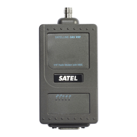
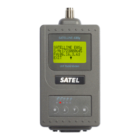
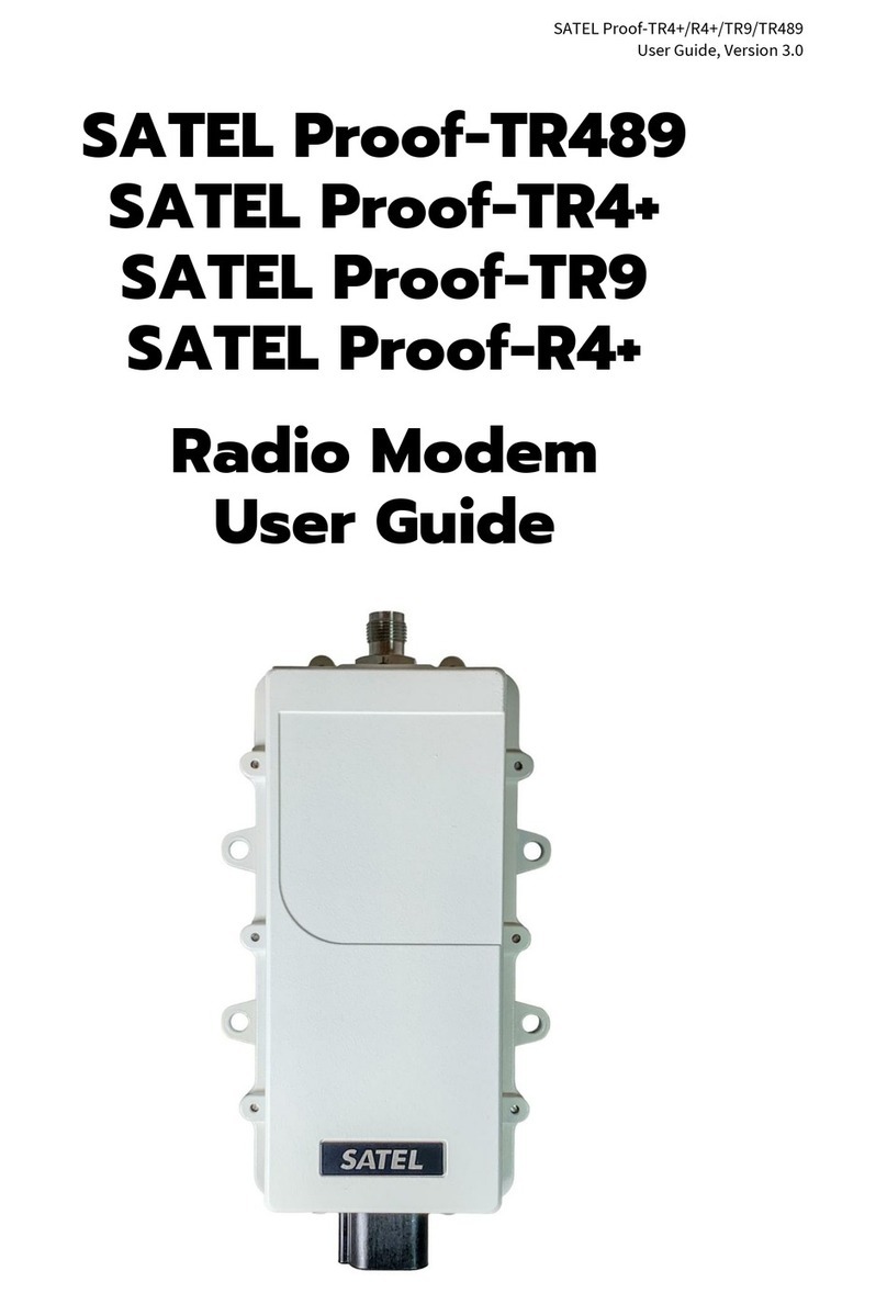
Satel SATELLINE-EASy Pro 35W User manual

SATELLINE-EASy Pro 35W
User Guide v.1.4
1
IMPORTANT NOTICE
All rights to this manual are owned solely by SATEL OY (referred to in this user guide as SATEL).
All rights reserved. The copying of this manual (without the written permission from the owner) by
printing, copying, recording or by any other means, or the full or partial translation of the manual
to any other language, including all programming languages, using any electrical, mechanical,
magnetic, optical, manual or other methods or devices is forbidden.
SATEL reserves the right to change the technical specifications or functions of its products, or to
discontinue the manufacture of any of its products or to discontinue the support of any of its
products, without any written announcement and urges its customers to ensure, that the
information at their disposal is valid.
SATEL software and programs are delivered ”as is”. The manufacturer does not grant any kind of
warranty including guarantees on suitability and applicability to a certain application. Under no
circumstances is the manufacturer or the developer of a program responsible for any possible
damages caused by the use of a program. The names of the programs as well as all copyrights
relating to the programs are the sole property of SATEL. Any transfer, licensing to a third party,
leasing, renting, transportation, copying, editing, translating, modifying into another
programming language or reverse engineering for any intent is forbidden without the written
consent of SATEL.
SATEL PRODUCTS HAVE NOT BEEN DESIGNED, INTENDED NOR INSPECTED TO BE USED IN
ANY LIFE SUPPORT RELATED DEVICE OR SYSTEM RELATED FUNCTION NOR AS A PART OF
ANY OTHER CRITICAL SYSTEM AND ARE GRANTED NO FUNCTIONAL WARRANTY IF THEY
ARE USED IN ANY OF THE APPLICATIONS MENTIONED.
Salo, FINLAND 2013
Copyright: 2013 SATEL Oy
No part of this document may be reproduced, transmitted or stored in a retrieval system in any form or by any means without the
prior written permission of SATEL Oy.
This document is provided in confidence and must not be distributed to third parties without the express permission of SATEL Oy.

SATELLINE-EASy Pro 35W
User Guide v.1.4
2
RESTRICTIONS ON USE
SATELLINE-EASy Pro 35W radio modems have been designed to operate on frequency ranges,
the exact use of which differs from one region and/or country to another. The user of a radio
modem must take care that the said device is not operated without the permission of the local
authorities on frequencies other than those specifically reserved and intended for use without a
specific permit.
The allowed max output power depends on the type of station.
SATELLINE-EASy Pro 35W is allowed to be used in the following countries, either on licence free
channels or on channels where the operation requires a licence. More detailed information is
available at the local frequency management authority.
Countries: AT, AU, BE, BG, CA, CH, CY, CZ, DE, DK, EE, ES, FI, FR, GB, GR, HU, IE, IS, IT, LT,
LU, LV, MT, NL, NO, PL, PT, RO, RU, SE, SK and US.
WARNING! Users of SATELLINE-EASy Pro 35W radio modems in North America should be
aware, that due to the allocation of the frequency band 406.0 – 406.1 MHz for government use
only, the use of radio modem on this frequency band without a proper permit is strictly forbidden.

SATELLINE-EASy Pro 35W
User Guide v.1.4
3
PRODUCT CONFORMITY
SATEL Oy hereby declares that SATELLINE-EASy Pro 35W radio modem is in compliance with the
essential requirements (radio performance, electromagnetic compatibility and electrical safety) and
other relevant provisions of Directive 1999/5/EC. Therefore the equipment is labelled with the
following CE-marking. The notification sign informs users that the operating frequency range of the
device is not harmonised throughout the market area, and the local spectrum authority should be
contacted before the usage of the radio modem is used.

SATELLINE-EASy Pro 35W
User Guide v.1.4
4
WARRANTY AND SAFETY INSTRUCTIONS
Read these safety instructions carefully before using the product:
-Warranty will be void, if the product is used in any way that is in contradiction with the
instructions given in this manual, or if the radio modem housing has been opened or
tampered with.
-The radio modem is only to be operated at frequencies allocated by local authorities, and
without exceeding the given maximum allowed output power ratings. SATEL and its
distributors are not responsible, if any products manufactured by it are used in unlawful
ways.
-The devices mentioned in this manual are to be used only according to the instructions
described in this manual. Faultless and safe operation of the devices can be guaranteed
only if the transport, storage, operation and handling of the devices are appropriate. This
also applies to the maintenance of the products.
-To prevent damage both the radio modem and any terminal devices must always be
switched OFF before connecting or disconnecting the serial connection cable. It should be
ascertained that different devices used have the same ground potential. Before connecting
any power cables the output voltage of the power supply should be checked.
-If the device uses an outdoor antenna, the antenna cable jacket must be grounded.

SATELLINE-EASy Pro 35W
User Guide v.1.4
5
TABLE OF CONTENTS
IMPORTANT NOTICE ......................................................................................... 1
RESTRICTIONS ON USE ..................................................................................... 2
PRODUCT CONFORMITY.................................................................................... 3
WARRANTY AND SAFETY INSTRUCTIONS ......................................................... 4
TABLE OF CONTENTS ........................................................................................ 5
INTRODUCTION .............................................................................................. 10
1SATELLINE-EASY PRO 35W TECHNICAL SPECIFICATIONS .................. 11
1.1 Default settings .................................................................................... 13
2OTHER FEATURES ................................................................................. 15
3SATELLINE-EASY PRO 35W SPECIAL FEATURES....................................... 16
3.1 Call Sign ............................................................................................... 16
3.2 Temperature protection of RF power amplifier ................................... 16
3.3 Protection of current ............................................................................ 17
4SERIAL INTERFACE .............................................................................. 18
5USER INTERFACE................................................................................. 19
5.1 LED-indicators ...................................................................................... 19
5.2 Display and push buttons .................................................................... 19
5.2.1 SATELLINE-EASy Pro 35W LCD-display after power-up................................................ 20
6CONNECTION INTERFACES ................................................................ 22
6.1 RS-232 interface................................................................................... 22
6.2 Connectors............................................................................................ 22
7RF INTERFACE ..................................................................................... 24

SATELLINE-EASy Pro 35W
User Guide v.1.4
6
7.1 Transmitter........................................................................................... 24
7.2 Receiver................................................................................................ 25
7.3 Priority RX/TX ....................................................................................... 25
7.4 Forward Error Correction ..................................................................... 26
7.5 Error checking ...................................................................................... 26
7.6 Dual radio function, separate RX/TX-frequencies .............................. 26
7.7 Free Channel Scan (FCS) ...................................................................... 27
7.8 User data whitening ............................................................................ 28
7.9 Pacific Crest and TRIMTALK compatibility............................................ 28
7.9.1 General................................................................................................................. 28
7.9.2 Configuration in Programming menu ........................................................................ 29
7.9.3 Configuration by using SL commands ....................................................................... 29
7.9.4 Settings ................................................................................................................. 29
7.9.5 Repeater function.................................................................................................... 32
7.9.6 Support for Local / Remote addresses ....................................................................... 32
7.9.7 Latency.................................................................................................................. 32
7.9.7.1 Transmission delays using Pacific Crest 4FSK on 25 kHz channel....................... 33
7.9.7.2 Transmission delays using Pacific Crest GMSK on 25 kHz channel..................... 33
8TRANSPARENT DATA TRANSMISSION ............................................... 34
8.1 Serial interface, data format ............................................................... 34
8.2 Handshake lines .................................................................................. 34
8.2.1 CTS-line ................................................................................................................ 35
8.2.2 CD-line ................................................................................................................. 35
8.2.3 RTS-line................................................................................................................. 36
8.3 Timing and delays during data transmission ..................................... 36
8.3.1 Data buffering in the radio data modem.................................................................... 36
8.3.2 Pause length .......................................................................................................... 37
8.3.3 TX delay ................................................................................................................ 38
8.4 Testing .................................................................................................. 38
9SETTINGS............................................................................................ 40
9.1 Programming Mode ............................................................................. 40
9.2 Changing parameters using a terminal device................................... 40
9.2.1 Changing the settings.............................................................................................. 40
9.2.2 Restoring factory settings.......................................................................................... 41

SATELLINE-EASy Pro 35W
User Guide v.1.4
7
9.2.3 Changing frequency (active radio channel frequency) ................................................. 42
9.2.4 Changing reference frequency.................................................................................. 43
9.2.5 Changing channel spacing ...................................................................................... 44
9.2.6 Changing radio settings .......................................................................................... 45
9.2.7 Free channel scan................................................................................................... 46
9.2.8 Changing addressing settings (primary and secondary RX- and TX-addresses) ................ 47
9.2.9 Changing serial port settings (Port 1)......................................................................... 48
9.2.10 Modification of handshaking functions ...................................................................... 50
9.2.11 Special functions..................................................................................................... 52
9.2.12 Modification of routing............................................................................................ 53
9.2.13 Activating tests........................................................................................................ 57
9.2.14 Restoring factory settings.......................................................................................... 57
9.2.15 Info....................................................................................................................... 57
9.2.16 Saving modified settings into the permanent memory .................................................. 58
9.2.17 Updating Firmware ................................................................................................. 58
9.3 Changing parameters using the LCD-display ..................................... 58
9.3.1 Changing frequency (frequency of the active TX/RX radio channel) ............................... 59
9.3.2 CHECKING/CHANGING THE REFERENCE FREQUENCY........................................... 61
9.3.3 Changing radio settings (transmitter power and receiver sensitivity) ............................... 62
9.3.4 Changing addressing.............................................................................................. 64
9.3.5 Changing serial port settings (Port 1)......................................................................... 65
9.3.6 Modification of handshaking functions ...................................................................... 66
9.3.7 Selecting special functions ....................................................................................... 67
9.3.8 Activating tests........................................................................................................ 67
9.3.9 Restoring factory settings.......................................................................................... 68
9.3.10 Adjusting the contrast of the LCD-display................................................................... 68
9.3.11 Saving modified values into the internal memory ........................................................ 69
9.4 Changing parameters using the SL-commands .................................. 69
9.4.1 Frequency.............................................................................................................. 70
9.4.2 Addressing............................................................................................................. 71
9.4.3 Radio parameters ................................................................................................... 71
9.4.4 Other functions ...................................................................................................... 72
10 REPEATER MODE AND ADDRESSING ................................................. 73
10.1 Repeater............................................................................................... 73
10.2 Addressing ........................................................................................... 74
10.2.1 Connection between two points................................................................................ 76
10.2.2 System of one base station and several substations ..................................................... 76
10.3 Using repeaters and addresses in the same system........................... 77
10.3.1 System with several repeaters ................................................................................... 77
10.3.2 Repeater chain using address pairs ........................................................................... 78
10.3.3 Repeater chain using dual addressing ....................................................................... 79
10.3.4 Redundant repeater chain........................................................................................ 79
11 MESSAGE ROUTING ........................................................................... 80

SATELLINE-EASy Pro 35W
User Guide v.1.4
8
11.1 Introduction to Message Routing......................................................... 80
11.1.1 Features of Message Routing ................................................................................... 81
11.1.2 Limitations of Message Routing ................................................................................ 81
11.1.3 Getting started with Message Routing........................................................................ 81
11.1.4 SaTerm and the configuration of the Message Routing ................................................ 82
11.1.5 Manual configuration of the Message Routing............................................................ 82
11.1.6 Configuration of the protocol in Message Routing ...................................................... 83
11.2 Operating modes of Message Routing ................................................ 84
11.3 Detailed description of Message Routing............................................ 85
11.3.1 Source Mode Routing.............................................................................................. 85
11.3.2 Virtual Mode Routing .............................................................................................. 85
11.3.3 Overhop function in Source Mode Routing ................................................................ 86
11.3.4 Network ID ............................................................................................................ 87
12 INSTALLATION ................................................................................... 88
12.1 Installation of a Radio Data Modem ................................................... 88
12.1.1 RS-232 Wiring ....................................................................................................... 88
12.1.2 Fuse...................................................................................................................... 89
12.1.3 Power supply.......................................................................................................... 89
12.2 Antenna installation ............................................................................ 90
12.2.1 Mobile equipment................................................................................................... 90
12.2.2 Base stations .......................................................................................................... 90
12.2.3 General antenna installation instructions ................................................................... 90
13 DESIGNING SYSTEMS......................................................................... 94
13.1 Factors affecting the quality and distance of the radio connection .... 94
13.2 Radio field strength ............................................................................. 95
14 CHECK LIST ......................................................................................... 96
15 ACCESSORIES...................................................................................... 97
15.1 RS-232 cables and adapters................................................................ 97
15.2 Power cable.......................................................................................... 97
15.3 RF-cables .............................................................................................. 97
15.4 Antennas .............................................................................................. 98
15.5 Filters and lightning protectors ........................................................... 98
16 APPENDIX A ....................................................................................... 99

SATELLINE-EASy Pro 35W
User Guide v.1.4
9
17 APPENDIX B ..................................................................................... 100
17.1 Functional delays ............................................................................... 100
17.2 Transmission related delays .............................................................. 100
17.2.1 Transmission delays when the radio TX frequency is changed......................................101
17.2.2 Transmission delays when using a 12.5 kHz radio channel .........................................101
17.2.3 Transmission delays using a 25 kHz radio channel ....................................................103

SATELLINE-EASy Pro 35W
User Guide v.1.4
10
INTRODUCTION
SATEL OY is a Finnish electronics and Telecommunications Company specialising in the design
and manufacture of wireless data communication products. SATEL designs, manufactures and
sells radio modems intended for use in applications ranging from data transfer to alarm relay
systems. End users of SATEL products include both public organisations and private individuals.
SATEL OY is the leading European manufacturer of radio modems. SATEL radio modems have
been certified in most European countries and also in many non-European countries.
SATELLINE-EASy Pro 35W is an IP67 classified UHF radio modem with a high power (35 W)
transmitter, wide 70 MHz tuning range (403...473 MHz) in one hardware and selectable channel
spacing. The SATELLINE-EASy Pro 35W can offer radio speeds up to 19.2 kbps and has a
selectable serial interface speed between 300 … 38 400 bps.
SATELLINE-EASy Pro 35W includes a built-in LCD display, offering the user both new features and
increased flexibility. No longer do you have to rely on access to a PC or terminal device to check
or alter the configuration of the unit, now this can be achieved by viewing the LCD-display and
using the four (4) push buttons. The display is also a useful tool in testing the radio connection
between radio modems.
SATELLINE-EASy Pro 35W facilitates the construction of large radio networks using the built-in
Message Routing function, which is both fully transparent to the user and can be used with most
system protocols.
The radio modem also offers option of error correction, utilising the FEC-method (Forward Error
Correction). FEC can be used to minimise errors caused by noisy channels.

SATELLINE-EASy Pro 35W
User Guide v.1.4
11
1SATELLINE-EASy Pro 35W technical specifications
SATELLINE-EASy Pro 35W complies with the following international standards:
o EN 300 113-2 (RF-requirements)
o EN 301 489 (EMC-requirements)
o EN 60950 (Safety Standard)
o FCC CFR47 part 90
RECEIVER
TRANSMITTER
Note!
Frequency Range
403...473 MHz
Tuning Range
70 MHz
Channel Spacing
12.5 kHz / 20 kHz / 25 kHz
Programmable
Spurious Radiations
< 2 nW
According to EN 55022 and
FCC CFR47 part 90
Duty Cycle 35W *)
100% (@22°C) 20 min
100% (@35 °C) 13 min
40% No limit
Duty Cycle 10W *)
100% (@22°C) No limit
100% (@35 °C) 50 min
40% No limit
Frequency Error
Tolerance < 1 kHz
Sensitivity
-114 dBm @ 12.5 kHz
-111 dBm @ 25 kHz
(BER < 10 E-3)
FEC ON
See: Note 1
Co-channel Rejection
>-12 dB
FEC ON
Adjacent Channel
Selectivity
> 47 dB @12.5 kHz
> 52 dB @ 25 kHz
FEC ON
Selectivity
67 dB @ ±50 kHz
FEC ON
Intermodulation
Attenuation
> 60 dB
FEC ON
Blocking
> 86 dB
FEC ON
Spurious Rejection
> 60 dB
FEC ON
Power Consumption
< 1.8 W
110 W typical@ 35 W,
min 12 Vdc
Power Save Mode
Consumption SLEEP State:0,4 W typical
Communication Mode
Half-Duplex
Type of Emission
F1D
Carrier power
10, 20, 25, 35 W / 50 ohm
Adjacent Channel
Power
According to EN 55022 and
FCC CFR47 part 90
Carrier power stability
+ 2 dB / - 3 dB
*) If high output power is used continuously or with a high cycle, the equipment generates excess heat. The output
power is automatically decreased when necessary to prevent overheating. Typical operating times are shown in the
chart with different output powers and duty cycles @ 22°C and 35 °C (see chapter 3.2).
Note 1
Due to radio electronic design, the receiver is about 6 – 15 dB less sensitive on the following frequencies:
403.000, 416.000, 429.000, 442.000, 455.000, 468.000, 409.5875 and 469.200 MHz.

SATELLINE-EASy Pro 35W
User Guide v.1.4
12
DATA MODEM
Timing
RS-232
Electrical Interface
RS-232
Interface Connector
8-pin ODU
Data speed of
I/O-interface
300 – 38400 bps
Data speed of Radio
Interface
19200 bps (25 kHz channel) /
9600 bps (12.5 / 20 kHz channel)
Data Formats
Asynchronous RS-232
Modulation
4FSK, GMSK, (PacificCrest, TRIMTALK **)
**) TRIMTALK is a trademark of Trimble Navigation Ltd.
GENERAL
DC input ranges
Nominal voltage : +9...+16 V
DC
4-pin ODU
MINI-Snap Size 1
Temperature Ranges
-25 °C...+55 °C
Complies with
standards
-40 °C...+75 °C (absolute min / max)
Functional
-40 °C... +85°C
Storage
Antenna Connector
TNC, 50 ohm, female
Construction
Aluminium housing
Size L x W x T
171 x 138 x 70 mm
Weight
1360g
IP Classification
IP67 (NEMA 6)
OTHER MEASUREMENTS
ESD-failure threshold
8 kV contact, 15 kV air discharge
Immunity test
10V/m

SATELLINE-EASy Pro 35W
User Guide v.1.4
13
1.1 Default settings
SATELLINE-EASy Pro 35W is shipped with the following default settings (unless otherwise
specifically agreed):
DEFAULT VALUES OF THE ADJUSTABLE SETTINGS (user can change settings later on)
Setting
Default value
Range
Radio frequency
Operating TX frequency
438.000 MHz
Range: 403 - 473 MHz
Operating RX frequency
438.000 MHz
Range: 403 - 473 MHz
Reference Frequency
438.000 MHz
Range: 403 - 473 MHz
Channel Spacing
12.5 kHz
Range: 12.5, 20 or 25 kHz
Radio settings
Tx Power
35 W
Range: 10, 20, 25 and 35 W
Signal threshold
-115 dBm
-80 … -118 dBm
FCS
OFF
ON/OFF
Tx-Start Delay
0 ms
0-65535 ms
Radio Compatibility
SATEL 3AS
SATELLINE-3AS, Option1=PCC 4-FSK,
Option 2=PCC GMSK, 3=TrimTalk 450s (P),
4=TrimTalk450s (T), 5=PCC-FST
Addressing
RX Address
OFF
ON/OFF
TX Address
OFF
ON/OFF
RX addressing to RS port
OFF
ON/OFF
TX address auto switch
OFF
ON/OFF
Serial port 1
Status
ON
ON/OFF
Interface
RS-232
Fixed
Data speed
9600 bps
300, 600, 1200, 2400, 4800, 9600, 19200,
38400 bps
Data bits
8
7, 8, 9
Parity bits
None
None, Even, Odd
Stop bits
1
1, 2
Handshaking
Handshaking lines apply to the DATA-port.
CTS
Clear to send
Clear to send, TX buffer state
CD
RSSI threshold
RSSI- threshold, Data on channel,
Always ON, External Antenna Control
RTS
Ignored
Ignored, Flow Control, Reception Control
Pause length
3 bytes
3 … 255 bytes
Additional setup
Error correction
OFF
ON/OFF
Error check
OFF
ON/OFF
Repeater
OFF
ON/OFF
SL-commands
ON
ON/OFF
Priority
TX
RX/TX
FullCR16 Check
OFF
ON/OFF
Routing
OFF
ON/OFF
Tests
OFF
ON/OFF
The power cable (+Vband GND) must be connected to a power supply with a proper output
voltage (+9…+16 VDC) and with a minimum output current of 15A.

SATELLINE-EASy Pro 35W
User Guide v.1.4
14
When creating a test connection, you can use Windows™ based SATEL Configuration Manager
(available for free from authorised SATEL dealers or directly from SATEL Customer Support),
HyperTerminal (which is included in most the Windows™ based operating system packages), or
almost any other terminal program.
Basic settings for the serial port of the host computer, when using a terminal program to
communicate with SATEL radio modems, are as follows: “COM1, 9600 bps, 8-bit data, none
parity, 1 stop bit”.
If the serial port designated as COM1 in the host computer is reserved, any other free serial port
in the host computer can be used (with the settings listed).
Note: If you want to change the settings of a radio modem using the Programming Mode of
the radio modem with the help of an external ter
minal, the data speed of the terminal must
be 9600 bps.

SATELLINE-EASy Pro 35W
User Guide v.1.4
15
2OTHER FEATURES
SATELLINE-EASy Pro 35W radio modem fulfils the IP67 (NEMA 6) standard. With an IP67 rating a
product will be totally protected against dust and remain completely sealed when immersed in
water to a depth between 15 cm and 1 meter.
SATELLINE-EASy Pro 35W modem is equipped with a high power 35 W transmitter. It is designed
for easy mobile use in demanding field conditions.
The SATELLINE-EASy Pro 35W is equipped with a liquid crystal display (LCD) and a keypad, used
to indicate the current operating status, as well as for changing the operating channel and power
level of the radio modem.

SATELLINE-EASy Pro 35W
User Guide v.1.4
16
3SATELLINE-EASy Pro 35W SPECIAL FEATURES
3.1 Call Sign
SATELLINE-EASy Pro 35W has a CALL SIGN identifier -feature required in some countries. A call
sign can be formally assigned by a government agency, informally adopted by individuals or
organizations, or even cryptographically encoded to disguise identity of a station.
A call sign is an FCC (in US) or other regulatory authority assigned identifier that is issued along
with the license for operating a radio modem. This field is for entering your call sign. The modem
automatically broadcasts the specified call sign periodically. If this field is empty, there is no call
sign information.
Call sign setup can be found in PROG-menu clause Radio settings and further in its sub clause
Call sign. Call sign has three (3) different setups. With
Call Sign Mode
you can set Morse code
transmission ON or OFF.
Call Sign ID
defines which Morse code will be transmitted. Only capital
letters and numbers are allowed. If the digits are wrong kind, there will be message: Value error.
Small letters will be converted to capital letters automatically. If
Call Sign ID
field remains empty,
the Call Sign transmission will not be activated.
Call Sign Timer
is the transmission delay of Morse
codes. Minimum and default transmission time is 15 minutes.
During Call sign transmission the CTS-line of the modem is not in active state. This is to inform
terminal equipment that the modem is not ready to neither receive data from serial port nor
forward it. The modem deletes all data (also SL commands), which has arrived to serial port
during call sign transmission. Call sign transmission lasts 1-4 seconds depending on the number
of digits.
3.2 Temperature protection of RF power amplifier
RF power amplifier is protected against overheating. The power of transmitter is lowered step by
step if the inner temperature exceeds certain levels as shown below.
Temperature inside a modem
Carrier power
Over 75°C
25 W
80°C
20 W
85°C
10 W
90°C
0 W (transmitter OFF)
When the ambient temperature is under 30°C and transmitter duty cycle does not exceed 40%,
the temperature inside the modem does not exceed the trigger level.

SATELLINE-EASy Pro 35W
User Guide v.1.4
17
The internal temperature is measured in the beginning of every transmission and at once when
modem cools down. The carrier power increases with falling temperature so that at 88°C carrier
power goes to 10W, at 83°C to 20W, at 78°C to 25W and at 73°C the modem operates again
at the full 35W carrier power.
3.3 Protection of current
In case of a bad antenna impedance matching the current consumption of the Power Amplifier
may be too high. For this reason the maximum current is limited to 12 A. If the current tends to
increase over 12 A, the automatic power control decreases the power level until the current drops
under 11.5 A. LCD indicates the actual power level of the transmitter. A new transmission starts
always with the nominal power level. The power control scheme is applied only when the nominal
power level is 35 W.

SATELLINE-EASy Pro 35W
User Guide v.1.4
18
4SERIAL INTERFACE
The radio modem is referred to as DCE (Data Communication Equipment) whereas the PC is
referred to as DTE (Data Terminal Equipment). SATELLINE-EASy Pro 35W includes a 8 pin ODU
which contains all the connections required to establish communication between the radio
modem, acting as the DCE, and the PC, acting as the DTE.
All EMC-requirements set forth by authorities have been taken into account in the design of the
radio modem. The radio modem user is thereby not required to take any special actions
regarding EMC-shielding (of the radio modem).
The radio modem has one serial port, Port 1 which complies with the RS-232 standard.
Signal
8-pin ODU
RD
4
TD
5
CTS
2
RTS
1
GND
3
MODE
6
Description of pins:
•RD = Receive Data. Output of the data received from the radio modem to the DTE.
•TD = Transmit Data. Input of the data to be transmitted from the DTE to the radio modem.
•CTS = Clear To Send.
•RTS = Request To Send.
•MODE = operational mode. When the MODE-line is connected to ground (GND), the
radio modem enters the Programming Mode,which is used to change the settings of the
radio modem (i.e. configuration, set-up). If the MODE-line is not connected, the radio
modem will enter the Data Transfer Mode, in which data can be transmitted and received.
The Programming Mode is used only when installing a radio modem and changing the
operational parameters of a network. Normally the radio modem is always in the Data
Transfer Mode.
•GND = both the negative pole of the operating voltage and the signal ground.

SATELLINE-EASy Pro 35W
User Guide v.1.4
19
5USER INTERFACE
5.1 LED-indicators
There are five (5) LED indicators on the front panel of the radio modem, and they give an
indication of the status of the serial port and the radio interface:
Description of the LED-
indicators:
5.2 Display and push buttons
SATELLINE-EASy Pro 35W includes a LCD-display with a backlight. In the Data Transfer Mode the
display will show the operating settings of the radio modem, for example the radio field strength
and the supply voltage. By using the push buttons and the LCD-display, it is possible to change
most of the settings of the radio modem, without the need for an external terminal. The display
backlight illuminates automatically as soon as a button is pressed.
The radio modem will shift into the Programming Mode by pressing the SETUP-push button ().
When activated the menu shows a listing of the changeable parameters.
With the help of the main menu, sub-menus can be selected which in turn can be used to change
the settings. You can always return to the previous higher level of the menu structure by pressing
the CANCEL (or BACK) push button (●). Pressing the or button changes settings or moves
in the menu. Selections are confirmed by pressing the SELECT or SET button. In case of numerical
values the digit to be changed is selected by pressing the NEXT button (see following page).
LED
Indication
OFF
Red
Orange
Green
RTS
RTS-line status
Inactive
Active
CTS
CTS-line status
Inactive
Active
TD
TD-line status
No data
Data
Test Tx active
RD
RD-line status
No data
Data
CD
Radio status
No signal
Transmission
Noise
Reception

SATELLINE-EASy Pro 35W
User Guide v.1.4
20
5.2.1 SATELLINE-EASy Pro 35W LCD-display after power-up
The display shows the basic information which is revolving automatically in 5 seconds.
Display in Data Transfer Mode (transmit/receive mode)
n-120 11.5V
TX 438.000.000
RX 438.000.000
TX:35W SETUP
n-120: Field strength of last received
transmission or noise level.
11.5 = Supply voltage/battery level
indicator.
TX/RX = Operational TX and RX frequency.
n-120 11.5V
Compatibility:
Satel 3AS
TX:35W SETUP
Satel 3AS is one of the radio protocols.
TX:35W = Current output transmission
power is 35W
n-120 11.5V
TX Power: 35W
Spacing: 25 kHz
TX:35W SETUP
TX Power= Output transmission power.
Spacing= Channel spacing
n-120 11.5V
Ref 438.000.000
Com: 9600N81
TX:35W SETUP
Ref.= Reference frequency
Communication Port Settings:
9600=Baud rate. N=None parity
8=Parity bits. 1=Stop bits.
INFO - SETUP
By pressing cancel/back button (●) the modem goes to detailed information about the modem’s
settings.
By pressing SETUP button () the modem goes to the programming menu.
Table of contents
Other Satel Radio Modem manuals

Satel
Satel SATELLINE-3AS VHF YM5000 User manual

Satel
Satel SATEL-EASy+ YM6015 User manual

Satel
Satel SATELLINE-3ASd Epic Pro 35W User manual

Satel
Satel SATEL-EASY PRO+ User manual

Satel
Satel SATELLINE-3AS VHF YM5000 User manual

Satel
Satel SATELLAR XT 5R User manual

Satel
Satel SATELLINE-2ASxE User manual

Satel
Satel SATEL-3AS-125 User manual

Satel
Satel M2M User manual

Satel
Satel Proof-TR489 User manual