RFID DT44 User manual

Installation & Operations Manual
Model DT44
UHF RFID Desktop USB
Tag Reader & Programmer

14190 E. Jewell Avenue Suite 4 Aurora CO 80012 TEL: 303-366-1234
www.rfidinc.com
Model DT44 902-928 MHz Operations Manual
2
Table of Contents
How To Contact Us ................................................................................................................................ 2
Product Part Numbers & Accessories................................................................................................... 3
Specifications.......................................................................................................................................... 3
Section 1 –General Information............................................................................................................. 3
Section 2 - Quick Start Installation Guide.............................................................................................. 4
Software................................................................................................................................................. 4
Section 3 - Operating the Reader............................................................................................................ 4
Work Mode............................................................................................................................................ 4
Operation Modes................................................................................................................................... 5
Writing (Programming) Tags (part 1)................................................................................................... 6
Understanding Tag Memory ................................................................................................................. 7
Writing (Programming) EPC Data (part 2)........................................................................................... 9
Tag Memory Chip Options.................................................................................................................. 10
More about the DT44 Control Program.............................................................................................. 11
Locking................................................................................................................................................ 11
Lock Password .................................................................................................................................... 11
Troubleshooting................................................................................................................................... 12
WARRANTY ....................................................................................................................................... 13
How To Contact Us
303-366-1234 x1001
303-910-5447 cell 9am to 6pm PST
303-366-1234 x 1007
303-366-1234 x 1003 8am to 6pm MST
303-808-2228 cell
303-378-9500 cell 7am to 9pm CST

14190 E. Jewell Avenue Suite 4 Aurora CO 80012 TEL: 303-366-1234
www.rfidinc.com
Model DT44 902-928 MHz Operations Manual
3
Product Part Numbers & Accessories
Part Number
Description
808-0044-00
Model DT44 Desktop Reader/Programmer, 4 inches square, USB
730-0052-10FT
USB Cable, 10', 2.0 S Male to B Male
Note: 5’ USB cable in included with Reader
Specifications
Mechanical:
Measurements:
107x107x22.5mm
4.2”x4.2”x.87”
Material:
ABS Housing
Weight:
4 Ounces
114 grams
Certifications:
RoHS III
REACH
CE
FCC Part 15 & ETSI
SIL2
Free of BBP, DEHP, DBP, DIBP
RF:
Standard:
ISO 18000-6c
EPC Gen2
Frequency:
902-928 MHz (US)
865.6-867.6 MHz (EU)
Power:
USB
Security:
Password Protected
Kill Tag Option
Environmental:
Storage Temp:
-77°F to +185°F
-25°C to +85°C
Temp, Operating:
-77°F to +185°F
-25°C to +85°C
Life:
40 Year Shelf Life
Ingress Protection:
IP65
Section 1 –General Information
This manual provides information pertaining to the installation and operation of the Model DT44
UHF 902-928 MHz Reader & Programmer. This Reader contains an internal Antenna and is powered
via its USB connection.
This Reader is capable of operating with any ISO standard 18000-6C EPC Gen2 RFID Tag. Tag
memories vary by chip. Please reference page 7 for a full list of Tag memory chips.
This Reader is simple to use, plug & play. The Reader operates as both a transmitter and receiver,
providing an ultra-high frequency electromagnetic field at 902-928 MHz (North America) or other
depending upon the geographical location of use, to energize and activate an electronic transponder
(RFID Tag). Once the Tag is energized it modulates its data back to the Reader which in turn detects
and demodulates this data for delivery to the USB port.

14190 E. Jewell Avenue Suite 4 Aurora CO 80012 TEL: 303-366-1234
www.rfidinc.com
Model DT44 902-928 MHz Operations Manual
4
Section 2 - Quick Start Installation Guide
Software
Go to https://www.rfidinc.com/resource-center/ and choose the DT44 option. Download the DT44
zip file. Once downloaded, extract the entire zip folder as the program (app file named DT44Control)
will not work without the two dll files. Save those three files to a folder on your PC and create a
shortcut to the DT44Control software program on your desktop. Open the DT44Control file. You
may have to temporarily turn off your firewall especially if you have Norton. The file is safe, do not
worry. Once opened you should see this screen:
Connect the Reader to a Windows based PC or laptop via the USB cable. You should hear a beep and
see multi-colored lighting on the Reader face, and after some time the multi-colored lighting should
stop flashing but remain illuminated.
In the program, do not use the Serial Connect area. This is a function for other Readers. Under the
USB Connect section, select “ScanUSB.” Use the pulldown box and select \USB-Open, then select
“OPEN(O).” The rest of the program screen should then go from greyed out to normal print.
Section 3 - Operating the Reader
The program should be defaulted to EPC in the Inquiry Area, Bank of 01, Word Start of 02 and Word
Count of 06. If not, please set as such for tutorial uses of this product manual.
Work Mode
From the Work Mode pulldown you can select one or the other and then select Set, Start, Stop.

14190 E. Jewell Avenue Suite 4 Aurora CO 80012 TEL: 303-366-1234
www.rfidinc.com
Model DT44 902-928 MHz Operations Manual
5
AnswerMode –Tags will not read or report until Start is selected. Tags will continue to read and
report continuously. Select Stop to discontinue reading Tags or remove the Tags from the Reader.
There is no Filter Time option in this mode. Filter Time is an option to choose at what intervals in
time of seconds to read a Tag.
ActiveMode –Tags will read without needing to select Start but will not report to the display area
until Start is selected. A Tag will read continuously until Filter Time is set. The Filter Time option
allows for a Tag to be read and reported only once per the amount of Filter Time set. Filter Time only
works if one Tag is present. Again, if you select Stop in this mode, a Tag will continue to be read
(beeping) but not show in the display area, assuming no Filter Time is set. In the ActiveMode, think
of Start and Stop as starting and stopping Tag data to the display area.
Filter Time - Single Report Mode is the operation of reading a Tag only once. Go to the Filter Time
field and enter an amount of time in seconds, say 5, then select Set. Remember, you must be in the
ActiveMode. If you present a single Tag to the Reader it will now read only once. Whether the Tag
is present to the Reader or not, it will be read only every 5 seconds. Increase the time if you’d like a
longer interval of the Single Read Mode.
Notes:
Maximum time setting is 255 seconds (4 minutes, 15 seconds).
If a second Tag is introduced to the Reader the time filter clock will begin anew cancelling the time
filter for the initial Tag read. If more than one Tag is present to the Reader, they will all read
continuously. The Time Filter only applies to a single Tag.
Operation Modes
There are two types of operation to read Tags, Inventory and Single Tag.
Inventory Operation –Multiple Tag readings using the “Start” and “Stop” buttons, the Reader will
read a Tag or Tags repeatedly and display their data in the lower data display area once Start is
selected. Both AnswerMode and ActiveMode can perform in Inventory Mode. The Inventory mode
ignores any defined Bank, Word Start and Word Count settings and reads the area of memory as
defined in the Inquiry Area when you select “Start.”
At any point in time, if you wish to select and focus on one Tag only, clicking that data in the lower
data display area will copy the data to the upper data display field. In the Inventory Operation, the
number of times a Tag was read can be viewed under “Cnt.” Note, once you select Start again all
previous Tag data will disappear from the lower data display area although any data in upper data
display area from a previous operation will remain. You can delete it or ignore it.
Single Tag Operation –Aka single Tag reading/writing via use of the “Read” and “Write” button.
This gives you the ability to command the Reader to read and display a Tag in the upper data display
area, the smaller rectangular data field above Bank. It is best to be in the AnswerMode else the
Reader will continually beep when a Tag is present and you must have both the Inquiry Area as well

14190 E. Jewell Avenue Suite 4 Aurora CO 80012 TEL: 303-366-1234
www.rfidinc.com
Model DT44 902-928 MHz Operations Manual
6
as the Bank, Word Start and Word Count defined correctly. Place a Tag on the Reader and simply
select “Read.” If you have two Tags on the Reader, one or the other will display, but not both.
Inquiry Area –When using the Single Tag Operation (Read and Write buttons), regardless of what is
shown in the Inquiry Area, you can read different banks of memory by defining the Bank, Word Start
and Word Count, and then selecting Read.
In the Inventory operation where Tags are read continually, the number of times a Tag was read can
be viewed under “Cnt.” Note, once you select Start again all previous Tag data will disappear from
the viewing screen. In this example we read a single Tag with the data of 3008 33B2 DD09 0140
5C00 5242 36 times. Notice that by default the area of memory to be read is set to Bank to 01, the
Word Start to 02, and the Word Count (or length of memory) to 06. This is the Tag’s basic most used
memory known as EPC and is all explained in the next section.
Writing (Programming) Tags (part 1)
If you intend to Write (program) a Tag, it’s important to understand the structure of a UHF RFID
Tag’s memory.

14190 E. Jewell Avenue Suite 4 Aurora CO 80012 TEL: 303-366-1234
www.rfidinc.com
Model DT44 902-928 MHz Operations Manual
7
Understanding Tag Memory
Tag data is represented in Hexadecimal format, meaning characters of 0 to 9 and A to F. Each UHF
RFID memory chip consists of 3 sections:
TID –24 characters of unique ROM data. This data cannot be changed and is guaranteed unique.
EPC –24-40 characters of writable data.
User Memory –Varying amounts of additional writeable data variable by chip model.
Memory mapping is organized by Blocks and Word Addresses. A Word is 16 bits, also known as 2
bytes and appears as 4 hex characters. The last 4 characters in the example Tag read above of 5242 is
16 bits, aka 2 bytes or 1 Word.
Viewing the table below, think of the mapping as streets and house addresses. In this small town,
we’ve only got 4 streets, Block 00, 01, 02, and 03. Each house (address) has a function or contains
Tag data.
Block 00 allows the functions of killing a Tag such that it is rendered inoperable, or setting a
password so that a Tag can only be re-programmed if that password is known. As of this writing, we
have not included the Kill Tag option, only the password option exists. Default password is set to
00000000. Setting a password only limits the reprogramming of Tag data. Tag data can always be
read regardless of whether a password is set or not. If you wish to set a password, it is critical that
each password is documented. If forgotten, there is no way to recover that password.
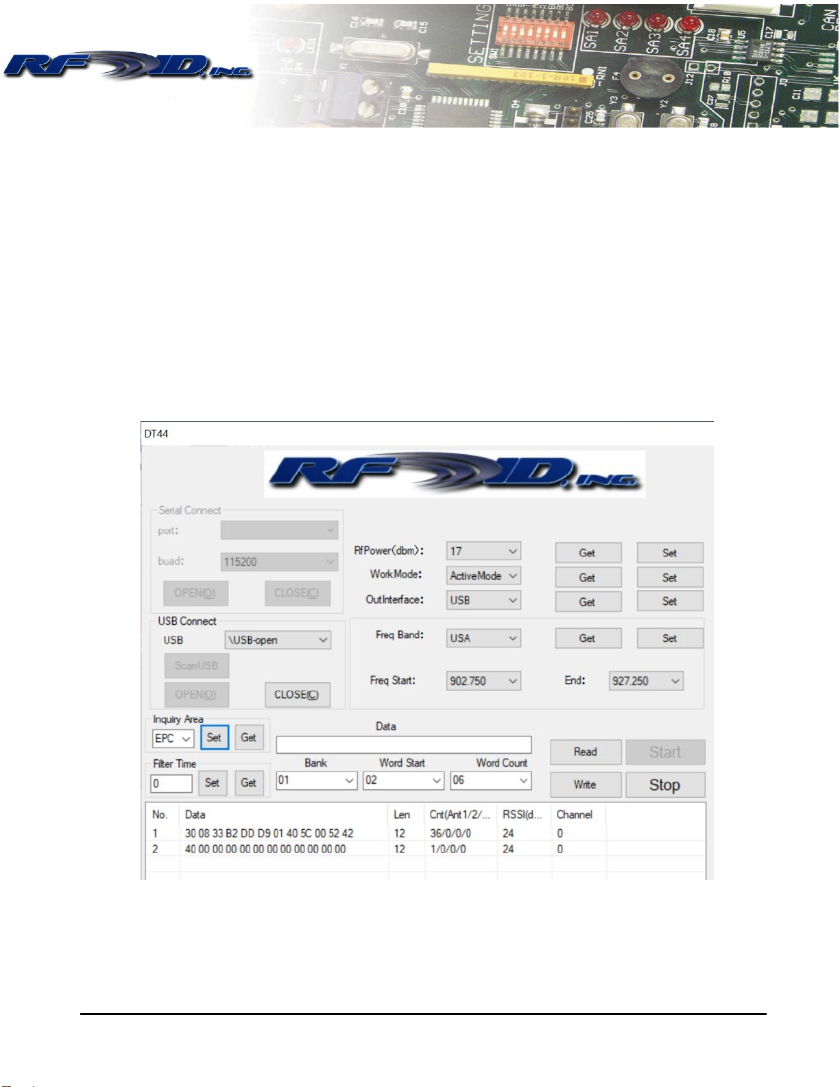
Block 01 has 8 addresses, of which 00 and 01 are functions, not accessible by the user. CRC in
address 00 is a check sum to ensure data is not corrupt. Protocol Control tells us if User Memory
contains data. A Tag reporting 3000 tells us the user memory has not been programmed, while 3400
alerts us that there is more data present in User Memory. Note that sometimes these are represented
as 5000 and 5400 when EPC length is increased to 40 characters. Notice addresses 02 to 07, EPC
data. This range encompasses 6 addresses, each being 4 characters, and 4 x 6 = 24, which is the
length of our EPC data in the example above. If we were to look into address 07 only, we’d see the
last 4 characters of 5242, also known as the last Word.
Block 02 is the TID data, ROM, always unique, cannot be altered. If you’d like to operate with TID
data, use the pulldown menu in the Inquiry Area section, choose TID and Set.
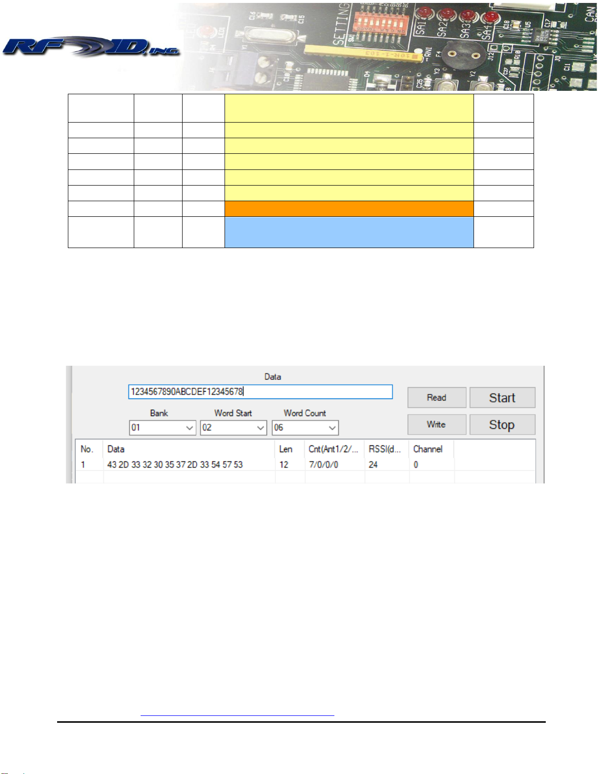
Block 03 begins User Data, which is basically extra data beyond the 24 characters of EPC. If you’d
like to read or write User Data, set the Inquiry Area to User Data first, and Set. Some memory chips
have zero User Data, another may have 512 bits, and divided by 4 would equal 128 characters of data
divided into 32 Words (4 data characters). See the section Tag Memory Chip Options on page 10.

14190 E. Jewell Avenue Suite 4 Aurora CO 80012 TEL: 303-366-1234
www.rfidinc.com
Model DT44 902-928 MHz Operations Manual
8
Block or
Bank
Word
Address
Description
Memory
Size
00
00
Kill Password
32 bits
01
Access Password
32 bits
01
00
CRC-16
16 bits
01
Protocol Control (this is the first appearance of Tag data)
3000 = no data in user memory
3400 = data present in user memory
16 bits
02
EPC Data (total EPC data in sub-addresses 02-07 = 96 bits
16 bits
03
EPC Data
16 bits
04
EPC Data
16 bits
05
EPC Data
16 bits
06
EPC Data
16 bits
07
EPC Data
16 bits
02
TID (tag identification) ROM, cannot be changed
96 bits
03
Varies
00-?
User Memory up to 61,400 bits
Varies
Let’s take a look at the following EPC Tag data:
432D 3332 3035 372D 3354 5753
Now let’s use the same table above and fill in this Tag data broken into 16 bits (1 word, 4 characters)
increments.
Block or
Bank
Word
Address
Data
Description
Memory
Size
00
00
Kill Password
32 bits
01
Access Password
32 bits
01
00
CRC-16
16 bits
01
3000
Protocol Control (this is the first 4 Tag data bytes)
3000 = no data in user memory, EPC Length 6 words
(factory default)
3400 = data present in user memory, EPC Length 6
words (factory default)
5000 = no data in user memory, EPC Length 10 words
5400 = data present in user memory, EPC Length 10
words
16 bits

14190 E. Jewell Avenue Suite 4 Aurora CO 80012 TEL: 303-366-1234
www.rfidinc.com
Model DT44 902-928 MHz Operations Manual
9
02
432D
EPC Data (total EPC data in sub-addresses 02-07 = 96
bits
16 bits
03
3332
EPC Data
16 bits
04
3035
EPC Data
16 bits
05
372D
EPC Data
16 bits
06
3354
EPC Data
16 bits
07
5753
EPC Data
16 bits
02
TID (tag identification) ROM, cannot be changed
96 bits
03
Varies
00-?
User Memory up to 61,400 bits
Varies
Writing (Programming) EPC Data (part 2)
Let’s write a Tag’s EPC data from 432D 3332 3035 372D 3354 5753 to 1234 5678 90AB CDEF
1234 5678. Remember to set Inquiry Area to EPC and memory mapping to Bank 01, Word Start 02,
and Word Count (word length) to 06. Enter the new data of 1234567890ABCDEF12345678 into the
upper white rectangular Data field.
In the AnswerMode, select Stop, place a Tag on the Reader, select Write, then Start and Stop to read
and confirm the Write was successful by viewing lower data display area which should now match
that in the upper data display area. Replace with a new Tag, enter new Tag data and repeat to
continue. You do not have to select Start, you can also select Read to read the Tag only once and
output to the upper data display area.
Let’s write 12 characters into the first area of User Memory using 1111222233334444. In the
AnswerMode, choose Stop, set Bank to 03, Word Start to 00 and Word Count to 04, which means we
are going to program addresses 00, 01, 02 and 03. Type 111222233334444 into the upper data
display field and select Write. You do not have to change the Inquiry Area to User Data in order to
Write. You do need to choose the Inquiry Area if you intend to read and confirm the User Data was
programmed successfully. Change the Inquiry Area to User Data, Set, Start and Stop to confirm.
For a more advanced and detailed explanation, please download and view video available under
DT44 link here https://www.rfidinc.com/resource-center/.

14190 E. Jewell Avenue Suite 4 Aurora CO 80012 TEL: 303-366-1234
www.rfidinc.com
Model DT44 902-928 MHz Operations Manual
10
Tag Memory Chip Options
UHF RFID Tags contain a EEPROM with encoded data in the TID and EPC memory sections. Tags
have no finite life for read only operations and a finite life of 100k writes. There exists a plethora of
UHF Tag memory chips available shown in the table below that RFID, Inc. can supply in a finished
RFID Tag. Table lists chip manufacturer, model, and amounts of TID, EPC, and User memory.
RFID, Inc. can supply a data sheet on each chip option. If you’d like assistance choosing a particular
chip fitting your needs, please consult with us.
Alien
Higgs3
Higgs4
HiggsEC
Higgs9
TID (ROM)
64 bits
64 bits
48 bits
48 bits
UID (EPC)
96 to 480 bits
128 bits
96-128 bits
496 bits
User Memory
512 bits
128 bits
128 bits
688 bits
EM
EM4123
EM4124
EM4126
EM4324
EM4325
EM4423 dual HF NFC/UHF
EM4425 dual HF NFC/UHF
TID (ROM)
64 bits
64 bits
32 bits
64 bits
48 bits
96 bits
UID (EPC)
0 bits
96 bits
208 bits
96 bits
352 bits
64-160 bits
User Memory
0 bits
0 bits
0 bits
720 bits
3072 bits
0 bits
96 bits
Up to 480 bits
Up to 2048 bits less EPC
Fujitsu (FRAM)
MB97R88110
MB97R88120/8130
MB97R8050
TID (ROM)
208 bits
208 bits
176 bits
UID (EPC)
480 bits
480 bits
160 bits
User Memory
61,400 bits
61,400 bits
0 bits
Impinj
M4D
M4E
M4QT
M4i
MX-8k
Monza R6P
Monza R6
Monza R6A
Monza R6B
Monza 5
M730
M750
TID (ROM)
96 bits
96 bits
96 bits
96 bits
96 bits
96 bits
96 bits
96 bits
96 bits
96 bits
96 bits
96 bits
UID (EPC)
Up to 128 bits
Up to 496 bits
Up to 128 bits
Up to 256 bits
Up to 128 bits
Up to 128 bits
96 bits
96 bits
Up to 128 bits
128 bits
128 bits
96 bits
User Memory
32 bits
128 bits
512 bits
480 bits
8,192 bits
Up to 64 bits
0 bits
0 bits
32 bits
32 bits
0 bits
32 bits
NXP
UCODE 7
UCODE 7m
UCODE 7xm
UCODE 7xm+
UCODE 8
UCODE 8m
UCODE 9
UCODE G2iL & G2iL+
UCODE G2iM
TID (ROM)
48 bits
48 bits
48 bits
48 bits
96 bits
96 bits
96 bits
64 bits
96 bits
UID (EPC)
128 bits
128 bits
448 bits
448 bits
128 bits
96 bits
96 bits
128 bits
256 bits
User Memory
0 bits
32 bits
1024 bits
2048 bits
0 bits
32 bits
0 bits
0 bits
512 bits

14190 E. Jewell Avenue Suite 4 Aurora CO 80012 TEL: 303-366-1234
www.rfidinc.com
Model DT44 902-928 MHz Operations Manual
11
UCODE G2iM+
UCODE G2XM
UCODE G2XL
UCODE HSL
96 bits
64 bits
64 bits
64 bits
Up to 448 bits
240 bits
240 bits
0 bits
Up to 640 bits
512 bits
0 bits
1680 bits
More about the DT44 Control Program
RfPower(dbm)
The DT44 RFID Reader is capable of being tuned up or down in power which results in increased or
decreased read range. Default setting is 17dBm. If you experience reading Tags sitting nearby
inadvertently, you may wish to consider selecting a lower power setting by using the pulldown menu,
choosing your preference and then selecting Set. The setting is held in non-volatile memory.
OutInterface
Only USB should be used with the DT44 Reader as this is the only port available.
Freq Band
Depending upon the country of use, local authorities set bandwidth mandates. The USA’s FCC
mandates use only between 902-928 MHz, while most of Europe (ETSI) mandates 865.6-867.6 MHz.
A complete list by country can be found here
https://www.gs1.org/sites/default/files/docs/epc/uhf_regulations.pdf.
Freq Start and End
These fields simply display the user the frequency setting.
Locking
To lock the tag, place it in front of the antenna and select the Area to lock followed by the Lock
action. Selecting 03 Write Locked will permanently lock that area of the tag from writing when you
hit the Lock button. EPC and USER memory can only be write locked, PASSWORDS can be
read/write locked.
Lock Password
To use the lock command, you need to enter the password. By default, this password is 00000000 on
all new tags. Although not recommended the password can be changed by writing to the access
password memory area (Block 00, Word 02, 2 words). In this example we are about to change the
Access Password to 12345678.

14190 E. Jewell Avenue Suite 4 Aurora CO 80012 TEL: 303-366-1234
www.rfidinc.com
Model DT44 902-928 MHz Operations Manual
12
Once you have changed the Access Password all Lock commands will require the new password to
work. Inventory reads done with the Start button do not care about passwords since they are not
selecting the tag.
Troubleshooting
My Reader did not beep or light up when plugged into the USB port.
Re-power the unit. Ensure the LED is on indicating power is applied? Test with a different
USB cable and/or another USB port.
The Reader is beeping when I present a Tag but no data is shown/updated in display area.
Ensure you used the USB connection box, not the Serial Connect box and Open the port.
Ensure you have selected Read and Start.
When I issue new settings, they don’t always take.
Ensure to select Stop before making function changes.
The Reader continues to beep and read a Tag when I don’t want it to.
Use the Single Read Mode, select STOP, enter a filter time up to 255 seconds, select Set. Now
the Reader should read a Tag only once per that amount of time unless a new Tag is introduced.
Be sure to keep other Tags away from the Reader so they are not accidentally read.
The following error message pops up.
Ignore this message, some PC operating systems will display this message, continue by hitting OK,
nothing is wrong.

14190 E. Jewell Avenue Suite 4 Aurora CO 80012 TEL: 303-366-1234
www.rfidinc.com
Model DT44 902-928 MHz Operations Manual
13
The following error message pops up.
In all likelihood you have either not Set your last change or have not correctly defined the
Bank, Word Start and Word Count.
WARRANTY
RFID, Inc. products are warranted against defects in materials and workmanship for one (1) year from
date of shipment. RFID, Inc. shall, at its option, either repair or replace products that prove to be
defective and are returned with freight prepaid to RFID, Inc.’s plant within the warranty period. The
foregoing warranty shall not apply to defects resulting from abuse, misuse, accident, alteration,
neglect or unauthorized repair or installation. RFID, Inc. shall have the right of final determination as
to the existence and cause of the defect.
THE WARRANTY SET FORTH ABOVE IS EXCLUSIVE AND NO OTHER WARRANTY,
WHETHER WRITTEN OR ORAL, IS EXPRESSED OR IMPLIED. RFID, Inc. SPECIFICALLY
DISCLAIMS THE IMPLIED WARRANTIES OR MERCHANTABILITY AND FITNESS FOR A
PARTICULAR PURPOSE.
The remedies provided herein are Buyer's sole and exclusive remedies. In no event shall RFID, Inc. be
liable for direct, indirect, special, incidental or consequential damages, (including loss of profits)
whether based on contract, tort, or any other legal theory.
Table of contents
Other RFID RFID System manuals
Popular RFID System manuals by other brands

Gianni
Gianni PRT62LT Quick user guide

WatchNet
WatchNet WAB-P-FCRS user manual

Emka Electronics
Emka Electronics Swing Handles Series quick start guide

CAME
CAME MTMRFID Programming manual

Transmitter Solutions
Transmitter Solutions Dolphin UHF-R1 user manual

Feig Electronic
Feig Electronic ID ISC.ANT.U500/270-DM manual