Rfiver UT5002 User manual

INSTALLATION
NOTE MANUAL
UT5002 YL-2206
Series No.Model No.
THANK YOU FOR PURCHASING
Adult supervision required. Keep little parts of furniture far away from the children.
NOTICE
Please move the furniture gently with 2 persons.
We strive to make sure each furniture you received is perfect, all parts and hardware in the parts
list are included in your package. However, if any lack or damaged of components, please do not
return the product directly to any local store, feel free to contact us, we will do our best to solve
your problem and send the replacement parts to you as soon as possible from our local customer
service center.
SERVICE CARD
Please provide following information before you contact us.
Your detail information will help us to bring you a much faster and effective service.
Thank you for your kindly understanding and patience!
1.
2. Shopping platform you place the order: Amazon, Walmart, Ebay or Others
3. Inform your problem and advices to us to make good solutions.
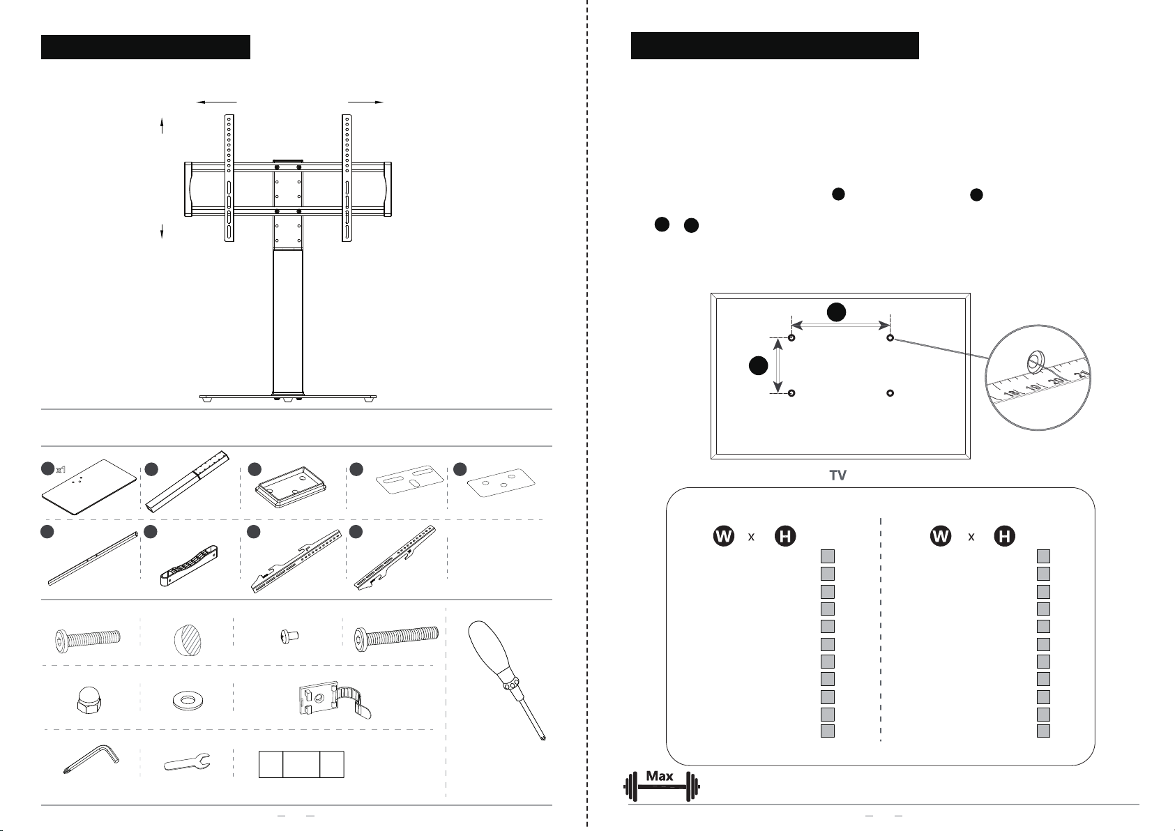
Please read this assembly manual carefully and make sure you have all the parts in the list
before you begin to install.
Meanwhile, please keep this assembly manual for future reference.
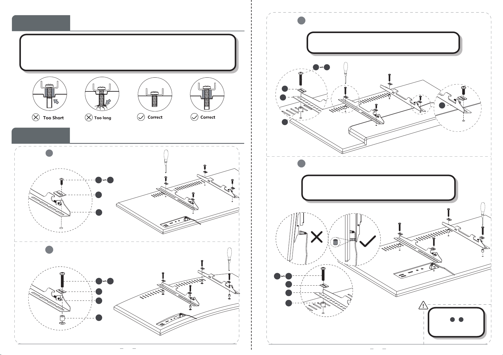
Please protect the furniture by placing all parts on a soft surface during assembly.
Please don't place very warm/cold objects on top of any surface, clean immediately with
microfiber cleaning cloths/towels if any liquids on the surface.
Never use multi-surface furniture polish spray or cleaner.
Do not touch the surface with a hard/acute object that may cause scratch or broken.
Do not allow children to climb onto the furniture.
Improper use or incorrect assembly may cause death or serious injury.
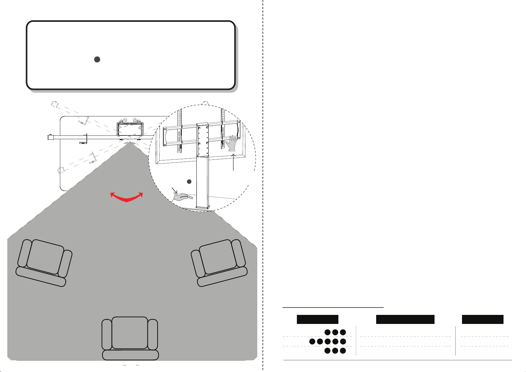
Use extra safety straps to ensure the best tip-over protection.
Do not use this product for any purpose or in any configuration not explicitly specified in
this instruction.
We hereby disclaim any liability for injury or damage arising from incorrect assembly,
incorrect mounting, or incorrect use of this product.
Order ID. -in your order details in online shopping platform.
Model No. - lower left corner on manual first page, or SKU no. in order details.
Series No. - lower right corner on manual first page.
01

x1 2x1 4x1 5x1
Tools Requried
(Not included)
PARTS LIST
6
x2
7
x2
8
x1
9
x1
E
1
x4 E
2
x4 Fx2
G
2
x1 S
Screws for TV
(5mm)
S1S6
...
3x1
Cx4 Dx4
G
1
x1
Bx5Ax3
02
PRODUCT DESCRIPTION
1
VESA:100-660mm
VESA:100-400mm
(steel washer)
(paper washer)
( plastic )
(13#)
Please check the weight of your display, it should be less than 133bs/ 60kgs.
Units:mm Units: inch
W
H
100
200
200
300
300
400
400
400
600
600
100
100
200
200
300
300
200
400
200
400
x
x
x
x
x
x
x
x
x
x
4.0
7.9
7.9
11.8
11.8
15.7
15.7
15.7
23.6
23.6
x
x
x
x
x
x
x
x
x
x
4.0
4.0
7.9
7.9
11.8
11.8
7.9
15.7
7.9
15.7
√
√
√
√
√
√
√
√
√
√
√
√
√
√
√
√
√
√
660 400
x25.9 x15.7
√ √
√
√
VESA standard of TV STAND
MEASURE VESA FOR YOUR TV
03
133lbs/60kgs
What does the VESA standard mean?
The VESA standard is a standard for attaching flat screens / LCD / monitors / televisions
to monitor mounts or TV mounts.
Prerequisite is that both the monitor / TV and the monitor mount have the same VESA
standard.
1、
2、
Look at the back of your TV/monitor for threaded holes.
Measure the horizontal distance Wand vertical distance H of the screw holes (center
to center).
W x Hshould comply with the VESA standard of TV stand listed in below sheet.
Notice: If the TV/monitor is not compatible with VESA, it can still be attached to the desired
bracket by using VESA Adapters(not included and should extra buy).

2、Fix part and part with screw .
1
Team Work
04
B
B
G1
A
C
x
1
x
1
A
B
x
3
x
1
x
1
x
1
x
1
x
5
GG
1
05
2
(paper washer)
(plastic)
(steel washer)
1
4
5
3
2
7
7
6
1
3
4
52
x2
x2
C
G
x4
x1
6
7
Tempered Glass
(Painting Side)
Face Down
2
3
1
Holes facing the same direction
G1
G
1
1、Install part and part with holes facing the same
direction.
6
6
7
7
C
Please do not fully tighten before screwing into the right
holes.

3
06
x
4
x
1
x
1
x
4
G
E
D
x
4
G
2
G
1
E
1
E
2
High Low
Levelling before
fixing the screws.
07
4
The round hole is on the top The round hole is on the top
G1
D
6
S5
S4S3S2S1
S6 8
x4
S0
x4 x4 x4 x4
x4 x1
9
x1
M4x30 M6x12 M6x35 M8x16 M8x50
89
Round holes
M6M4 M8
Select TV Screw Diameter
STEP 1
Please make sure the diameter of the screw S0-S4 are suitable for your TV.
The round hole is on the top .
The flat surface of part and part
should be mounted inward.
9
8
G2E1E2
9
8
Please do not fully tighten before screwing into the right
holes.

S5
S5
S6
S6
Option (For TV with A“Bump”)
3
Option (Potential Cable Blockage)
4
09
S0 S4
S0 S4
8
9
S0 S4
S5
S5
8
8
8
S6
Option (For Flat Back TV)
08
Select installation method according to TV
STEP 3
1
Option (For Round Back TV or Curved TV)
2
S0 S4
Please make sure the
brackets 、 are
vertically centered and
level with each other.
98
Select TV Screw Length
STEP 2
When attaching brackets to the TV, be careful not to over tighten screws
and be sure that screws don't bottom out in the mounting holes.
Please make sure the length of thread engagement at least 6 turns or
5/16 inch (8mm).
Spacers may be necessary for 2 holes ONLY.
Spacers may be necessary when cables or
plug/outlets are blocked by brackets.

11
Fx2x2
6
Cable management clips let you easily organization for power
and AV cords to keep neat.
F
10
5
e
Make sure the safety screw fully drive in after settle your
TV to thisstand .
e
F

1312
USERS GUIDELINE
TV plate -
3 levels optional for height adjustment
H
H
W
W
Back of TV
Back of TV
Stand Height Adjustment - Holes Selection of Brackets
When attaching brackets 、 to the TV, different holes selection of
brackets 、 will result different TV raise height as below diagrams
show.
98
98
Stand Height Adjustment - TV Plate
1、Please take off the TV from the stand then select the proper height
by yourself.
2、Each level adjustment distance for TV plate is 50 mm (2 inch).
3、Attach the TV to the TV plate again and tighten the safety screws
on the bottom of brackets to secure the TV to the stand.
e

14
:±25°
View Angle Adjustment
Notice - Swivel function is manual not automatic.
Base is not turntable.
TV plate can swivel left and right 25 degrees in each side to provide
you a wide-range viewing angles when watch the TV.
Please hold the base when you need to swivel TV plate.
1
Swivel
Step 2-
Swivel the plate
Step 1-
Hold the base 1
North America CA
MX
US 1 626 400 2997
(CST 8AM - 5PM Mon.-Fri. )
cs@rfiver.com
Asia JP CN IN jpcs@rfiver.com
Europe UK DE FR
IT
ES eucs@rfiver.com
CUSTOMER SERVICE SUPPORTS
CONTINENTS CONTACT DETAILS MAILBOX
This manual suits for next models
1
Table of contents
Other Rfiver TV Mount manuals