Page 6 User Guide: RFM5104/14 Predictive Maintenance System User Guide
IN012F13 www.RFMicron.com
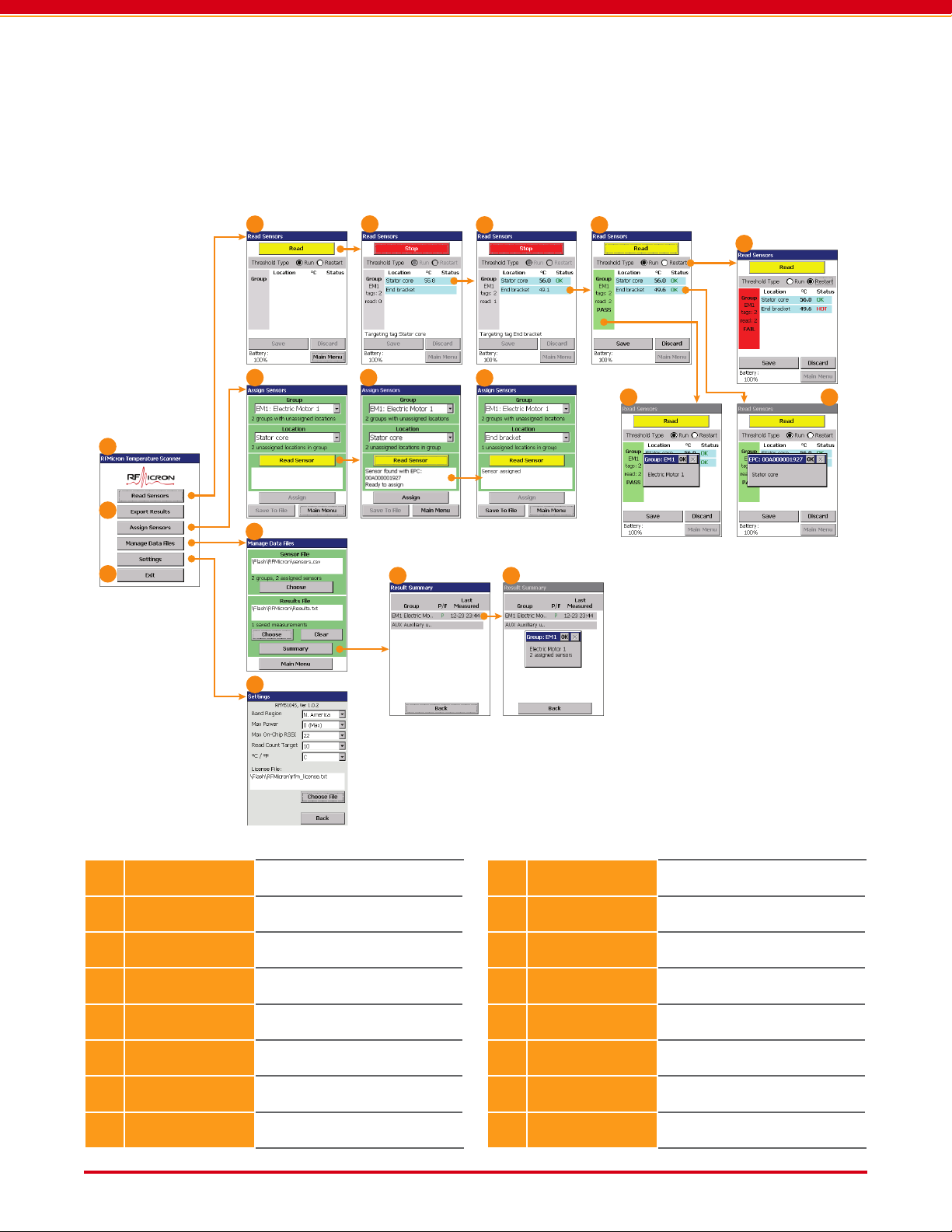
3. USING THE SYSTEM
3.1. Identifying and Organizing Sensors
RFMicron’s wireless, battery-free temperature
sensors are uniquely identiable by an Electronic
Product Code (EPC) stored in each sensor’s mem-
ory. Because the EPC does not, by itself, indicate
where the sensor is installed or what device it is
monitoring, each sensor must be registered and
assigned within the Temperature Scanner soft-
ware. A meaningful location description for each
installed sensor is very helpful.
Multiple sensors can be associated with each
other in groups. Sensor groups can be used to
organize sets of sensors by the equipment or
machine they are monitoring, or sensors can be
grouped according to which sensors are visible to
the reader from a particular reading location.
Sensor locations and group denitions are stored
in a text le called the SENSOR FILE. The SENSOR
FILE employs a comma-separated-value (CSV)
format and can be edited in a spreadsheet or
text editor application. For example, various
location and group descriptions can be added
to the original SENSOR FILE to speed the sensor
installation and assignment process.
When Temperature Scanner reads the EPC ID
code from a sensor, it uses the information in the
SENSOR FILE to display its location description
and group descriptions.
3.2. Temperature Thresholds
In addition to displaying the temperature re-
ported by installed sensors, Temperature Scan-
ner also compares the temperature to alarm
thresholds set by the user. When the measured
temperature of a sensor exceeds a threshold, a
warning is displayed on the screen, where the
sensor is shown as failing the temperature test.
Two thresholds are dened for each sensor.
These thresholds are named according to termi-
nology associated with electric motors but can
be used for any purpose by the user. The RUN
THRESHOLD is the temperature limit that the
motor or equipment should not exceed during
normal operation. The RESTART THRESHOLD is
typically a higher temperature limit that the
equipment can not exceed without risking ther-
mal damage to the equipment itself.
For motors, the RESTART THRESHOLD alarm is
calculated as the motor’s electrical insulation
thermal limit, minus the typical heat increase of
restarting that motor in that particular installa-
tion, minus 30 °C to 40 °C to account for the dif-
ference in temperature between the motor core
and the measurement point where the sensor
is located. The motor’s restart heating can be
measured by recording the motor’s temperature
increase immediately before stopping and then
after restarting the motor.
NOTE: If Run and Restart alarms don’t apply
to your application, feel free to treat these
as two independent alarm thresholds.
3.3. Preparing Sensors for Use
The rst step to using the Predictive Mainte-
nance System is to decide where sensors will be
installed, how sets of sensors will be grouped
together, and what their RUN THRESHOLD and
RESTART THRESHOLD should be. For example,
two sensors might be placed on a particular elec-
tric motor, one on the stator core and one on the
bearing cover to measure bearing temperature.
The stator sensor might have a RUN THRESHOLD
and a RESTART THRESHOLD of 55 and 90 °C, and
the bearing sensor might have a RUN THRESHOLD
and a RESTART THRESHOLD of 45 and 50 °C. Since
the two sensors are measuring dierent locations
on the same machine, they might be added to a
single group.