RGB Lasersystems Abeam User manual

User Manual

User Manual
For the Lambda beam with PowerController Laser
Version: 2.4.0
Date: December 20, 2020
This document is protected by copyright. Do not copy or publish this document or parts
of it without written permission of RGB Lasersystems GmbH .
Product specications and descriptions in this manual are subject to change without
notice. RGB Lasersystems GmbH will not be responsible for errors and omissions in this
manual or for direct or incidental damages in connection with the use of this device or
information.
© 2020 RGB Lasersystems GmbH
Donaupark 13
93309 Kelheim
Germany
Telephone: +49 9441 1750 33 – 0
Website: http://www.rgb-photonics.com
E-Mail: [email protected]

Contents
Contents i
1 Laser Safety Precautions 1
2 Introduction 3
2.1 Product Overview ................................. 3
2.2 Package Contents ................................. 4
3 Installation and Operation 5
3.1 Precautions .................................... 5
3.2 Device Setup ................................... 5
3.3 Laser operation .................................. 7
3.4 Operation modes ................................. 8
3.5 Disconnecting the system ............................ 8
3.6 Troubleshooting ................................. 9
4 Computer Control 11
4.1 Ltune Laser Control Software .......................... 11
4.2 Serial Communication .............................. 13
5 Specications 19
5.1 General Specications .............................. 19
5.2 Beam Specications ............................... 20
5.3 Electrical Specications ............................. 20
5.4 Mechanical specications ............................ 20
6 Optional system congurations 23
7 Certications and Compliance 25
i

1 Laser Safety Precautions
CAUTION: This device emits visible and invisible LASER ra-
diation. Avoid exposure to the beam!
Lasers emit visible and invisible radiation that may cause
damages to material and person, mainly by thermal eect.
Radiation entering the human eye can damage the retina,
which leads to partial or total loss of vision. The damage can
occur without particular perception or sensation of pain.
Please consider all protection and safety regulations
while handling laser systems. Always use laser protection glasses for the specied wave-
length range.
Never direct the laser towards people. Keep the laser beam away from reective sur-
faces in order to avoid uncontrolled reections. Do not mount the laser at eye level.
It is your responsibility to guarantee the laser safety as required by law. Please pay at-
tention to safety regulations DIN EN 61010-1, DIN EN 60825-1:2003-10 and DIN EN 60950
when operating the laser.
The Lambda mini series is specied by the United States Na-
tional Center of Device and Radiological Health (CDRH)) as a class
3b laser product. Visible and invisible laser radiation is emitted.
Modications that my aect any aspect of the product’s per-
formance or intended functions will require re-certication and
re-identication of the product in accordance with the provi-
sions of 21CFR 1040.10 and 1040.11.
Lambda mini laser modules are marked with a warning label
as show on the right.
1


2 Introduction
2.1 Product Overview
The Lambda beam series oers high performance, modulatable laser modules in a small
design. The high quality product„Made in Germany“guarantees universal capabilities in
almost all elds of applications, with optical output powers up to 1000 mW. High durabil-
ity, excellent beam quality and various options for system integration (for example into
the Qioptiq rail system FLS 40) guarantee highest exibility in industrial, scientic and
medical applications.
Laser Head Features
• Small design
• Optical output powers up to 1000 mW
• Active Temperature Stabilization
• IP67 protected housing, optionally vacuum sealed
• Optional ber coupler
• Horizontal, vertical and diagonal mounting options
• Produced in clean-room atmosphere
• Adjustable temperature
• Professional housing
Laser Controller Features
• Compact design
• Microprocessor-controlled laser driver
• Digital control via Universal Serial Bus (USB)
• Modulation input analog or digital 0 V to 5 V direct current (DC)
• Interlock input, key switch and mode switch
3

CHAPTER 2. INTRODUCTION Lambda beam user manual
2.2 Package Contents
Laser head
In order to provide the best beam quality only high
quality optical components are used within the
laser head. A thermoelectric cooler is integrated for
stabilizing the temperature.
Laser controller
The laser controller includes three status indica-
tors, a USB interface, a modulation mode switch
and a key switch with a 5 s delay. The back
side holds connectors for the laser head (D-
Subminiature 9 (DSUB-9)), modulation input (BNC),
interlock and power supply.
AC adapter
The alternating current (AC) adapter provides a
regulated power supply from any AC outlet (100 V
to 240 V). Only use the AC adapter included with
your laser, otherwise damage to the laser system
may occur.
Cable
The Lambda beam system includes a 0.8 m DSUB-9
cable to connect the laser head to the controller as well as a standard 1.5 m Micro USB
cable to connect the controller to a computer.
Software
The CD-ROM includes the Windows application software Ltune for conguring and con-
trolling the laser system as well as this manual as a Portable Document Format (PDF) le.
4

3 Installation and Operation
3.1 Precautions
•Take care of all laser safety instructions as described in chapter 1. Always wear laser
protection glasses for the specied wavelength range.
• Consider regulations for electrostatic discharge (ESD).
• Do not open the laser head. Opening the case voids the warranty and may cause
uncontrolled laser radiation.
• Always mount the laser module securely and pay attention to sucient heat dissipa-
tion.
•Never disconnect the laser head from the controller while connected to the power
supply. This can damage the laser.
•Do not reect the laser beam back into the laser head. The laser diode could be
damaged if more than 2%of the emitted power is reected back into it. Carefully
check all mirroring surfaces of your optical setup for possible back reections. If re-
quired, use a suitable optical insulator.
• Do not exceed the environment conditions specied in chapter 5.
3.2 Device Setup
1. Make sure the key switch is in the OFF position.
2. Connect the Lambda beam laser controller with the laser head using the accompa-
nying cable.
3. If you have several laser modules, please note that the controllers are not inter-
changeable. Make sure the serial numbers on the laser head and the laser controller
match each other.
4. Connect the AC adapter to the laser controller.
5. Turn on the supply voltage VCC.
6. After a quick self-test the green POWER LED should be lit continuously. The status
indicators are further described in the following section.
5

CHAPTER 3. INSTALLATION AND OPERATION Lambda beam user manual
Connector and Controls
The PowerController laser driver has the following connectors and controls:
(a) controller front side
(b) controller back side
1Micro USB connector
2Key switch
3Laser head connector (DSUB-9)
4Modulation mode switch (CW,TTL, Analog)
5Interlock connector
6Power supply input (DC 12 V)
7Modulation input (Bayonet Neill-Concelman (BNC))
6

Lambda beam user manual 3.3. LASER OPERATION
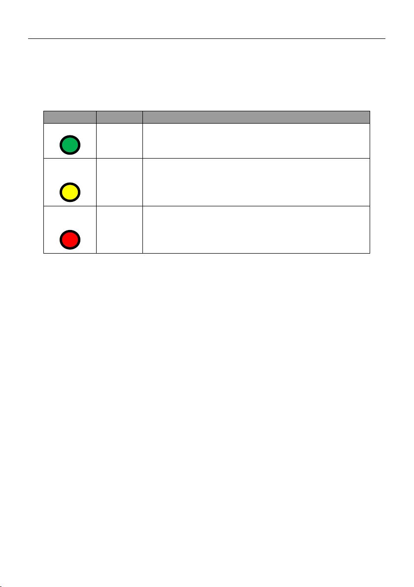
Status Indicators
The laser module includes two light emitting diodes (LEDs) to indicate the laser status:
LED Status Description
POWER On
O
Key switch o, interlock open or switched o via USB
Power supply not connected
KEYLOCK On Key switch o, interlock open or switched o via USB
O Key switch on and interlock closed (and switched on
via USB if connected to computer)
Flashing Error
EMISSION On Laser active, emission possible
(depending on selected output power)
O Laser inactive
Flashing 5 second delay before activating laser
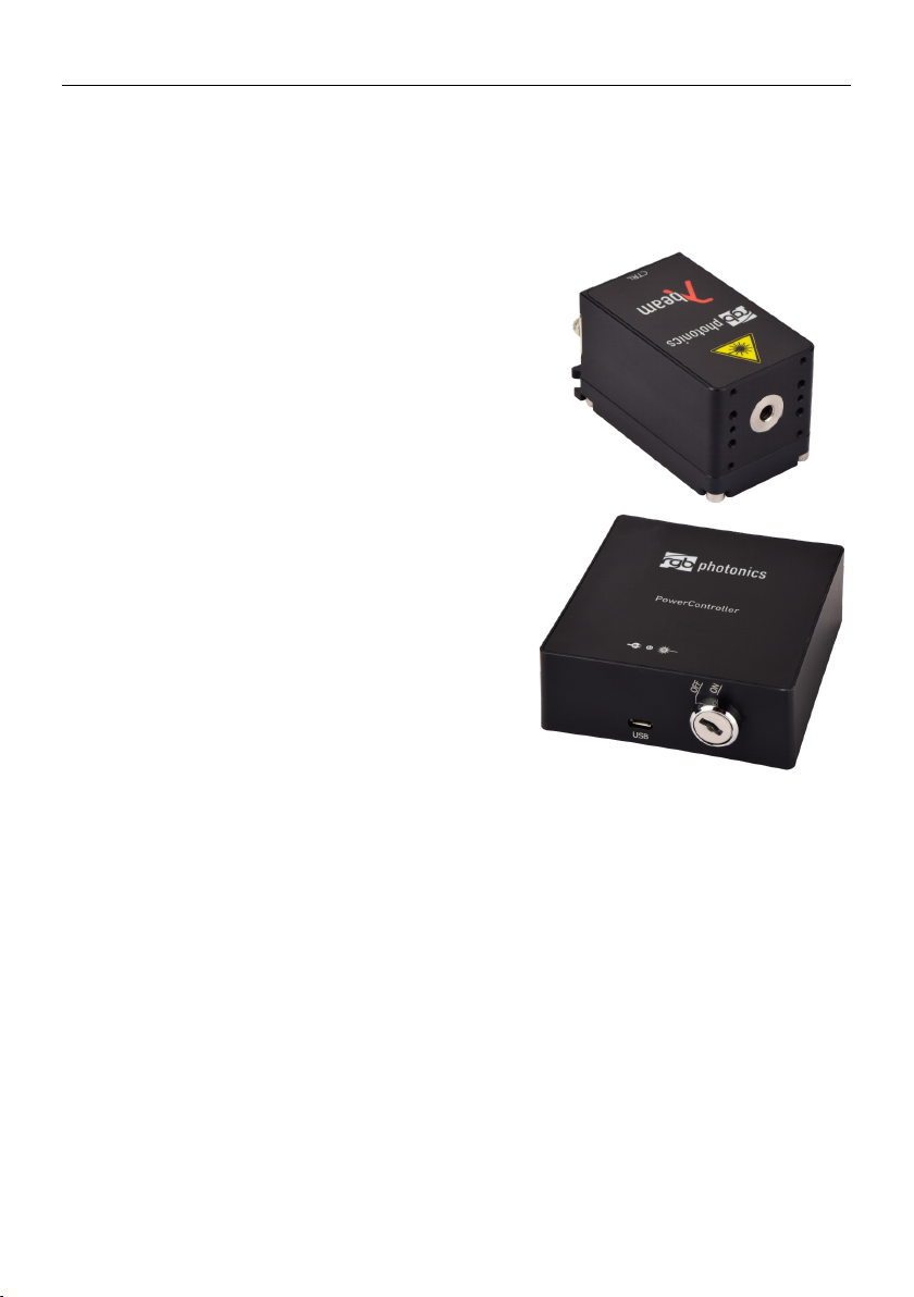
3.3 Laser operation
In order to turn the laser on without using a computer or remote control, please:
1. Connect the system as described in the previous section.
2. Select the modulation mode using the switch (continuous wave (CW) /transistor-
transistor logic (TTL) / ANALOG) on the back side of the controller. Changing the
modulation mode is only possible while the key switch is in the OFF position.
3. For TTL or ANALOG modulation mode, please apply a voltage to the modulation
input (BNC connector). Note that even with an input voltage of 0 V, a small amount
of laser radiation can be emitted.
4. Close the interlock and turn the key switch to the ON position. The laser will start
with a 5 s delay (as required by CDRH regulation ). Once the laser is active, the EMIS-
SION indicator is lit.
For safety reasons, the key lock is activated when you connect the laser to power, even
if the key switch is in the ON position. To start the laser, turn the key switch o and on
again.
The Lambda beam series can also be controlled via USB as described in chapter 4.
7

CHAPTER 3. INSTALLATION AND OPERATION Lambda beam user manual
Note for lasers at 473 nm,532 nm and 561 nm:it is recommended to initially oper-
ate the laser at full maximum output power for 5 min. Afterwards the output power can
be adjusted to any value. At low output powers these lasers often exhibit multi-mode
emission.
3.4 Operation modes
You can select the operation mode using Ltune or your own custom software. In stand-
alone operation, the laser system is always in Combined Modulation Mode. The technical
specications for the modulation inputs can be found in chapter 5.
Constant Power Mode
The Lambda beam laser systems can be driven in CW mode without an external control
voltage. In this case, the laser emission is constant at the value which is dened by the
Ltune Software.
Analog Modulation Mode
In this mode the optical output power can be controlled by an external voltage at the
analog modulation input connector. The output power is modulated proportional to this
signal.
Digital Modulation Mode
Here, the digital modulation input is used to switch the laser o and on between 0%
and 100 %maximum power. The nominal TTL input levels for the low-speed modulation
input are 0 V (laser o ) and 5 V (laser on)1.
3.5 Disconnecting the system
Always disconnect the power supply before removing the controller from the laser head
in order to prevent damage to the laser!
To disconnect the laser system, please proceed in this order:
1. Turn the key switch to the OFF position.
2. Disconnect the power supply and the modulation input connector (if used) from
the controller.
1However, all signals below 0.8 V are considered as o and above 2 V as on.
8

Lambda beam user manual 3.6. TROUBLESHOOTING
3. Finally disconnect the laser head from the controller.
3.6 Troubleshooting
If the device is detected by Ltune, but there is no laser emission:
Please make sure that these conditions are met:
• The green LED is lit continuously (if not, please check the bottom of the Ltune window
for error messages).
• The interlock connector is closed
• The key switch is set to the ON position
• Either Constant Power Mode is selected or a proper signal is connected to the mod-
ulation inputs
• If connected to a computer: The power on/o button in Ltune is turned on and an
output power larger than zero is selected
If the yellow LED is ashing, please run Ltune and check the bottom of the window for
error messages.
If the device is not detected when Ltune is started
First of all, please disconnect the laser from the computer, restart the computer, connect
the laser again and start the Ltune software.
If the laser is still not found: The Ltune software communicates with the laser using a
”virtual serial port”. If the driver is installed correctly, it should show up in the Windows
Device Manager. You can open the device manager by clicking Start -> Control Panel (->
Performance and Maintenance) -> System -> Hardware -> Device Manager.
In the device manager, please open the ”Ports (COM & LPT)”subtree. One of the COM
ports listed there should belong to your laser. If you right-click on the correct item, choose
”Properties” and then the ”Driver” tab page, it should read: ”Driver Provider: FTDI” and
”Driver Version: 2.8.14.0” (or later). If this is the case, please start Ltune and try to select
this COM port manually by unchecking ”Auto-scan all serial ports” in ”Device setup”.
If your laser is not listed in the device manager or marked with an exclamation or
question mark, please try the following:
1. Disconnect your laser from the computer and from power supply.
2. Download http://www.ftdichip.com/Resources/Utilities/FTClean.zip and run this tool
to remove the FTDI driver from your computer.
9

CHAPTER 3. INSTALLATION AND OPERATION Lambda beam user manual
3. Reinstall Ltune from the CD.
4. Reconnect the laser to the computer.
5. Start Ltune.
10

4 Computer Control
The Lambda mini uses a USB interface for remote control. The laser can be controlled
with
• The Windows application software Ltune (included),
• the cable remote control RC-1 (available separately) or
• Custom user software via serial communication.
4.1 Ltune Laser Control Software
The Lambda beam laser can be congured and controlled using the Ltune software for
Windows. The software features:
• Modulation mode selection
• Output power adjustment
• Display of the laser status, conguration and operating hours
• Temperature display and adjustment
To install the software, simply run the setup le from the CD-ROM included in the
package. The setup package then installs the application software and the device driver.
For the operating system to properly recognize the de software rst before attaching the
device.
The software is tested with 32 and 64 bit versions of Windows 10, 8, 7, Vista and XP.
It requires the Microsoft .NET framework version 3.5 or 4.0, which is already installed on
most PCs. If this framework is not installed, the setup package asks you to install it rst.
You can nd the setup le for the .NET framework on the CD or download it from Mi-
crosoft’s website. Please note that you need at least version 3.5 of the .NET framework.
After the software is installed, please connect your Lambda mini laser to a USB 2.0
port on the computer. You can use the provided USB cable or almost any other Micro-
USB cable.
If not already installed wait until the laser driver is completely installed. The laser
should be detected automatically. If not you can click on device setup to start a new
search.
11

CHAPTER 4. COMPUTER CONTROL Lambda beam user manual
Figure 4.1: Ltunes GUI
Please note that you can change the user interface to a more compact view by clicking
the small button next to ”Device Proporties”
The sliders for“Repetition time” and “Pulse width” are for future enhancements.
The “Temperature” slider can be used to shift the working temperature of the laser.
This can be used to shift the wavelength in a certain amount but also has eects on the
output power.
12

Lambda beam user manual 4.2. SERIAL COMMUNICATION
4.2 Serial Communication
Overview
When the laser controller is connected to a PC and the device driver installed, it shows
up as a virtual communication port/serial port (COM) port and can be accessed from al-
most any programming language. A detailed description of the commands and queries
is given in the following section.
The command settings are not stored when the system is powered down.
Communication protocol
The commands and queries have the following syntax:
Commands: command=<parameter value>
A command changes an actual setting. The syntax is the command, followed by an equal
sign and the parameter value. The parameter value is the value to be set. Commands
have no return value.
Queries: query?
A query returns information about the device or the value of a setting. The syntax is the
query, followed by a question mark. Queries have no parameter value. A query delivers
a return value.
Return Code
A return code gives information about the processing of a command or query. There is
always a space character between the return code and the result. The return codes are
listet in table 4.1.
Table 4.1: Return Codes
Code Name Description
0 COMMAND_SUCCESS Command successful
1 COMMAND_INVALID Command invalid
2 PARAMETER_ERROR Wrong numbers of parameters
3 VALUE_INVALID Parameter value is out of range
4 CODE_INVALID Unlocking code is wrong
5 DEVICE_LOCKED Device is locked for this command
6 FUNCTION_NOT_SUPPORTED This function is not supported
7 COM_TIME_OUT Timeout while reading command (60 s)
8 VALUE_NOT_AVAILABLE This value is currently not available
13

CHAPTER 4. COMPUTER CONTROL Lambda beam user manual
All commands and queries and all responses from the device are followed by the line
termination string ”\r \n” (carriage return & line feed). All instructions have to be written
in capital letters.
Initializing the serial communication
The Lambda mini uses the communication settings displayed in table 4.2.
Table 4.2: Lambda mini communication settings
Baud rate 57600
Parity None
Data bits 8
Stop bits 1
To initialize the controller, send “INIT”. The controller responds with the return code
0 (Command successful).
Closing the communication
Send “BYE” to close the connection to the laser controller.
Turning the laser on and o
This command is used to set the and read the ”Laser Enable” request. The laser can only
be activated if the key switch is in the ON position and the interlock is closed.
Table 4.3: Laser Enable commands
Command/
Query Parameter value Return code Return value
O= 0: Delete Enable Request
1: Set Enable Request
COMMAND_SUCCESS
PARAMETER_ERROR -
O? - COMMAND_SUCCESS 0: Enable Request not set
1: Enable Request set
Temperature settings2
The Lambda beam monitors the operating temperature. If it exceeds the permitted tem-
perature range, the laser is turned o to prevent damage to the module. The commands
for temperature settings are listed in table 4.4
2Not all laser systems support this function
14

Lambda beam user manual 4.2. SERIAL COMMUNICATION
Table 4.4: commands for temperature settings
Command/
Query Parameter value Return code Return value
T? -COMMAND_SUCCESS
VALUE_NOT_AVAILABLE Current temperature in °C
TD? - COMMAND_SUCCESS Default temperature in °C
T0= Temperature oset in °C
(vallue between LTN and LTP)
COMMAND_SUCCESS
VALUE_INVALID
FUNCTION_NOT_SUPPORTED
-
T0? - COMMAND_SUCCESS Temperature oset in °C
LTN? - COMMAND_SUCCESS Lowest operating
temperature in °C
LTP? - COMMAND_SUCCESS Highest operating
temperature in °C
The command TO= expects a temperature oset for the default temperature (TD?) to
be decreased or increased. The temperature can be adjusted with a resolution of 0.1∘C.
The highest and lowest possible temperature value can be queried with LTP? and
LTN?, respectively.
Selection of modulation mode
The following commands are used to change the mode of modulation. The mode se-
lection via USB takes priority over the manual switch on the laser controller. The actual
position of the manual switch can be determined with the SP? query.
Table 4.5: commands for selection of modulation mode
Command/
Query Parameter value Return code Return value
M=
A = external analog
T = external TTL
C = internal CW
M = combined analog & TTL
COMMAND_SUCCESS
VALUE_INVALID
FUNCTION_NOT_SUPPORTED
-
M- COMMAND_SUCCESS
A = external analog
T = external TTL
C = internal CW
M = combined analog & TTL
CW mode
The Lambda beam series can be operated in CW mode at constant power between 0%
and 100 %of the maximum output power. There is no need to supply an external control
voltage.
15

CHAPTER 4. COMPUTER CONTROL Lambda beam user manual
Table 4.6: CW mode commands
Command/
Query Parameter value Return code Return value
P? - COMMAND_SUCCESS Output power in mW
P= Output power in mW
(value between 0 and LP)
COMMAND_SUCCESS
VALUE_INVALID -
LP? - COMMAND_SUCCESS Maximum output power in mW
TTL modulation
In the TTL modulate mode the output power can be switched between two levels by
applying a TTL compatible (0 V and 5 V) external control voltage. The lower level is set by
the PO= command and the higher level by P=. If a level larger than the maximum output
power is specied for P= or a level larger than the P= value is specied for PO=, the value
is decreased to the maximum value.
Command/
Query Parameter value Return code Return value
PO? - COMMAND_SUCCESS Lower,Output level in mW
PO= Lower,Output level in mW
(value between 0 and P)
COMMAND_SUCCESS,
VALUE_INVALID -
Status and device information
The query S? gets the actual status of the laser system including information about the
Enable Request, the key switch, the interlock, active errors and the temperature control.
The query R? returns the operation hours of the laser system. The operation time is
the accumulated time during which the laser was active (red LED on).
16

Lambda beam user manual 4.2. SERIAL COMMUNICATION
Table 4.7: Status and device information commands
Query Parameter value Return code Returnvalue
S? - COMMAND_SUCCESS Current device status (see table below)
R? - COMMAND_SUCCESS Total operating hours [hhhh:mm]
DM? - COMMAND_SUCCESS Manufacturer
DT? - COMMAND_SUCCESS Device name
DS? - COMMAND_SUCCESS Serial number
DO? - COMMAND_SUCCESS Software version
DW? - COMMAND_SUCCESS Emission wavelength in nm
DF? - COMMAND_SUCCESS
Available features:
T = Temperature adjustable
H = High speed TTL integrated
D = Drive mode changeable (ACC/APC)
C = Temperature is controlled
M = External analog and digital modulation
A = Modulation inputs can be combined
R = Round beam
L = Wavelock
E = ECDL laser
W = Water-cooled
B = Multi-mode beam
S = Customized
DC? - COMMAND_SUCCESS ACC = active current control (ACC)
APC = active Power control (APC)
The result of the status request S? is a bit-wise combination of the values listed in
table 4.8
Table 4.8: status request commands
Code Mnemonic Description
0x01 LASER_ON Laser system in active, radiation can be emitted
0x02 (reserved)
0x04 INTERLOCK_OPEN The interlock is open
0x08 ERROR Error is active (error can be read with E? query)
0x10 TEMPERATURE_OK Temperature of laser head is ok
Error status of the laser system
The query E? reads the actual active errors of the laser system.
Table 4.9: Error status of the laser system
Query Parameter value Return code Return value
E? - COMMAND_SUCCESS Error code (see table below)
Possible error codes are shown in table 4.10
17
Table of contents
Popular Lighting Equipment manuals by other brands

Professional Pool Products
Professional Pool Products RC04 instruction manual

B.K.Licht
B.K.Licht BKL1262 Mounting instructions

Cameo
Cameo PIXBAR DTW PRO user manual

Clas Ohlson
Clas Ohlson Seahorse 38-4256 manual

Honeywell
Honeywell ExiLED 290142 quick start guide

JB Systems
JB Systems LED PINSPOT Operation manual