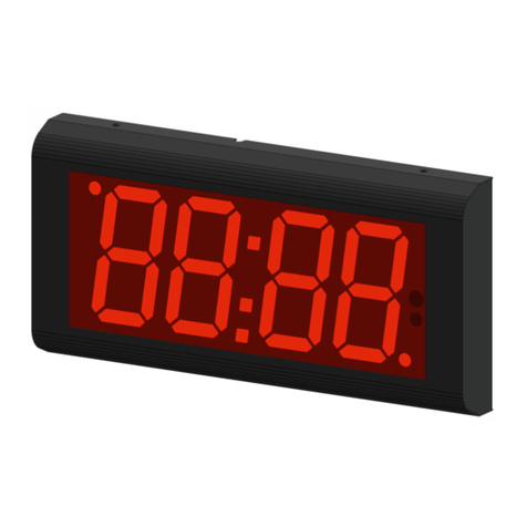
RGB Technology Kazel RM-470 User manual

OPERATION AND MAINTENANCE MANUAL
RM-470
Product code:
314-05-01
* Explanatory figure
OPERATION AND MAINTENANCE MANUAL
RM-470
Product code:
314-05-01

2 DTR_314-05-01-001_EN_a
Table of contents:
1. Specification ........................................................................................................................................ 3
2. Transport and storage......................................................................................................................... 3
3. Device construction............................................................................................................................. 3
3.1 RM-470 construction ................................................................................................................... 3
3.2 RM-470 dimensions ..................................................................................................................... 4
3.2.1 Dimensions without accessories .......................................................................................... 4
4. Device installation ............................................................................................................................... 4
4.1 RM-470 application...................................................................................................................... 4
4.2 "Autolearn” function.................................................................................................................... 4
4.3 RM-470 manual configuration (Communication protocol selection).......................................... 5
4.3.1 Embedded user menu (microswitch) ................................................................................... 5
4.3.2 Supported parameters and baud rates ................................................................................ 6
4.3.3 RGB WagSet 2 software........................................................................................................ 6
4.3.4 Web-panel ............................................................................................................................ 7
5. Display controller board...................................................................................................................... 7
5.1 Connectors and buttons on the controller board........................................................................ 7
5.2 List of connectors of the display controller board....................................................................... 8
5.2.1 RS-232 connector.................................................................................................................. 9
5.2.2 RS-485 / RS-422 connector................................................................................................... 9
5.2.3 0/20mA digital current loop ................................................................................................. 9
5.2.4 RJ-45 connector (Ethernet)................................................................................................... 9
6. Additional accessories......................................................................................................................... 9
6.1 RM-470 Visor................................................................................................................................ 9
6.2 Mounting rails............................................................................................................................ 10
6.3 Mounting brackets..................................................................................................................... 10
7. Automatic brightness control of the remote display........................................................................ 11
8. Initial start-up.................................................................................................................................... 11
9. Disposal and recycling ....................................................................................................................... 11
9.1 Packaging material recycling...................................................................................................... 11
9.2 Device disposal........................................................................................................................... 11
10. Most common installation errors...................................................................................................... 11

DTR_314-05-01-001_EN_a 3
1. Specification
RM-470 remote display
Dimensions: 1
679mm x 242mm x 74mm / 26.7in x 9.5in x 2.9in
Digit height:
120mm / 4.7in
Accepted input voltage range (long-term):
100 ÷ 240 VAC
Accepted input voltage range (short-term):
85 ÷ 264 VAC
Accepted input voltage range:
47 ÷ 63 Hz
Operating temperature (ambient):
-25°C ÷ 45°C / -13°F ÷ 113°F
Operating temperature (device surface):
-25°C ÷ 70°C / -13°F ÷ 158°F
Average power consumption:
7W
Ingress protection rating2:
IP 65 / NEMA 4
Device weight:
5kg / 11lbs
2. Transport and storage
The device is sensitive to mechanical damage. It should be ensured that it is properly secured for transport so as
to avoid any damage caused during transportation. It is forbidden to transport the device components
separately in a collective package –each item must be packed individually and cannot hit one another during
transportation.
The device should be stored in the temperature of -20°C to +60°C, at the humidity below 99% RH due to the
protective packaging.
3. Device construction
RM-470 is manufactured in a powder-coated steel housing. The properly installed device is characterised by
tightness class IP65.
3.1 RM-470 construction
The figure shows the RM-470 remote display construction3.
det. A –annuciators; det. B –screen; det. C –sliding drawer with controller board; det. D –drawer fixing screw; det. E –device front; det.
F–mounting bracket; det. G –fixing screw; det. H –brightness sensor;
Fig. 1
1Dimensions without accessories,
2Ingress protection rating according to EN 60529 standard,
3Explanatory figure

4 DTR_314-05-01-001_EN_a
3.2 RM-470 dimensions
3.2.1 Dimensions without accessories
Fig. 2
4. Device installation
The device should be mounted on a flat surface, with the wires facing down. Only the correct installation of the
device ensures its proper operation and the maintenance of the device parameters, such as housing tightness to
the declared IP class.
NOTICE!
Before any installation or maintenance operations, refer to the manual supplied by the manufacturer. Improper
connection to the mains power supply, incautious device installation, or improper use may cause property
damage, loss of health or death from an electric shock! In addition, failure to comply with the manufacturer's
instructions may void the warranty.
NOTICE!
It is forbidden to make any additional mounting points or any holes in the device components.
4.1 RM-470 application
RM-470 is designed to display measurement results transmitted by weighing terminals. The displays operate in
the automatic mode by default (see 4.2 "Autolearn”) and, in typical cases, they do not require prior
configuration. In special situations, it may be necessary to adjust the settings using RGB WagSet 2 software or
the Web-panel or through the user menu embedded in the device.
4.2 "Autolearn” function
The “Autolearn”mode is enabled by default (position #0 is set in the "proto" submenu). To disable it, the
communication protocol should be selected manually using the embedded user menu or RGB WagSet 2
software or the Web-panel. When this mode is active, at each start-up, the device detects the parameters of
communication with the weighing terminal and analyses the structure of the data frames which are sent to it. It
then adjusts its settings to allow proper communication with the terminal. The whole operation lasts a few
seconds, depending on the baud rate and time intervals between the consecutive frames. All communication
interfaces are supported, i.e. RS-232, RS-485/RS-422, 0/20mA digital current loop and the Ethernet.
The "Autolearn" procedure steps and their signalling are as follows:
1. Baud rate detection - dot 1 is flashing on the display,
2. Baud rate verification - dot 1 is solid, dot 2 is flashing,
3. Analysis of the protocol and its frame structure - dots 1 and 2 are solid, dot 3 is flashing.
During the analysis of the protocol and its frame structure, the measurement unit is also recognised, if sent by
indicator. The following tags are recognised - "kg" 'k' 'K' "tn" "TN" " t" 'T' 't' "LB" "lb" 'L' 'l' "OZ" "oz" 'o' 'O'. In
case the indicator does not send units or sends units that are not recognised by the “Autolearn”function, the
default unit will be set. Depending on the purchased regional version, it is "kg" or "lb".

DTR_314-05-01-001_EN_a 5
The “Autolearn”function also detects gross/net measurements if the following markers are sent in the frame:
- for the Net measurement: 'n' and 'N' from the ASCII table,
- for the Gross measurement: 'g' and 'G' from the ASCII table.
In this case, the marker position will also be saved. If, during the operation of the device, the transmitted
measurement marker changes, e.g. from "n" to "g", the indicator will change accordingly.
The “Autolearn”function supports the following transmission parameters:
Baud rate:
2400, 4800, 9600, 19200
Transmission parameters (data bits, parity, stop
bits): 8N1, 7E1, 7O1
8N1, 7E1, 7O1
Table 1
4.3 RM-470 manual configuration (Communication protocol selection)
4.3.1 Embedded user menu (microswitch)
The user menu embedded in the device allows to select the communication protocol, display the information
about the software version, reset to the default settings. The "B1" microswitch, used to operate the menu,
is located inside the display, and is accessible after unscrewing two screws M4x10 (Fig. 3, det. A) and after
pulling out the drawer as indicated by the black arrow. The microswitch is located on the controller board as
illustrated below (Fig. 3, det. B). There is no need to open the external covers.
det. A –Screw M4x10; det. B –microswitch
Fig. 3
The user menu is called up by pressing and holding down the "B1" microswitch and releasing it
when the desired option is displayed. Regardless the option, you can exit the user menu by pressing the
microbutton and releasing it when switching between the options (while switching between the options, the
display is not displaying any information)
The user menu has the following options:
1) info - This option allows you to display the software version. For displays with the Ethernet interface,
network layer settings are also provided (IP address, network mask, communication port for RGB WagSet 2
software and communication port for the weighing indicator). Exiting the "info" submenu happens
automatically after displaying the information.

6 DTR_314-05-01-001_EN_a
2) proto - This option enables the selection of the communication protocol saved in the display memory,
which enables cooperation with the selected weighing indicator. The protocol is changed by pressing the
microbutton. Saving the selected protocol is accomplished by long holding down the microbutton (until the
message "Saved" appears). Exiting the "proto" submenu comes after 30 seconds of the user inactivity.
3) custm –The "custm" option allows you to select the dedicated communication protocol to work with the
weighing indicators of selected clients. The protocols have special custom settings required by the given
client. Setting the protocol is done in the same way as in the case of the "proto" option - saving the
selected protocol is accomplished by long holding down the microbutton (until the message "Saved"
appears), while exiting the "custm" submenu comes automatically after 30 seconds of the user inactivity.
4) reset - This option allows you to reset the default remote display protocol and to activate the “Autolearn”
mode. In addition, in the devices with the Ethernet interface, you can restore the default network layer
settings (IP address: 192.168.0.11, network mask: 255.255.255.0, communication port for RGB WagSet 2
software: 2101 and communication port for the weighing terminal: 2102). To restore the default settings
you should, during the normal operation of the device, press the microbutton and hold it down until the
message "reset" appears. Hold the button down until the message "reset" starts blinking and do not
release it until the message "default" is displayed. Releasing the button before the message "default"
appears will result in interrupting the process of restoring the default settings and the display will continue
working according to the previously programmed parameters. Defining new network settings is possible
through the embedded Web-panel or by using RGB WagSet 2 software available at www.kazel-
displays.com.
4.3.2 Supported parameters and baud rates
Interface
Transmission parameters
Communication speed
RS232, RS485, RS422, CL
Data bits: 7, Parity: Odd, Even
Data bits: 8, Parity: None, Odd, Even
Stop bits: 1
300, 600, 1200, 2400, 4800, 9600,
14400, 19200, 28800, 38400, 57600,
76800, 115200, 230400
Table 2
4.3.3 RGB WagSet 2 software
Using WagSet 2 software, you can perform advanced configuration of the device. The software enables
changing:
- parameters of displaying the weighing result,
- entering and editing advertising text,
- response of the display to special situations (e.g. overload, underload, instability, etc.),
The detailed information concerning the configuration via your computer can be found in the manual supplied
with RGB WagSet 2 software.
DTR_314-05-01-001_EN_a 7
4.3.4 Web-panel
The embedded Web panel allows:
- selecting the communication protocol of the weighing indicator,
- changing the network settings,
- checking the version of and updating the display software,
The detailed information concerning the Web-panel operation and its capabilities can be found in the device
operation manual.
5. Display controller board
The controller board is responsible for processing and displaying the weighing result incoming from the
weighing indicator.
5.1 Connectors and buttons on the controller board
det. A –LED module connector; det. B –brightness sensor connector; det. C –RS-485/RS-422 connector; det. D –0/20mA digital current
loop; det. E –RS-232 connector; det. F –RS isolated interface connector; det. G –microswitch (B1, B2, B3); det. H –mains power supply
connector; det. I –radioline connector; det. J –controller power supply [5V]; det. K –Ethernet connector; det. L –status LEDs (D1 wired
data transmission).
Fig. 4

8 DTR_314-05-01-001_EN_a
5.2 List of connectors of the display controller board
Table 3 lists the controller connectors (Fig. 5, det. B) in RM-470 remote display. The connectors can be accessed
by pulling out the controller board drawer, without opening the entire device, or removing any connections or
parts. LED modules (Fig. 5, det. D) are fixed to the back cover (Fig. 5, det. C).
det. A –device front; det. B –controller; det. C –back cover; det. D –LED modules
Fig. 5
NOTICE!
The housing should be disassembled only when the power supply is disconnected.
STANDARD4
Interface / Function
Connector
markings
Notes
RS-232
RA
The RXD line of the RS-232 interface should be connected
with the weighing indicator TXD output
RK
GND line of the RS-232 interface
0/20mA (CL) digital
current loop
CA
CL line of the current loop. The line should be connected with
the weighing indicator TXD output
CK
GND line of the current loop interface
RS-485 RS-422
A
RS-485 and RS-422 interface non-inverting line
B
RS-485 and RS-422 interface inverting line
GND
GND line of the RS-485 and RS-422 interfaces for use at risk of
a significant difference in the potentials of the display mass
and the weighing indicator mass
Ethernet
ETH
RJ-45 socket
Table 1
4All connectors are available as standard on the PCB controller.

DTR_314-05-01-001_EN_a 9
5.2.1 RS-232 connector
For configuration purposes, the user connects the remote display to the computer with installed RGB WagSet 2
software via RS-232 connector.
5.2.2 RS-485 / RS-422 connector
For configuration purposes, the user connects the remote display to the computer with installed RGB WagSet 2
software via RS-485 / RS-422 connector.
5.2.3 0/20mA digital current loop
For configuration purposes, the user connects the remote display to the computer with installed RGB WagSet 2
software via digital current loop connector.
5.2.4 RJ-45 connector (Ethernet)
For configuration purposes, the user connects the remote display to the computer with installed RGB WagSet 2
software via the RJ-45 connector. This connection can also be used to access the Web-panel configuration.
6. Additional accessories
6.1 RM-470 Visor
Fig. 6
Fig. 7

10 DTR_314-05-01-001_EN_a
6.2 Mounting rails
Fig. 8
Fig. 9
6.3 Mounting brackets
Fig. 10
Pole mounting brackets are available in the following sizes:
2" - pole outer diameter 60.3 mm,
3" - pole outer diameter 84.0 –88.9 mm,
4" - pole outer diameter 111.1 –115.3 mm,
5" - pole outer diameter 139.7 –146.1 mm.

DTR_314-05-01-001_EN_a 11
7. Automatic brightness control of the remote display
RM-470 has a brightness sensor installed on the LED panel as standard. When the automatic control profile is
enabled, the device adjusts its brightness responsively to the intensity of daylight.
det. A –brightness sensor
Fig. 11
8. Initial start-up
Step 1: Make sure that all cables are properly connected,
Step 2: Make sure that all components have been installed in the correct orientation,
Step 3: Connect the device to the mains power supply,
Step 4: The properly connected display will show moving arrows (> >> >>>), followed by a hard space symbol (_)
in the bottom right corner. It means that the user has 7 seconds to send the configuration to the remote
display. If no configuration is sent to the device, it will launch the "Autolearn" process.
9. Disposal and recycling
9.1 Packaging material recycling
The packaging elements must be segregated and recycled in accordance with the local waste disposal
regulations.
9.2 Device disposal
The device must not be disposed of with normal municipal waste! In accordance with Directive 2012/19/EU
(WEEE), the user is obliged to deliver the damaged or destroyed device to the appropriate disposal facility if
there is no economically justified repair possibility.
10.Most common installation errors
1. Invalid configuration uploaded to the remote display.
2. Drilling additional mounting holes in the display's housing.
This manual suits for next models
1
Table of contents
Other RGB Technology Clock manuals
Popular Clock manuals by other brands

Ecom Instruments
Ecom Instruments Ex-Time 40 operating instructions

Goddess
Goddess CL 499 user manual

Mid-Continent Instrument
Mid-Continent Instrument MD93 Series Installation manual and operating instructions

Oregon Scientific
Oregon Scientific RRM320P user manual

Brookstone
Brookstone "Bob" manual

Eurotops
Eurotops LANDMARK quick start guide