RGB Technology WA-2 PROFESSIONAL User manual

OPERATION AND MAINTENANCE
MANUAL
WA-2 PROFESSIONAL
Product code:
304-02-01
*Explanatory figure
LInnovation Wireless td
-
Newark,
Notts

2 DTR_304-02-01-003_EN_a
Table of contents
1. Manufacturer ..................................................................................................................................................................... 3
2. Specifications......................................................................................................................................................................3
3. Transport and storage ........................................................................................................................................................3
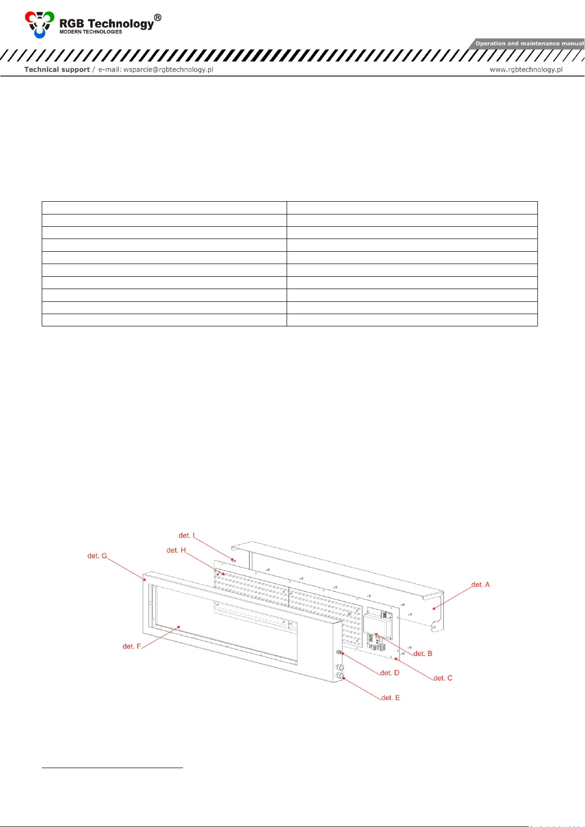
4. Device construction ............................................................................................................................................................3
4.1 WA-2 Professional construction ................................................................................................................................ 3
4.1.1 List of weighing scale display cables .................................................................................................................4
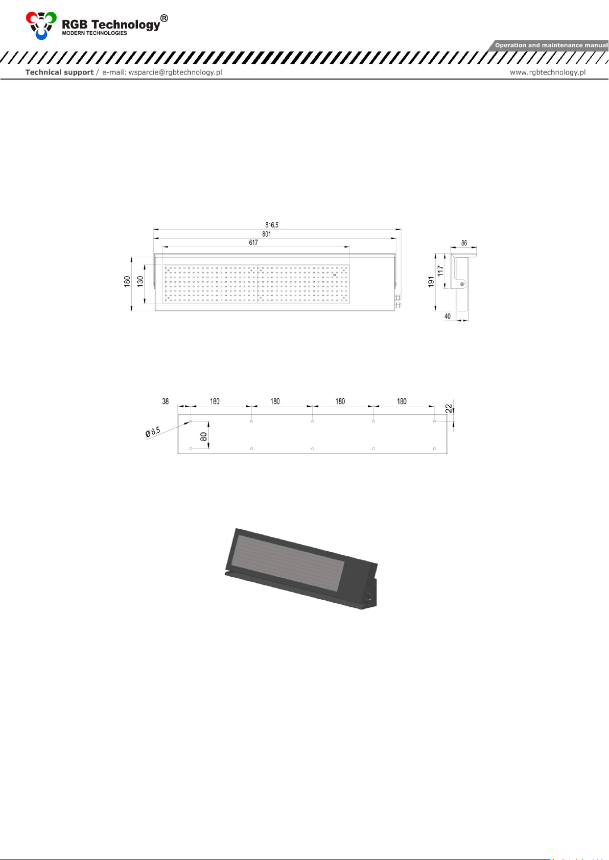
4.2 WA-2 Professional dimensions ..................................................................................................................................4
4.2.1 Dimensions without a roof................................................................................................................................4
4.3 Mounting the display for weighing scales ................................................................................................................. 4
4.3.1 Mounting bracket..............................................................................................................................................4
4.3.2 Roof as a stand of the device ............................................................................................................................4
5. Mounting the device ..........................................................................................................................................................4
5.1 WA-2 Professional device .......................................................................................................................................... 5
5.2 WA-2 Professional configuration ............................................................................................................................... 5
5.2.1 Defining communication protocols...................................................................................................................5
5.2.1.1 Embedded user menu (micro switch)...........................................................................................................5
5.2.1.2 Interface transmission parameters and communication speed ................................................................... 6
5.2.1.3 RGB WagSet 2 software................................................................................................................................6
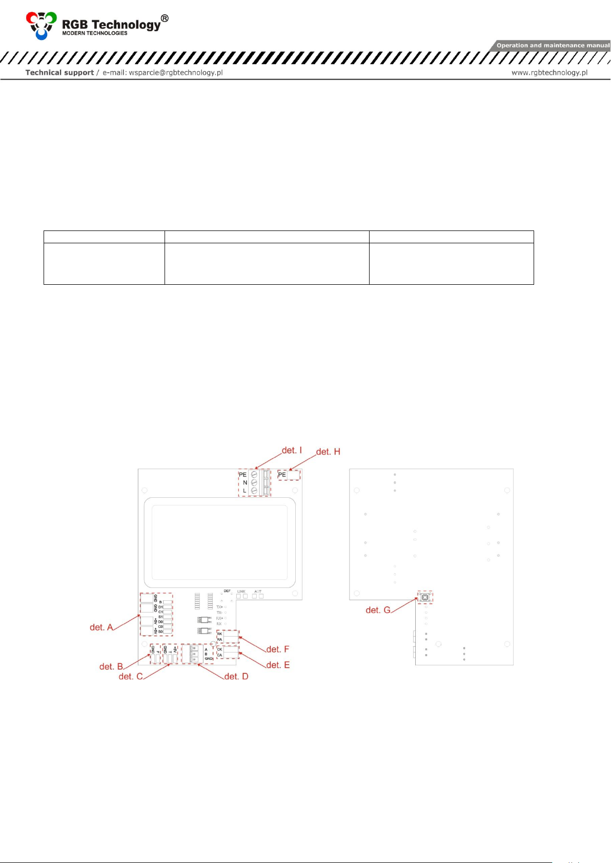
6. Weighing scale controller ................................................................................................................................................... 6
6.1 Weighing scale controller connectors .......................................................................................................................6
6.2 List of weighing scale controller connectors.............................................................................................................. 7
6.2.1 RS-232 connector: .............................................................................................................................................7
6.2.2 RS-485 / RS-422 connector: ..............................................................................................................................7
6.2.3 0/20mA digital current loop:............................................................................................................................. 7
7. Automatic brightness control of the display for weighing scales....................................................................................... 7
7.1 Lighting sensor ...........................................................................................................................................................7
8. Initial start-up ..................................................................................................................................................................... 8
9. Additional options .............................................................................................................................................................. 8
9.1 Temperature probe ................................................................................................................................................... 8
10. Disposal and recycling ........................................................................................................................................................ 8
10.1 Recycling of packing materials...................................................................................................................................8
10.2 Disposal of the device ................................................................................................................................................8
11. Most common errors during the installation .....................................................................................................................8

DTR_304-02-01-003_EN_a 3
1. Manufacturer
RGB Technology Sp. z o. o.
76-
POLAND
2. Specifications
The display for weighing scales WA-2 PROFESSIONAL
Dimensions: 1[mm]:
801 x 180 x 40
Digit height [mm]:
120
Permissible input voltage range (long-term):
Permissible input voltage range (short-term):
Acceptable input voltage frequency range:
Device operation temperature (ambient):
-
Device operation temperature (device surface):
-
Average power consumption:
8W
Casing tightness rating2IP:
65
Device weight:
6kg
3. Transport and storage
Care should be taken to properly protect the devices so as to eliminate any damage during transport. It is forbidden to
transport the devices in a collective package without adequate amortisation - each device must be packed
separately and cannot have freedom of movement during transportation.
Due to the protective packing the module should be stored in the temperature not lower than -
4. Device construction
WA-2 Professional is enclosed in a powder-coated metal housing. The properly assembled device meets the IP65
tightness requirements.
4.1 WA-2 Professional construction
The figure shows display for weighing scales WA-2 Professional3.
det. A roof; det. B controller; det. C back cover; det. D roof fixing screw; det. E cable gland; det. F viewfinder; det. G front of
the device; det. H LED modules; det. D back cover fixing screws;
Fig. 1
1Dimensions without roof.
2Specified on the basis of EN 60529.
3Explanatory figure.

4 DTR_304-02-01-003_EN_a
4.1.1 List of weighing scale display cables
1. Five-metre power cord core markings: blue, brown, yellow and green), terminated with WAGO
222-412 connectors on each core.
2. Five-metre signal cable interface; core markings: white -> RA, green -> RK).
4.2 WA-2 Professional dimensions
All dimensions shown in the drawings are given in [mm].
4.2.1 Dimensions without a roof
Fig. 2
4.3 Mounting the display for weighing scales
4.3.1 Mounting bracket
The roof functions as a mounting bracket (Fig. 4).
Fig. 3
4.3.2 Roof as a stand of the device
The appropriately mounted roof may function as a stand. The standard configuration of the mounting bracket
functions as a roof, but after its relocation, it may also serve as a stand with an adjustable angle (Fig. 4).
Fig. 4
5. Mounting the device
Correct mounting consists in installing the device on a flat surface or by using the roof as a stand (Fig. 4). Only
the proper mounting of the device ensures its proper operation and the maintenance of the device parameters,
like, among others, the housing tightness rating to satisfy the IP code.
NOTICE!
Before any installation or maintenance operations refer to the manual supplied by the manufacturer. Improper
connection to the mains power supply, incautious device installation, or improper use may cause the property
damage, loss of health or death from electrical shock! In addition, any failure to follow the manufacturer's
instructions may void your warranty.
NOTICE!
It is forbidden to make any additional mounting points or any holes in the device assembly components.

DTR_304-02-01-003_EN_a 5
5.1 WA-2 Professional device
The device is designed to display the measurement results transmitted by weighing terminals. For the proper
operation of the device, it is necessary to pre-configure it using the RGB WagSet 2 software available at
RGBtechnology.pl/soft or through the user menu embedded in the device.
5.2 WA-2 Professional configuration
The configuration of the device using RGB WagSet 2 enables:
1) Precise defining the communication protocol with any weighing terminal,
2) Defining the reaction to the events reported by the weighing terminal (eg. overloading, underloading,
instability, etc.),
3) Entering advertising text.
5.2.1 Defining communication protocols
5.2.1.1 Embedded user menu (micro switch)
The user menu embedded in the device allows you to select the communication protocol, display the information
about the software version, reset the device to the default settings. The micro switch, used to operate the menu, is
located inside the display housing, however, after unscrewing the lock screw (fig. 5, det. A) micro switch is
available through the thru-hole (fig. 5, det. B) without opening the device.
det. A lock screw; det. B thru-hole
rys. 5
The user menu is called up by pressing and holding the "DEF" micro switch and releasing it when the desired
option is displayed. Regardless of the option, you can exit the user menu by pressing the micro switch and
releasing it when switching between the options (when switching between the options, the display does not
display any information)
The user menu has the following options:
1) info This option enables displaying the software version. For the displays with the Ethernet interface,
additionally the network layer settings are given (the IP address, the network mask, the communication
port for the RGB WagSet 2 program, and the communication port for the weighing terminal). The info
option is exited automatically after displaying information.
2) proto This option allows you to select the display communication protocol for the cooperation with the
weighing terminals pre-loaded into the device memory . The amendments to the protocol are introduced
by pressing the micro switch. You can approve the protocol by holding the micro switch for a long time
(until the inscription "Saved" appears). The "proto" option is left after 30 seconds of the user inactivity.
3) custm The "custm" option allows you to choose a dedicated display communication protocol for the
cooperation with the weighing terminals of the selected customers. The protocols have special nonstandard
settings meeting the needs of a given customer. Setting the protocol is done in the same way as for the
"proto" option you can approve the selected protocol by holding the micro switch for a long time (until
the inscription "Saved" appears), while leaving the "custm" option is done automatically after 30 seconds of
the user inactivity.

6 DTR_304-02-01-003_EN_a
4) reset This option allows you to restore the default protocol of the display for weighing scales. In addition, in
the devices with the Ethernet interface, it allows you to restore the default settings of the network layer (IP
address: 192.168.0.11, network mask: 255.255.255.0, communication port for the WagSet2 software: 2102,
and the communication port for the weighing terminal). To restore the default settings, you should, during
the normal operation of the device, press the micro switch and hold it until you see the inscription "reset".
Hold the micro switch until the inscription "reset" starts blinking and do not release it until you see the
inscription "default". Releasing the switch before displaying the inscription "default" will stop restoring the
default settings and the display will continue to operate with the previously set parameters. Uploading new
network settings is possible only by using the RGB WagSet 2 software available at RGBtechnology.pl/soft.
5.2.1.2 Interface transmission parameters and communication speed
Interface
Transmission parameters
Communication speed
RS232, RS485, RS422, CL
Data bits: 7, Parity: Odd, Even
Data bits: 8, Parity: None, Odd, Even
Stop bits: 1
300, 600, 1200, 2400, 4800, 9600,
14400, 19200, 28800, 38400, 57600,
76800, 115200, 230400
Table 1
5.2.1.3 RGB WagSet 2 software
Using the WagSet 2 software, you can perform the advanced configuration of the device. The program allows you
to change, among others: the parameters of displaying the weighing result, entering and editing advertising text,
the display response to special situations such as: exceeded measurement range, etc. The detailed information
on the configuration from your computer can be found in the manual supplied with the RGB WagSet 2 program.
6. Weighing scale controller
The weighing scale controller is a device responsible for displaying the measurement result transmitted by the
weighing terminal.
6.1 Weighing scale controller connectors
det. A LED modules connector; det. B lighting sensor connector; det. C temperature probe connector; det. D RS-485/RS-422
connector; det. E 0/20mA digital current loop; det. F RS-232 connector; Det. G micro switch DEF;det. H soldering point of the
earthing; det. I mains power supply connector;
Fig. 6

DTR_304-02-01-003_EN_a 7
6.2 List of weighing scale controller connectors
Table 2 presents the description of the WEIGHING SCALES controller connectors (Fig. 8, det. B) in the WA-2
Professional display for weighing scales. The connectors are accessible after the disassembly of the back cover
(Fig. 8, det. C) by removing the front of the device (Fig. 8, det. A). Moreover, on the back cover, LED modules are
also fixed (Fig. 8, det. D).
det. A front of the device; det. B controller; det. C back cover; det. D LED modules
Fig. 7
NOTICE!
The disassembly of the housing must be made with the disconnected power supply.
Interface/ Function
Connector
symbols
Notes
STANDRAD4
RS-232
RA
RXD line of the RS-232 interface. The line should be
connected with the weighing terminal output.
RK
GND line of the RS-232 interface
0/20mA (CL) digital
current loop
CA
CL line of the current loop. The line should be connected
with the weighing terminal TDX output
CK
GND line of the current loop interface
RS-485 RS-422
A
RS-485 and RS-422 interface inverting line
B
RS-485 and RS-422 interface non-inverting line
GND
GND line of the RS-485 and RS-232 interface for use at
risk of a significant difference in the potentials of the
display mass and the weighing terminal mass
Table 2
6.2.1 RS-232 connector:
For configuration purposes, the user connects with the display for weighing scales via the RS-232 connector
(Fig. 6), using the computer with the RGB WagSet 2 software installed.
6.2.2 RS-485 / RS-422 connector:
For configuration purposes, the user connects with the display for weighing scales via the RS-485 or RS-422
connector (Fig. 6), using the computer with the RGB WagSet 2 software installed.
6.2.3 0/20mA digital current loop:
For communication purposes, the user connects with the display for weighing scales via the digital current loop
connector (Fig. 6), using the computer with the RGB WagSet 2 software installed.
7. Automatic brightness control of the display for weighing scales
7.1 Lighting sensor
In the standard version, the display for weighing scales has a lighting sensor included, which is placed on the LED
panel. The device, in response to the intensity of daylight, adjusts the brightness of the display for weighing
scales.
4On the PCB controller there are located all connectors available as standard, however, only the RS-232 interface cable (without a tip) is
led out.

8 DTR_304-02-01-003_EN_a
8. Initial start-up
Step 1: Make sure that all cables are properly connected,
Step 2: Make sure that all components have been installed in the correct orientation,
Step 3: Connect the device to the mains power source,
Step 4: If properly connected, the system will display moving arrows (<<<<), followed by the symbol of a hard
space (_) shown in the bottom right corner, which means that the user has 7 seconds to send the
configuration to the display for weighing scales. If the user does not enter the configuration, the display
for weighing scales will start running a demo, that is, a moving text (user text).
9. Additional options
9.1 Temperature probe
The temperature probe (Fig. 8) is available with two versions of a signal cable length 0.5m and 2m.
The probe enables measuring and displaying temperature only in . The detailed description of the
temperature probe is available in the DTR documentation according to the catalogue index number.
Fig. 8
10. Disposal and recycling
10.1 Recycling of packing materials
The packaging materials must be segregated , then recycled in accordance with local regulations for
waste disposal regulations.
10.2 Disposal of the device
The device can not be disposed with regular household waste!
According to Directive 2002 / 96 / EC ( WEEE ) , when repair is not economically reasonable, user is
obligated to hand over damaged or destroyed device to an appropriate disposal facility .
11. Most common errors during the installation
1Incorrect configuration uploaded to the display for weighing scales.
2Drilling additional mounting holes or holes in junction boxes.
Other manuals for WA-2 PROFESSIONAL
1
This manual suits for next models
1
Table of contents
Other RGB Technology Lighting Equipment manuals