CONCEPT II LED CEILING FAN
IMPORTANT SAFETY INSTRUCTIONS:
Before you begin installing the fan, shut power off at the circuit
breaker of the fuse box. Be cautious! Read all instructions and
safety information before installing your new fan. Review
accompanying assembly diagrams. Make sure that all electrical
connections comply with local codes, ordinances, or National
Electrical Codes. Hire a qualified electrician or consult a do-it-
yourself wiring handbook if you are unfamiliar with installing
electrical wiring. Make sure the installation site you choose allows
the fan blades to rotate without any obstructions. Allow a minimum
clearance of 7 feet from the floor and 18 inches from the tip of the
blades to the wall. If you are mounting the fan to a ceiling fan
outlet box, use a U.L. Listed metal octagonal outlet box marked
"Acceptable for Fan Support". Secure the box directly to the
building structure. The outlet box and its support must be able to
support the moving weight of the fan (at least 50 pounds) Do not
use a plastic box. Caution: To reduce the risk of injury use only the
screws provided with the outlet box in conjunction with the lock
washers provided with the fan. If you are mounting the fan to a
joist, make sure it is able to support the moving weight of the fan
(at least 50 pounds). After you install the fan, make sure that all
mounting components are secured to prevent fan from falling. Do
not insert anything into the fan blades while the fan is operating.
Turn the fan off and wait for the blades to stop completely before
proceeding with maintenance or cleaning.
WARNINGS:
TO REDUCE THE RISK OF FIRE, ELECTRIC SHOCK OR
OTHER PERSONAL INJURY, MOUNT FAN ONLY TO A
U.L. LISTED OUTLET BOX OR SUPPORTING SYSTEM
MARKED ACCEPTABLE FOR FAN SUPPORT AND USE
MOUNTING SCREWS PROVIDED WITH THE OUTLET
BOX IN CONJUCTION WITH THE LOCK WASHERS
PROVIDED WITH THE FAN. MOST OUTLET BOXES
COMMONLY USED FOR FAN SUPPORT OF LIGHTING
FIXTURES ARE NOT ACCEPTABLE FOR FAN SUPPORT
AND NEED TO BE REPLACED. CONSULT A QUALIFIED
ELECTRICIAN IF IN DOUBT.TO REDUCE THE RISK OF
PERSONAL INJURY, DO NOT BEND THE BLADE
HOLDERS WHILE INSTALLING, BALANCING THE
BLADES OR CLEANING THE FAN. DO NOT INSERT
FOREIGN OBJECTS BETWEEN ROTATING FAN
BLADES. TO REDUCE THE RISK OF FIRE OR
ELECTRONIC SHOCK, THIS FAN ONLY CAN USE
CFR-3T SOLID-STATE SPEED CONTROL WITH
TR111A-1 WALL CONTROL ONLY.
ASSEMBLY& INSTALLATION:
INSTALLING THE MOUNTING BRACKET
Tools Required: Phillips screw driver; slotted screw driver; step-
ladder; wire cutters; electrical tape.
WARNING: All of the parts, hardware and components have been
provided for your safety and the proper installation of your new
ceiling fan. The use of other parts, hardware or components not
supplied by Minka Aire® with the fan will void the Minka Aire®
Warranty. REMEMBER to turn off the power. Follow the steps below
to hang your fan properly:
Step 1. Attach the mounting bracket to the outlet box with two
screws provided with your outlet box. Make sure the bracket is firmly
secured. (Fig. 1)
Step 2. Lift fan into position by secure the safety cable onto the hook
from the ceiling mounting bracket. (Fig. 1)
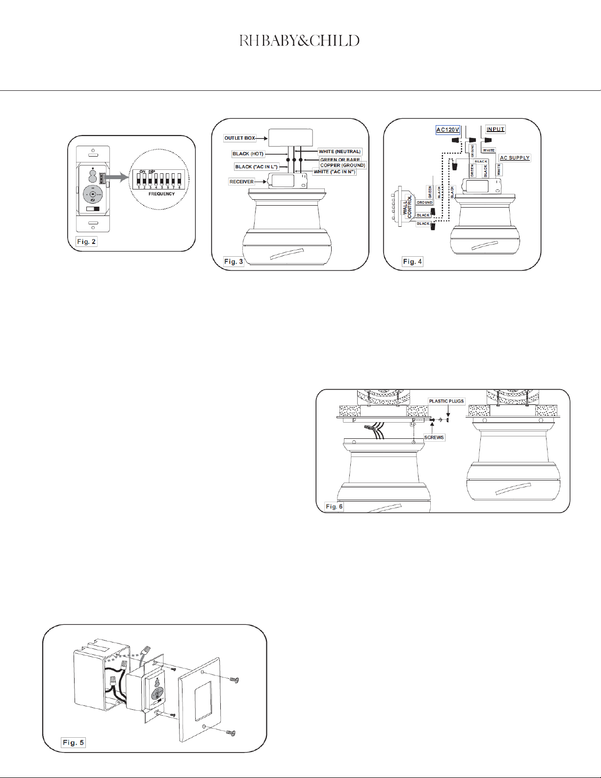
ELECTRICAL CONNECTIONS
WARNING: To avoid possible electrical shock be sure electricity is
turned off at the main fuse or breaker box before wiring. NOTE: The
Aire Control® System is equipped with a learning frequency function
which has 256 code combinations to prevent potential interference
from other remote units. The frequency on your Receiver and
Transmitter units have been preset at the factory. (Fig. 2) No
frequency change is necessary, should you desire to install another
fan within the same home or area with a separate frequency code
please see the "frequency interference" troubleshooting section of
this instruction manual to learn how to change the frequency.
Caution! The dip switches on the receiving unit are covered with a
rubber cover, remove the rubber cover and then have it replaced
after making any changes to the dip switches.
Step 1 Connect the fan supply (black) wire to the black household
supply wire as shown in Figure 3 & 4.
Step 2. Connect the neutral fan (white) wire to the white neutral
household wire.
Step 3 Connect the fan ground wire (green) to the household ground
wire.
Step 4. After all splices are made, check to make sure there are no
loose strands. As an additional precaution we suggest to secure the
plastic wire connectors to the wires with electrical tape.