ITALIAN TRAVERTINE FIRE TABLE ENGLISH
RH.COM
REVISION 04-11-22
iv. Place the appliance on a solid, flat, level surface where it will
not get excessively wet or submerged in water.
3. OPERATION
i. Do not use if damaged or malfunctioning.
ii. For decorative purposes only. Not suitable for continuous
operation. Do not use the appliance to heat or boil water or as
a cooking appliance. Do not put wood, charcoal, paper or other
combustible objects in the fire.
iii. MAD Design USA is not liable for any damage caused by using
the incorrect type of fuel.
iv. NEVER leave a fire unattended.
4. HOT SURFACE HAZARD
i. Due to high surface temperatures, keep children, pets, clothing
and furniture away from the unit during and for up to one hour
after use. As the unit is hot while in operation, contact with the
appliance may cause burns.
5. USING ACCESSORIES
i. Use only authorized accessories with your appliance.
ii. To reduce the risk of fire or injury, do not modify the appliance
in any way.
iii. The burner has not been tested with an unvented gas log set.
To reduce the risk of fire or injury, do not install an unvented
gas log set into this appliance.
For decorative media, you must:
- Ensure the decorative media does not interfere with the
burner parts.
- Confirm quality and suitability to ensure the media will not
explode or emit carbon monoxide or fumes when exposed to
extreme temperature variations.
- Fire accessories must not be smaller than 1⁄2" (12.7mm) in
diameter so as to not impede the burner parts.
iv. Do not use fittings or spare parts other than those available
from or recommended by the manufacturer of this appliance.
If you have any questions regarding any of the above
important safety information, please contact your retailer or
MAD Design USA.
Please store these warnings in a safe place for future reference.
Improper installation, adjustment, alteration, service, or
maintenance can cause injury or property damage. Read the
installation and maintenance instructions thoroughly before
installing or servicing this equipment.
It is imperative the burner be kept clean.
Do NOT use this appliance if any part of it has been underwater.
Immediately call a qualified service technician to inspect the
appliance and replace any part of the control system or gas
control that has been underwater.
Installation and service of this appliance should be performed by
qualified personnel. We recommend NFI-certified professionals
or technicians supervised by an NFI-certified professional.
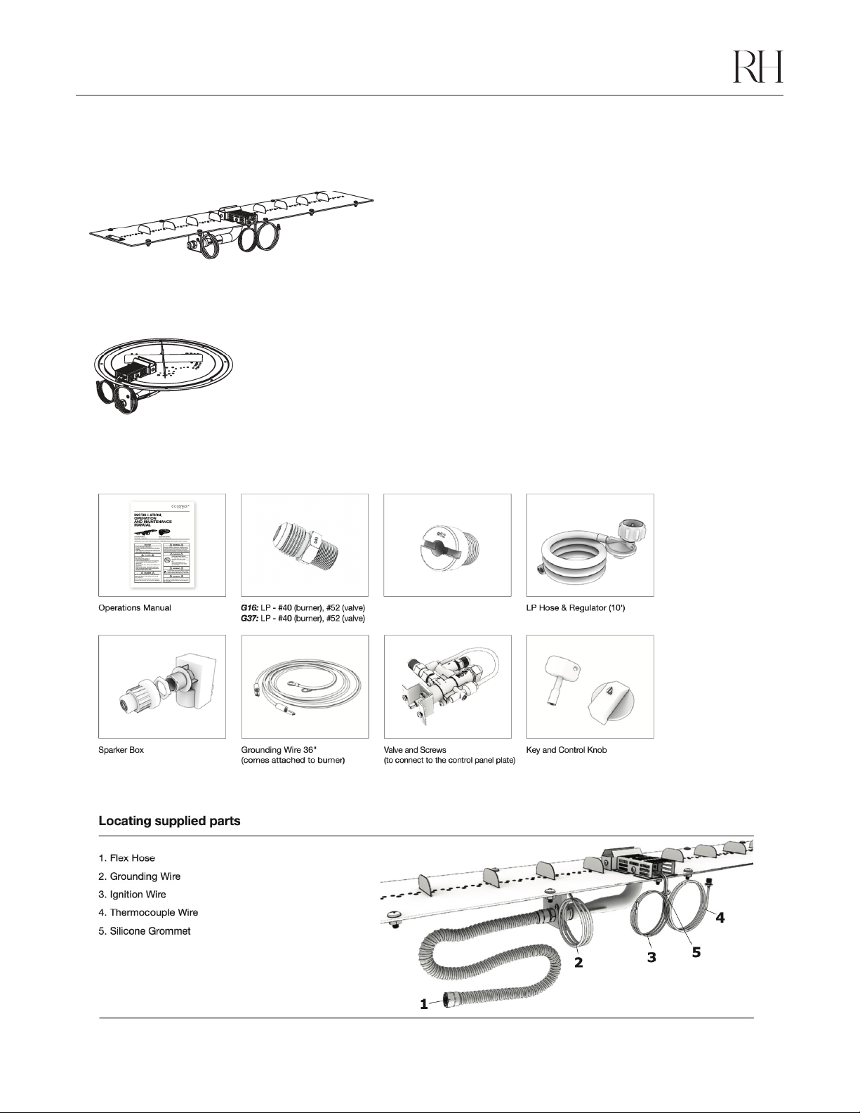
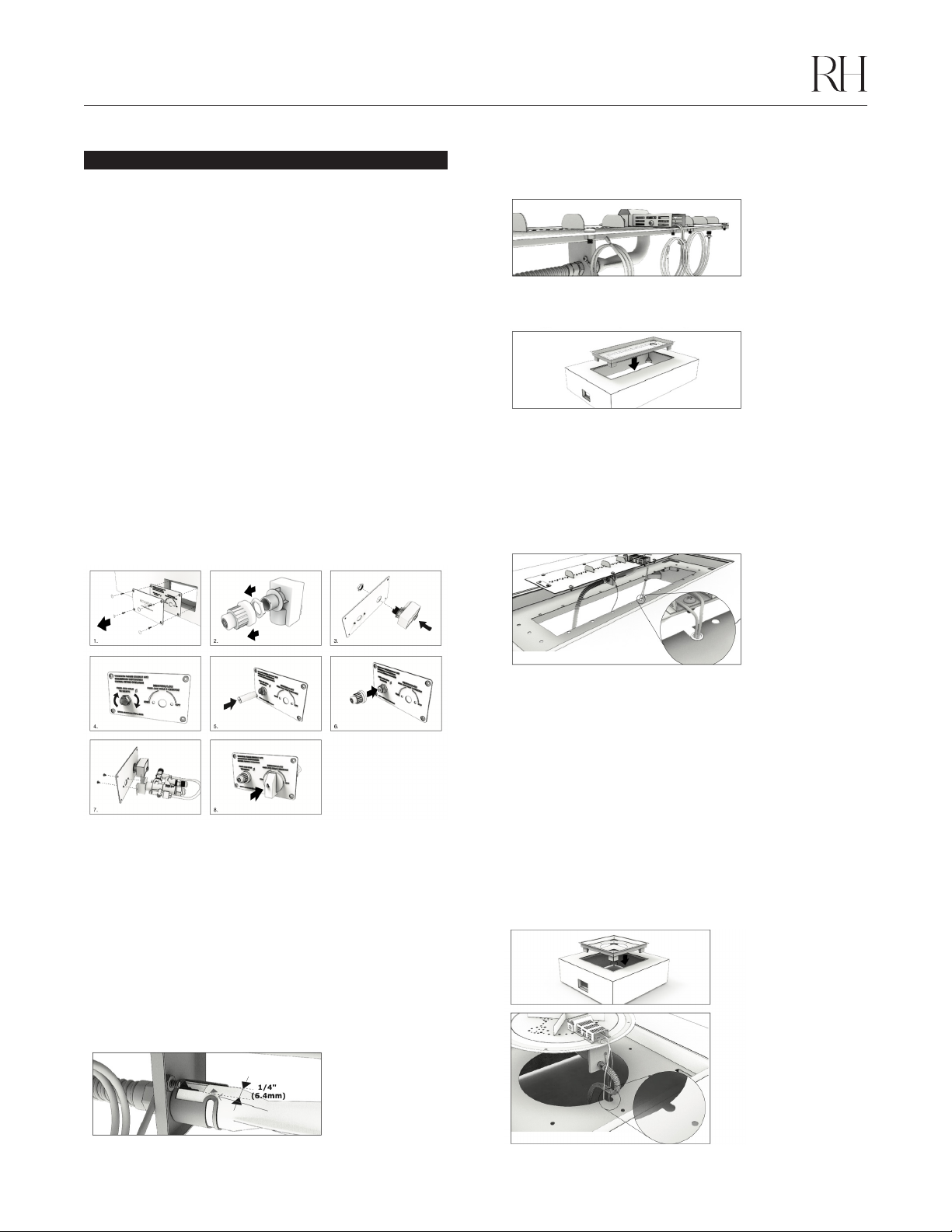
ASSEMBLY PREPARATION
When planning an appliance installation, it’s necessary to determine the
following information first:
Environmental Conditions
WARNING: Ensure that the fire from your appliance is positioned away from
flammable materials and other sources of ignition (combustible materials,
gasoline and other flammable vapors and liquids) at all times. Pay very close
attention to positioning the fire away from items that may move as a result of
wind and drafts (e.g. trees, curtains, paper, etc.).
The base of the burner within the model must never come into direct contact
with flammable materials.
Placing Your Appliance
Adequate and constant ventilation is important to keep the appliance
functioning properly and safely, including ventilation of the undersides.
Without air circulation underneath, heat can build up and cause improper
combustion. Do not remove the feet or operate the appliance with
missing feet.
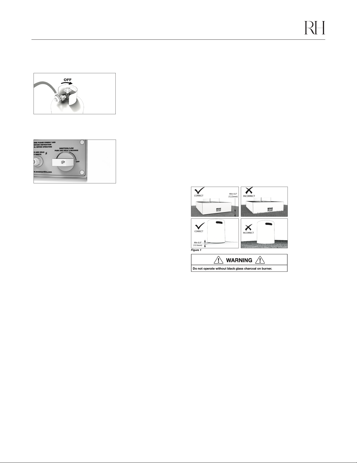
1. Place the appliance and the LP tank cover on a hard, flat surface that
is equal to or greater than the full length and width of the appliance. The
appliance and the LP tank cover can be placed on a combustible surface
(such as a wood deck) or on a non- combustible material (such as concrete).
Ensure that the specified clearances to the sides and above the appliance
are observed at all times (see figures 1 and 2).
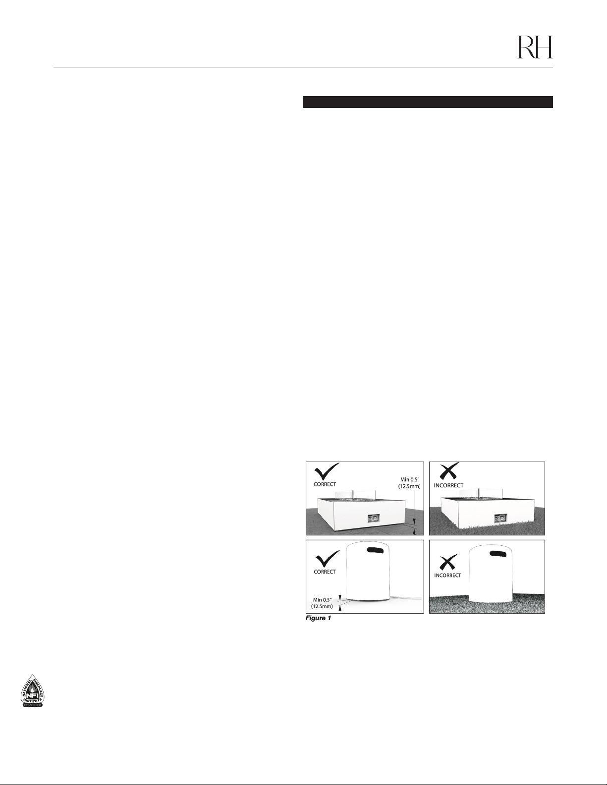
2. Maintain a minimum air space of 1⁄2" (12.5mm) between the ground
surface and the underside of the appliance sidewalls by adjusting the
articulating feet up or down as necessary.
3. Do not place the appliance over grass, artificial turf, carpet or any uneven
surface, as this will block the airflow underneath the appliance. See figure 1.
4. Follow the same instructions above for the LP tank cover. See figure 1.
Position the appliance adjacent to the gas supply line or LP gas
supply cylinder.
DO NOT place the appliance where it will get excessively wet or submerged
in water.
Minimum Clearances
Note: Measurements are for distances closest to the flame
Side clearances to fixed and stable furniture items that are not susceptible
to movement (such as lounges or patio furniture) must remain a minimum
of 24" (610mm) away from the flame at all times.