Rheem RXID-AW90A User manual

RXID-AW90A Whole House Dehumidifier
with fresh air ventilation
Installation Guide
Dehumidification
Fresh Air Ventilation
Compact Size
Energy Efficient
The whole house dehumidifier integrates high-
capacity dehumidification, fresh air ventilation,
and filtration, into a compact and easy to install
enclosure.
An automatic ventilation controller and dehumidi-
stat are included.
The dehumidifier removes 90 pints of water from
the air per day (80F, 60% RH) while only using 6.2
Amps of electricity.
The high moisture removal capacity helps main-
tain proper levels of humidity in most homes.
Dehumidification
The dehumidifier's high efficiency refrigeration
system is further enhanced with a heat exchanger to
achieve exceptional performance while keeping your
energy costs as low as possible.
Fresh Air Ventilation (optional)
Fresh air may be ducted to the unit and regulated
using an optional fresh air ventilation controller
along with a fresh air damper.
HVAC Installer: Please leave manual for homeowner.
69-2298-01

Dehumidifier • For HVAC Installer Only
69-2298—01 2
Table of Contents
Introduction ....................... 1
Features & Benefits ................. 1
Safety Precautions .................. 2
1. Intended Application ................ 3
2. Approvals ......................... 3
3. Specifications...................... 3
4. Installation ........................ 3
4.1 Installation Checklist ............. 3
4.1A Power Accessibility ......... 3
4.1B Accessibility ............... 3
4.1C Support Structure and
Suspension................ 4
4.1D Sizing Chart ............... 4
4.2 Electrical Requirements........... 4
4.3 Condensate Removal ............ 4
4.4 Ducting. . . . . . . . . . . . . . . . . . . . . . . . 4
4.4A Fresh Air / Supply Air ........ 4
4.4B Ducting for Fresh Air—Option . 5
4.4C Installation in a Basement or
Crawl Space with an Existing
Forced Air HVAC System ..... 5
4.4D Installation in an Attic with
an Existing Forced Air
HVAC System .............. 6
4.4E Installation in a Structure with
Two Forced Air HVAC Systems 7
4.5 Noise Abatement ................ 7
5. Maintenance ....................... 7
5.1 Air Filter ....................... 7
5.2 Optional Fresh Air Intake.......... 7
6. Wiring Diagrams .................... 7
7. Parts List ......................... 8
8. Service ........................... 8
8.1 Troubleshooting ................. 9
8.2 Refrigerant Charging ............ 10
8.3 Compressor/Capacitor
Replacement .................. 10
Safety Precautions
Read the installation, operation and maintenance instructions carefully before installing and
operating this device. Proper adherence to these instructions is essential to obtain maximum
benefit from your indoor air quality system.
READ AND SAVE THESE INSTRUCTIONS
• The device is designed to be installed INDOORS IN A SPACE THAT IS
PROTECTED FROM RAIN AND FLOODING.
• Install the unit with space to access the front panel for maintenance and
service.
• Avoid directing the discharge air at people, or over the water in pool areas.
• If used near a pool or spa; be certain there is NO chance the unit could fall
into the water, splashed and that it is plugged into a GFI GROUND FAULT
INTERRUPT OUTLET.
• DO NOT place the device directly on structural members.
• A drain pan MUST be placed under the unit if installed above a living area or
above an area where water leakage could cause damage.

For HVAC Installer Only • Installation Guide
3 69-2298—01
1. Intended Application for Dehumidifier
The dehumidifier is intended for use in residential
applications to reduce the indoor humidity levels
and increase comfort. With the optional ventilation
ducting and ventilation control hookup, the device
also provides precise amounts of ventilation air.
2. Approvals
The dehumidifier is certified by ETL to meet UL 474
and CSA 22.2 No. 92.
3. Specifications
Model: RXID-AW9A
Electrical: 110-120 VAC, 6.3 Amps,
60 Hz, grounded
Capacity: 97 Pints/Day(80ºF[27ºC],
60% RH)
114 Pints/Day (90ºF
[32ºC], 60% RH)
130 Pints/Day (100ºF
[38ºC], 60% RH)
Blower: 240 CFM @ 0.0 in. WG
220 CFM @ 0.4 in. WG
Coverage (sq ft): Up to 2800
Inlet air temperature range: 55°F min., 100°F max.
Operating Exterior Temp: 56-130ºF(13-54ºC)ducted
56-100ºF (13-38ºC)
unducted
Air Flow: 200 CFM without external
ducting
Discharge Air Temp: 105ºF (41ºC) (80ºF [27ºC],
60% RH intake)
Refrigerant Charge: 1 lb., 12 oz. R22
Duct Connections: 6 in. Round Inlet
10 in. Round Inlet
10 in. Round Outlet
Filter Size: Pleated MERV 11:
14" x 14" x 1"
Filter Efficiency: Standard MERV-11 (65%
ASHRAE Dust Spot)
Unit Size: 34.5"L(w/oDuctCollars);
40.5"L (w/ Duct Collars)
x 15.75"W x 20.875"H
(See Fig. 1)
Unit Weight: 92 lbs
Shipping Size: 42"L x 25.875"H x 20.5"W
Weight: 99 lbs
Power Cord: 7.5 ft, 115V With Ground
Drain Connection: 3/4 in. Threaded MPT
M28622
6
(152)
10
(254)
INLET VIEW
10
(254)
OUTLET VIEW
SIDE VIEW
15-3/4 (400)
20-7/8
(530)
34-1/2 (876) 43-1/2 (1092)
Figure 1: Dimensions.
4. Installation
4.1 Installation Checklist
IMPORTANT: Prior to installation of the
dehumidifier, the following checklist should
be reviewed.
The dehumidifier can be installed in a variety of
locations to meet the owner’s needs, and integrate
with existing forced air systems or existing ductwork
if desired. Choose a location with consideration
to accessibility for service, drain availability, and
power outlet location.
4.1A Power Accessibility
Unit should be located in an area where the cord’s
length (10') should easily reach a 115 VAC electrical
outlet with a minimum of a 15 A circuit capacity.
4.1B Accessibility
The installed dehumidifier should have at least 14
inches of clearance in the front of the device to
service the filter.

Dehumidifier • For HVAC Installer Only
69-2298—01 4
Place the dehumidifier on supports to raise the
base of the unit. Do not place the dehumidifier
directly on structural building members without
vibration absorbers or unwanted noise may result.
The dehumidifier may be suspended from structural
members by supporting the entire base of the unit
via cross members, rigid frame, or the like. Do
not hang the dehumidifier from the cabinet.
Remember to place a drain pan under the unit if
it is suspended above a finished area or above an
area where water leakage could cause damage.
4.1D Sizing Chart
*This sizing chart is based on extreme climates where
Rh levels are between 70 and 90% outdoor Rh. For
less extreme climates then larger homes can be
adequately served. Actual requirements may vary.
4.2 Electrical Requirements
Dehumidifier Capacity Required to
Maintain Desired Indoor Rh*
Home Size
(square
feet)
60% Indoor
Rh
55% Indoor
Rh
50% Indoor
Rh
Pints/day Pints/day Pints/day
2080 49-54 55-58 71-78
2600 61-68 65-72 90-97
3120 75-82 79-86 95-110
WARNING: Installation must be performed
by a qualified service technician and must
comply with local codes. Remove power to
the device before installing or servicing the
device. Failure to connect the device
according to these instructions may result in
damage to the device or the controls.
The dehumidifier plugs into a common grounded
115VAC outlet. The device draws 6.3 Amps under
normal operating conditions. If used in an area
which may become wet, a ground fault interrupter
(GFI) protected circuit is recommended.
IMPORTANT: Do not install the humidistat
where it may not accurately sense the relative
humidity such as near HVAC supply registers,
near exterior doors, on an outside wall, near
a window, or near a water source.
Refer to Section 6 for typical hookup diagrams.
Some of the control wires leaving the dehumidifier
may not be used with certain installations and
should be left unconnected with wire nuts taped
onto the stripped ends for safety.
4.3 Condensate (Water) Removal
The dehumidifier removes a large amount of moisture
from the air and the device must be connected to a
drain line that will carry away the excess water. A
trap in the drain line is recommended and may be
required by some local codes.
The drain line should be connected to the 3/4"
male pipe thread adaptor on the front of the
dehumidifier.
Care should be taken to install the drain line with
a continuous slope of 1" per 10' to assure proper
water removal.
4.4 Ducting
IMPORTANT: When connecting ventilation
duct, remove the label and 6" round
insulation plug from the ventilation duct
opening. If not using ventilation feature,
leave the insulation intact.
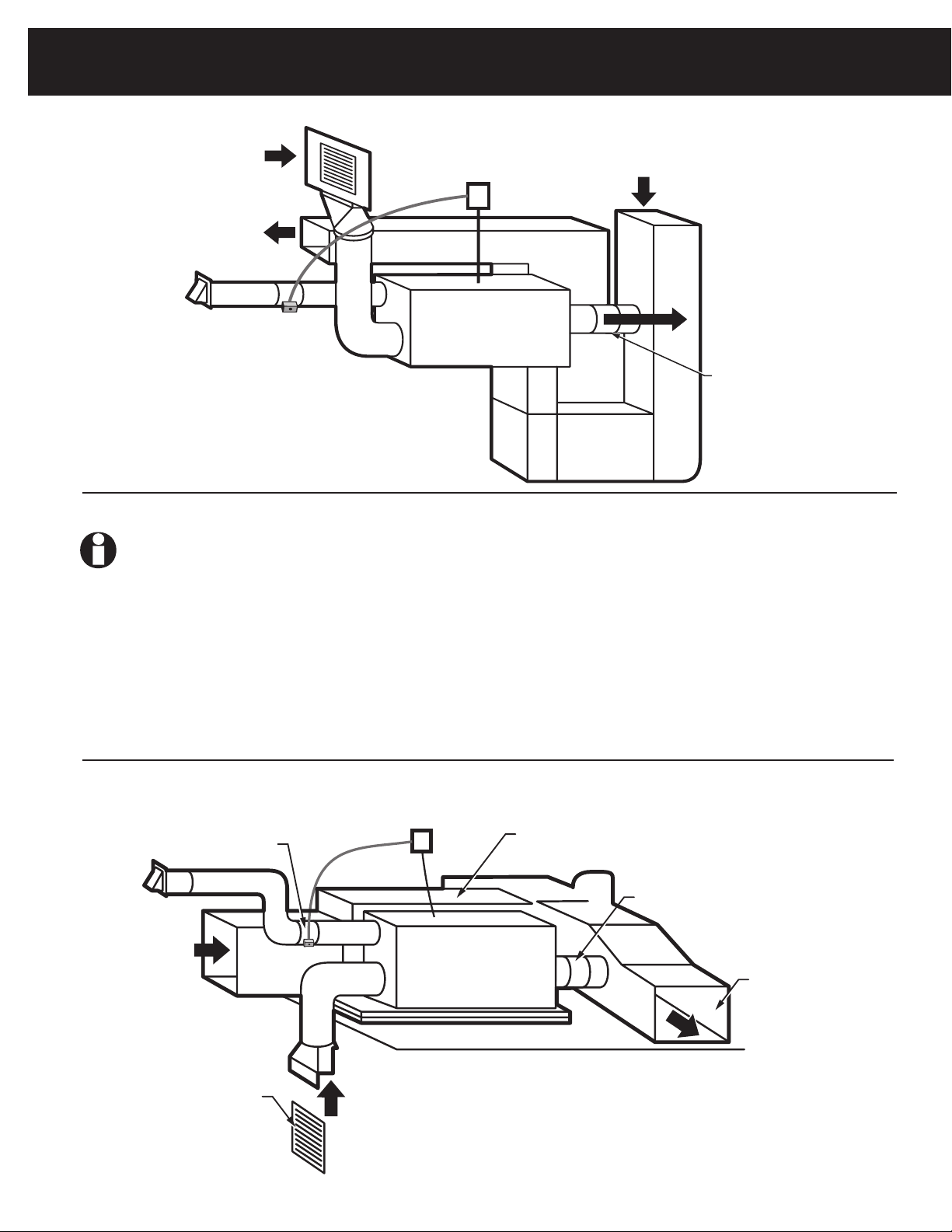
For the ideal installation, draw air from the central
part of the home and return it to the isolated areas
of the home like the bedrooms, den, utility room, or
family room. See Figure 2. Alternative installation
option can be completed by drawing air directly
from the return ducting and distributing through
the supply air to the home.
Another installation option is ducting directly from
the return and distributing directly back into the
system's return. See Figure 3. Fresh air ventilation
is optional and does not have to be ducted in order
for the dehumidifier to properly function.
IMPORTANT: DO NOT draw air directly from
the kitchen, laundry, or isolated basement.
Air may be drawn from a basement that is open
to the home. All flexible ducting connected to the
dehumidifier should be UL listed.
A short piece of flexible ducting on all dehumidifier
duct connections is recommended to reduce noise
and vibration transmitted to rigid ductwork in the
structure. Ducting the dehumidifier as mentioned
requires consideration of the following points:

For HVAC Installer Only • Installation Guide
5 69-2298—01
• Duct Sizing: For total duct lengths up to
25', use a minimum 10" diameter round or
equivalent rectangular. For longer lengths,
use a minimum 12" diameter or equivalent.
Grills or diffusers on the duct ends must
not excessively restrict airflow.
• Isolated Areas: Effective dehumidification
may require that ducting be branched to
isolated, stagnant air flow areas.
Use 8" or larger diameter branch ducting to each
of two or three areas, use 6" or larger to each of
four or more areas. Provisions must be made to
provide airflow from supply locations to central
return location. Proper air distribution is important
to ensure even humidity control throughout the
structure.
Fresh air may be brought into the structure
by connecting an insulated duct from outside
the structure to the 6" inlet of the dehumidifier.
Advantages of this form of ventilation include:
1. Outside air is filtered before entering the
building.
2. Outside air will be dehumidified before
entering if the dehumidifier is running in
dehumidification mode.
3. Drawing air from outside and blowing inside
aidsinslightlypressurizingthestructure.This
helpspreventdirtyandhumidairfromentering
elsewhere.
Exhaust fans are recommended in the
bathrooms and kitchen.
An insulated 6" diameter duct is generally sufficient
to provide up to 75 CFM of outside air. Large
quantities of outside air will impact dehumidifier
performance positively or negatively, depending
upon the inside and outside air conditions.
Figure 2: Ducting to isolated areas. Figure 3: Ducting from main return trunk to supply trunk.
FRESH AIR
INTAKE
(OPTIONAL)
SUPPLY AIR
DUCTING TO
ISOLAT ED AREAS
INDOOR AIR
RETURN
M29064
FRESH AIR
CONTROLLER
(OPTIONAL)
FRESH AIR
MOTORIZED
DAMPER
(OPTIONAL)
FRESH AIR INTAKE (OPTIONAL)
FRESH AIR
CONTROLLER
(OPTIONAL)
INDOOR AIR
SUPPLY
ATTIC INSTALLATION
INDOOR AIR
RETURN
SUPPLY AIR
HEATING AND
A/C UNIT
FRESH AIR
MOTORIZED
DAMPER
(OPTIONAL)
DEHUMIDIFIER
M29065
The outside air duct should be connected to the 6"
round collar on the side of the unit. The amount of
outside air can be restricted by the blade damper
in the 6" collar. The actual amount of ventilation
air being delivered through the ventilation ducts
must be measured in each installation. Refer to the
instructions provided with the Ventilation Control
for proper setup instructions.
4.4C Installation in a Basement or Crawl Space
with an Existing Forced Air HVAC System
Install a separate 10" return for the dehumidifier in
a central area of the structure. Optional: Duct the
supply of the dehumidifier to a 10" x 10" x 10" tee/
damper, adjusted to 20% open to the basement.
Duct the other side of the tee to the air supply of
the existing HVAC system with a backdraft damper.
Connect a duct from outside to the 6" collar of the
dehumidifier if you wish to provide ventilation air. See
Figure 4.
Instead of installing a separate return to the
dehumidifier, and if the existing system has multiple
returns, it is possible to select one to disconnect
from the existing forced air system and use it for the
dedicated dehumidifier return. Always select a return
from a central location in the structure in an area that
is always open to the rest of the structure. Do not use
a return from a room that may have its door closed
much of the time.

Dehumidifier • For HVAC Installer Only
69-2298—01 6
IMPORTANT: ALWAYS install a catch pan
with a drain or float interrupt for condensate
under the dehumidifier in an attic or conden-
sate may damage the living space below.
The interrupt switch should be installed in series
with the field wire that connects the blue lead from
the dehumidifier to the dehumidistat. If overflow
occurs, this switch opens the compressor
control circuit and stops water production before
the catch pan overflows. The dehumidifier will
continue to ventilate or circulate air as normal,
but will not dehumidify until this switch closes.
One method of installation is to create a separate
return for the dehumidifier in a central area of
the structure. Duct the supply of the dehumidifier
to the air supply of the existing HVAC system.
Connect an insulated duct from outside to the 6"
collar of the dehumidifier if you wish to provide
fresh air. Adjust a damper in the duct to provide the
desired amount of fresh air. See Figure 5.
Figure 4: Basement or crawl space installation.
FRESH AIR
INTAKE
(OPTIONAL)
FRESH AIR
CONTROLLER
(OPTIONAL)
INDOOR AIR
SUPPLY
M29067
INDOOR AIR
RETURN
INDOOR AIR
RETURN
SUPPLY AIR
HEATING AND
A/C UNIT
FRESH AIR
MOTORIZED
DAMPER
(OPTIONAL)
DRY AIR TO
BASEMENT
M29066
FRESH AIR
INLET HOOD
(OPTIONAL)
FRESH AIR
MOTORIZED
DAMPER
(OPTIONAL)
HEATING A/C
SUPPLY AIR
FRESH AIR
CONTROLLER
(OPTIONAL)
HEATING A/C
RETURN AIR
INDOOR
AIR RETURN
6 IN.
BACKDRAFT
DAMPER
Figure 5: Attic Installation.

For HVAC Installer Only • Installation Guide
7 69-2298—01
4.4E Installation in a Structure with No Existing
Forced Air HVAC System
When installing the dehumidifier in a structure that
does not have a forced air HVAC system, a single
return for the dehumidifier should be installed in
central open area of the structure.
DO NOT locate the return in a bathroom or a kitchen.
The supplies of the dehumidifier should be located in
the remote areas of the structure (such as bedrooms,
den, etc.). By ducting this way, the air inside the
structure will circulate through the dehumidifier to be
filtered and dehumidified.
6" diameter duct is recommended for branches to
the bedrooms, 8" diameter duct is recommended for
branches to larger areas. Connect an insulated duct
from outside to the 6" collar of the dehumidifier if
you wish to provide ventilation. See Figure 6.
4.5 Noise Abatement
A length of 10' or more of acoustical flex ducting on
the outlet of the dehumidifier will reduce air noise from
the fan. A length of flexible ducting on all dehumidifier
duct connections is recommended to reduce noise
transmitted to rigid ductwork in the structure.
5. Maintenance
5.1 Air Filter
The dehumidifier is equipped with a MERV 11
media filter. This filter should be checked every
three months and replaced every six months.
Operating the unit with a dirty filter will reduce
dehumidifier capacity and efficiency and may
cause the compressor to cycle off and on unnec-
essarily on the defrost control.
CAUTION: Operate the unit only with a
genuine Honeywell filter installed to assure
proper performance of the unit.
Figure 6: Install with no forced air HVAC system.
6. Wiring Diagrams
Figure 7: Dehumidistat only—No fresh air ventilation.
Figure 8: Dehumidistat including fresh air ventilation.
M29068
FRESH AIR
INLET HOOD
(OPTIONAL)
INDOOR
AIR RETURN
FRESH AIR
MOTORIZED
DAMPER
(OPTIONAL)
FRESH AIR
CONTROLLER
(OPTIONAL)
SUPPLY
AIR
DEHUMIDISTAT
RXID-AW90A
24VAC FOR POWERED
HUMIDISTAT
WHITE - COMMON
RED - 24V COMMON
YELLOW - 24V POWER
BLUE - DEHUMIDIFIER AND FAN OPERATION
GREEN - FAN OPERATION ONLY
M29069
DEHUMIDISTAT
RXID-AW90A
24VAC FOR
POWERED
HUMIDISTAT
M29070
FRESH AIR
CONTROLLER
VENTILATION
OVERRIDE
SWITCH
VENTILATION
DAMPER
DAMPER
REMOTE
1CONNECT VENTILATION CONTROL TO THE HVAC SYSTEM AS
PER CONTROL LITERATURE.
1
WHITE - COMMON
RED - 24V COMMON
YELLOW - 24V
POWER
BLUE - DEHUMIDIFIER
AND FAN OPERATION
GREEN - FAN
OPERATION ONLY
5.2 Optional Fresh Air Intake
Check and clean the screen on the outdoor fresh
air intake port seasonally. The screen may become
plugged during the seasons when there are many
particles in the outdoor air.

Dehumidifier • For HVAC Installer Only
69-2298—01 8
7. Parts List
For replacement parts contact your installing contractor.
Part Number Description
RXID-AW90A 90-Pint Dehumidifier with Manual Dehumidistat Control
50018994-001 14" x 14" x 1" MERV 11 Filter
50018995-001 10" Back Draft Damper
50018994-001 MERV 11 Filter
50018995-001 10-in. Backdraft Damper
50027976-001 Blower Assembly
50027977-001 24VAC Transformer
50027978-001 SPDT 15A Relay
50027979-001 SPST 30A Relay
50027980-001 Compressor
50027981-001 Leveling Feet (4)
8. Service
CAUTION:Servicing the dehumidifier with its high pressure refrigerant system and high voltage circuitry
presents a health hazard which could result in death, serious bodily injury, and/or property damage.
Service should only be performed by a qualified service technician.

For HVAC Installer Only • Installation Guide
9 69-2298—01
8.1 Troubleshooting
No dehumidification, neither fan nor compressor
run with fan switch and ventilation timer OFF.
1. Unit unplugged or no power to outlet.
2. Humidity control set too high or defective.
3. Loose connection in internal or control wiring.
4. Defective Compressor relay.
5. Defective control transformer.
6. Low pressure control open.
7. Optional Condensate Pump Safety Switch
open.
No dehumidification, compressor does not run
but fan runs when there is a call for dehumidi-
fication and the ventilation control is OFF.
1. Defective compressor run capacitor.
2. Bad connection in compressor circuit.
3. Defective compressor overload.
4. Defective compressor.
5. Defrost thermostat open.
6. Optional Condensate Pump Safety Switch
open.
Fan runs when there is a call for dehumidifica-
tion and the ventilation control is OFF, but the
compressor cycles on and off too frequently.
1. Low ambient temperature and/or humidity
causing unit to cycle through defrost mode.
2. Defective compressor overload.
3. Defective compressor.
4. Defrost thermostat defective.
5. Dirty air filter(s) or airflow restricted.
6. Low refrigerant charge, causing defrost
control to cycle.
7. Bad connection in compressor circuit.
Fan does not run with fan switch in either
position.
Fan does not run with ventilation
activated. Compressor runs briefly but
cycles on & off with humidity control
turned to ON.
1. Loose connection in fan circuit.
2. Obstruction prevents fan rotation.
3. Defective fan.
4. Defective fan relay.
5. Defective fan capacitor.
Evaporator coil frosted continuously, low
de-humidifying capacity.
1. Defrost thermostat loose or defective.
2. Low refrigerant charge.
3. Dirty air filter(s) or airflow restricted.
Unit not providing ventilation.
1. Check control wire connections (check
connections at fresh air damper also).
2. Defective fresh air damper.
3. Dirty air intake. Clean outside intake hood.
Unit removes some water, but not as much as
expected.
1. Air temperature and/or humidity have
dropped.
2. Humidity meter and or thermometer used
are out of calibration.
3. Unit has entered defrost cycle.
4. Air filter dirty.
5. Defective defrost thermostat.
6. Low refrigerant charge.
7. Air leak such as loose cover or ducting
leaks.
8. Defective compressor.
9. Restrictive ducting.
10. Optional Condensate Pump Safety Switch
open.

Dehumidifier • For HVAC Installer Only
69-2298—01 10
Unit Test to determine problem:
1. Detach field control wiring connections
from main unit.
2. Connect the yellow and green pigtails from
the main unit together; only the impeller
fan should run. Disconnect the wires.
3. Connect the yellow and blue pigtails from
the main unit together; the compressor and
impeller fan should run.
4. If these tests work, the main unit is
working properly. You should check the
control panel and field control wiring for
problems next.
5. Remove the control panel from the
mounting box and detach it from the field
installed control wiring. Connect the blue,
yellow, and green wires from the control
panel directly to the corresponding colored
pigtails on the main unit. Leave the violet,
white, and red wires disconnected!
6. Turn on the fan switch; the impeller fan
should run. Turn off the fan switch.
7. Turn on the humidity control; the
compressor and impeller fan should run.
8. If these tests work, the problem is most
likely in the field control wiring.
8.2 Refrigerant Charging
If the refrigerant charge is lost due to service or a
leak, a new charge must be accurately weighed in.
If any of the old charge is left in the system, it must
be recovered before weighing in the new charge.
Refer to the unit nameplate for the correct charge
weight and refrigerant type.
8.3 Compressor/Capacitor Replacement
This compressor is equipped with a two terminal
external overload and a run capacitor, but no start
capacitor or relay.
CAUTION-ELECTRICAL SHOCK HAZARD:
Electrical power must be present to perform
some tests. These tests should be performed
by a qualified service person.

For HVAC Installer Only • Installation Guide
11 69-2298—01
5 years from date of purchase (contact the Rheem Parts Distribution Center for more information).
Warranty Information
Dehumidifier • For HVAC Installer Only

Dehumidifier • For HVAC Installer Only
“In keeping with its policy of continuous progress and product improvements, Rheem reserves the right to make changes without notice.”
®U.S. Registered Trademark
©2009
69-2298—01 M.S. 1-09
RHEEM
AIR CONDITIONING
DIVISION
5600 Old Greenwood Road, Fort Smith, Arkansas 72908
Before proceeding with installation,
refer to installation instructions
packaged with each model, as well
as complying with all Federal, State,
Provincial, and Local codes.
PrintedinU.S.A.onrecycledpaper
containing at least 10% post-
consumer paper fibers.
Table of contents
Popular Dehumidifier manuals by other brands

Yoer
Yoer DRYO DE02W manual

Roper
Roper RD50CBM2 Use & care guide

Toshiba
Toshiba TDDP7011ES2 user manual

Prem-I-Air
Prem-I-Air EH1384 manual

Seaira Global
Seaira Global WatchDog NXT60 Installation and operation manual

Mondial Designs Limited
Mondial Designs Limited AIR COMFORT DM-01 Instruction and Technical Service Manual