manuals.online logo
Brands
  1. Home
  2. •
  3. Brands
  4. •
  5. Rheem
  6. •
  7. Water Heater
  8. •
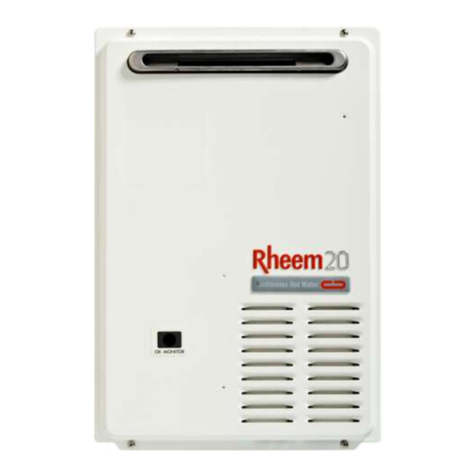
  9. Rheem 86VP6S Installation guide

Rheem 86VP6S Installation guide

WARNING
•Please read this Installation and Warranty Manual carefully before installation and use of the appliance. In particular, please pay
special attention to the Safety Instruction and Warnings. These instructions must be read in conjunction with other instructions
affixed to the appliance.
•This appliance must only to be installed by persons authorised for the installation of electric water heaters in accordance with all
Local and Government Regulations.
•For Safe Performance, this Storage Water Heater is supplied with a Thermostat, Thermal Energy Cutout, and Temperature &
Pressure Relief Valve. These devices must be installed and not tampered with or removed. The water heater must not be
operated unless each of these devices is fitted and is in working order.
•Please leave this manual with the homeowner upon completion of installation.
TECHNICAL DATA AND PRODUCT DIMENSIONS
LEFT HAND CONNECTION SHOWN
Model Number
86VP6S
86VP10S
86VP15S
86VP20S
86VP30S
Actual Capacity
Litres
25
42
50
75
100
Nominal Capacity
US Gallons
6
10
15
20
30
Rated Power
kW
2.7-3.3 kW, 220-240 V a.c. 50-60Hz
Approx. Heat Up Time to 60°C
min.
20
34
41
61
81
Height
A
mm
460
487
554
764
973
Diameter
B
mm
377
461
Spacer Bracket
C
mm
100
Wall Mounting Bracket
D
mm
286
292
359
568
777
Temperature Setting
ºC
Factory Set 65 (Max 70)
Rated Pressure
kPa
1000
Max. Inlet Water Pressure
kPa
800
Thread Sizes for Water Inlet & Outlet
Rp 20 (3/4" x 14)
Thread Size for Safety Valve
Rp 20 (3/4" x 14)
Shipping Weight
kg
16
21
23
29
36
Heat up time is calculated based on incoming temperature of 25°C
Diagram 1
FEATURES
•Mains pressure storage water heater ensures stable hot
water supply.
•Various tank capacities available –allowing simultaneous
multi point hot water usage.
•The adjustable thermostat automatically controls the
electricity supply to the heating unit so constant
temperature is maintained.
•Safety devices such as over temperature cut out and
Temperature and Pressure Relief (TPR) valve are
standard features.
•The temperature is preset at 65°C for safety and is
economical to operate. The temperature thermostat
comes complete with built in reset switch.
•The life span of the tank is greatly extended by Rheem’s
exclusive “Rheemglas” vitreous enamel lining and
sacrificial anode rod, ensuring years of trouble free
performance.
•Thick Polyurethane foam is environmentally friendly, free
of CFC enabling the water heater to be more energy
efficient by retaining heat and reduce operating costs.
•Heater jacket is protected by industrial strength
prepainted steel –a thick gauge precoated zinc steel
having exceptional strength and corrosion resistance.
ELECTRIC STORAGE WATER HEATERS
INSTALLATION, OPERATING INSTRUCTIONS AND WARRANTY CONDITIONS
1
•SAFETY
•This appliance is not intended for use by persons (including
children) with reduced physical, sensory or mental
capabilities, or lack of experience and knowledge, unless
they have been given supervision or instruction concerning
the safe use of the appliance by a person responsible for
their safety. Children should be supervised to ensure that
they do not play with the appliance.
•CAUTION: In order to avoid a hazard due to inadvertent
resetting of the thermal cutout, this appliance must not be
supplied through an external switching device, such as a
timer, or connected to a circuit that is regularly switched on
and off by an appliance or utility.
•The water heater must have provision for drainage in the
event that the water heater leaks or connection pipes break.
•The water heater is rated 220-240V/50Hz AC, single phase.
•The installation of the Electrical power supply cable must be
correctly sized to safely carry the maximum current draw of
the appliance. Ensure all earth wires and connections are
separated from the neutral circuit.
•Ensure that the electrical connections are undertaken by a
qualified electrician complying with Local Code of Practice.
•Power must not be turned on until the water heater is filled
with water. Open all hot water taps/faucets to release
trapped air until only water is discharged.
•Temperature over 50°C may cause scalding. Please mix
cold water with hot water to obtain the right bathing
temperature.
•Please operate the Temperature and Pressure Relief Valve
(TPR) manually at least once every 6 months to remove lime
deposits and verify that the drain pipe from the valve is not
blocked.
•Power must be turned off before any service and
maintenance work can commence. All work must be
performed by a qualified technician.
•For replacement of parts, please use original parts from
manufacturer. Use of non-approved parts will result in a void
the manufacturer’s warranty.
•Water may drip from the discharge pipe of the TPR valve
during normal expansion. The discharge pipe should be left
open to the atmosphere preferably 150 mm above the
nearest floor trap. On no accounts must the drain pipe be
plugged. Blockage of the TPR discharge pipe may cause
serious damage and will void the manufacturer’s warranty.
Warning –Scalds Minimisation. To minimise scalding,
especially for those people in high risk categories ie. Young
children, people with incapacitating medical conditions,
elderly people, etc, this unit must be installed in accordance
with all local and government regulations, and the use of
secondary devices such as a suitable tempering valve or
anti-scald water shut-off valve. (If a tempering valve is used,
refer to its servicing instructions for periodic maintenance.)
•Hot water must be stored at a minimum of 60°C to inhibit the
growth of Legionella bacteria.
•All sanitary outlets used primarily for personal hygiene shall
deliver hot water not exceeding: a). 45°C for early childhood
centres, primary and secondary schools and nursing homes
or similar facilities for young, aged, sick or disabled persons;
and b). 50°C in all other buildings.
INSTALLATION AND CONNECTION (by authorised person)
CHOOSING WHERE TO INSTALL
•The water heater must be installed indoors.
•The wall must be strong enough to support the water heater
filled with water using the universal mounting brackets and
masonry anchors provided.
•The heater should be installed as near to the point of use as
possible.
•Ensure that sufficient and safe space is available for
servicing of the water heater to both adjacent wall and/or
ceiling for access to the element, sacrificial anode and
Temperature and Pressure Relief Valve.
•Leave adequate clearance beside the appliance (preferably
the length of the water heater), for inspection or service of
the anode through the case lid. If inadequate room is
available then the appliance may have to be disconnected
and removed for service.
•There must be a floor trap near installation point for safe
discharge of the Temperature and Pressure Relief Valve.
•The water heater, electrical connections, and electric
leakage protector should be protected against any contact or
splashing water.
INSTALLATION OF THE WATER HEATER
•Fasten the mounting bracket to the upper holes in the back
of Water Heater with two (2x) M10 bolts and washers
provided in the loose parts kit.
•Fasten the plastic lower wall spacer to the lower holes in the
back of Water Heater with the two (2x) self tapping screws
provided.
•Locate the drilling position for the masonry anchor bolts on
the wall, as shown in Diagram 2. The holes must be in the
same horizontal line.
•Drill holes in the wall, and then insert the two (2x) masonry
anchor bolts complete with nuts.
•Hang up the water heater on the wall and tighten the anchor
bolts to the wall mounting bracket.
ITEM
COMPONENT
QTY
1
Wall Mounting Bracket
1
2
Flat Washer
2
3
Hexagon Head Screw
2
4
Masonry Anchor
2
5
Lower Wall Spacer
1
6
Self Tapping Screw
2
Diagram 2. Mounting Instruction
CONNECTION –PLUMBING
▪Pipe Material :
The pipes connecting to the inlet and outlet of the water
heater must be strong enough to withstand water pressure
up to 1.40 MPa. The storage water heater must be
permanently connected to the water mains, hose set is
not recommended to be used.
▪Pipe Size :
¾” (20mm) OD copper pipes are to be used for cold water
inlet and hot water outlet –refer to Diagram 3.
It is the responsibility of the installer to ensure all pipework &
fittings are correctly lagged and do not leak.
▪Connection :
Water connections are located at the side of the heater. Heat
must not be applied at these connections as it can damage
the internal water tubes of the appliance –refer to Diagram
4.
Both the inlet and outlet water connections are located at the
side of the water heater, with the upper connection being outlet
and lower connection being inlet. The cold water tap is fitted to
the inlet as shown in Diagram 3. As the temperature is high at
the outlet, a mixing valve which mixes hot water with cold
water is suggested to be fitted. If the outlet tap is not close to
the water heater, thermal insulation material is recommended
to insulate the hot water pipe in order to reduce heat loss.
2
Diagram 3. Plumbing Connection
Diagram 4. Internal Water Pipework
INSTALLATION OF THE TPR VALVE
•The T&P Relief valve is supplied with the water heater. This
is to protect the heater from excessive pressure and
temperature.
•Seal the thread with the Teflon tape –never use hemp.
•Make certain the edge of the Teflon tape does not protrude
past the end of the thread. Screw the valve into the fitting
marked TPR and leave the valve outlet pointing down.
Tighten the valve using the spanner flats –not the valve
body.
•To minimise potential for scalding (particularly concerning
young children), a copper drain pipe must be fitted to the
TPR to carry the discharge away from the heater so that the
hot water discharged will not cause injury, damage or
nuisance. A drainpipe must be fitted for water discharge to a
floor waste trap (drain). The pipework from the TPR valve to
the floor waste trap should be as short as possible with no
restrictions.
•½” (15mm) OD copper pipe is recommended. The pipework
should have no more than three (3) right angle bends, in a
continuous downward direction, and installed in a frost-free
environment.
•DO NOT RESTRICT OR BLOCK THE OUTLET OF THE
DISCHARGE PIPE.
•It is normal for water to drip from the TPR discharge pipe
during a heat up cycle.
•Do not drill holes in the sides of this appliance. Any damage
caused by drilling will void the warranty.
•This pipe must be left open to the atmosphere. The valve or
drain valve outlet pipe must not be sealed or blocked.
FILLING THE WATER HEATER (by authorised person only)
•Open all hot water taps in the house, including the shower to
release air in the pipelines.
•Open the cold water inlet to the water heater.
•When water flows from each hot water tap without any
presence of air, it means that the heater is completely filled
with water. Close all hot water taps.
•Check all plumbing connections for leaks.
CONNECTION –ELECTRICAL (by authorised person only)
Warning! DO NOT turn on the electrical power supply to the
water heater until the water heater is completely filled with
water. There will be NO WARRANTY for dry firing of the
appliance.
•All electrical work and permanent wiring must be carried out
by a qualified person and in accordance with the wiring rules,
all local codes and regulatory authority requirements.
•The water heater shall be connected to single phase AC
supply and its rated power is 220-240V 50Hz. Refer to rating
label for input in wattage.
•The storage water heater must be permanently connected to
the electricity supply through a double poles linked switch
having a contact separation of at least 3mm in all poles
incorporated in the circuit and out of reach from the person
using the shower.
•Do not install this appliance near any possible contact with
water.
•DO NOT CONNECT THE WATER HEATER WITH A PLUG
AND SOCKET.
•The appliance must be earthed.
•All wiring must conform to local requirements. Ensure the
household connecting wire rating is capable of withstanding
the appliance load. If in doubt, please consult a qualified
electrician.
•For entry to the element cover remove ie two fixing screws.
Connect all ACTIVE and NEUTRAL wires as per the wiring
diagram provided on the inside of the element access cover.
Ensure the incoming EARTH wire is securely fixed to the
earth post provided in the heater case. Inspect and ensure
that all wiring links are secure prior to fixing the access cover
and turning the POWER on.
•The water heater must be completely filled with water prior to
connection with power.
•To ensure the Over-temperature and Energy Cutout is set,
press the Reset Button on the thermostat.
OPERATION
USING THE APPLIANCE
•It is recommended that the cold water tap always be turned
on first when there is water demand. Likewise, the hot water
tap always be closed first to avoid scalding.
•Mix the hot water with cold water by adjusting the taps to
your satisfactory requirement.
•When the electrical thermostat cuts off, the stored hot water
can still be drawn for use in the household. The water
heater will automatically cut in when the stored water
reaches a minimum set temperature.
•When the inlet water supply is interrupted, the main power
supply to the heater should be switched off to avoid dry
firing. Do not draw off hot water from the appliance to avoid
dry firing of an empty water heater.
Diagram 5.
Electrical Connection of the Robertshaw “ST”
Thermostat/Thermal Cut-out
3
MAINTENANCE (by authorised person only)
Rheem recommends annual inspections and if required servicing
by a qualified person to ensure safety, peak performance,
longevity and avoid potential loss of warranty of this appliance.
ISOLATION OF THE WATER HEATER
The water heater should be switched off for servicing or if it is not
used for long periods of time (eg. vacation).
Isolate the water heater according to following steps:
•Isolate/switch off the electrical power supply to the
appliance.
•Close the cold water supply stopcock valve at the inlet of
heater –refer Diagram 3.
TEMPERATURE AND PRESSURE RELIEF (TPR) VALVE
•It is recommended that routine preventative maintenance is
carried out at least once every 6 months to remove lime
deposits and verify that the valve is operating correctly and
the discharge line is not blocked. Failure of routine
inspection may result in the water heater exploding.
•Continuous leakage of water from the valve may indicate
a problem with the water heater.
•To manually operate, carefully lift and release the lever
handle on the TPR valve to ensure the valve operates freely
and allow several litres of water to flush through the
discharge line. Ensure the discharge water is directed to the
floor drain. Avoid any contact with the discharge water to
avoid scalding.
•If there is no water flowing out, please contact a serviceman.
•Damage to the water heater due to blockage/restriction at
the overflow outlet will void the manufacturer’s warranty.
DRAINING THE HEATER AND TPR REPLACEMENT
Warning! Beware of high temperature water.
•First, disconnect all power to the water heater.
•Turn off the cold water supply to the heater.
•Release the pressure in the heater by carefully operating the
TPR valve release lever/knob.
•Undo the cold water inlet union. Attach a hose to the heater
side of the union. Drain the hose to waste.
•Operate the TPR valve release lever/knob allowing air into
the heater and water to drain via the hose.
•Remove and replace the TPR valve –beware of hot water.
•To fill heater refer to instruction “Filling the Water Heater”.
WATER QUALITY
•The vitreous enamel lined cylinder of the water heater is only
covered by the warranty when the total dissolved solids
(TDS) content in the water is less than 600 mg/L and black
colour coded magnesium anode (supplied with this heater) is
used.
•The use of an incorrect anode may shorten the life of the
water heater cylinder.
•The anode installed in this water heater will slowly dissipate
whilst protecting the cylinder. The life of the cylinder may be
extended by replacing the anode. For all water supplies, if
the anode is not replaced during a major 5 year service then
the maximum time after installation when the anode should
be replaced for this water heater is 8 years.
•No warranty applies to the corrosion resistant heating unit,
supplied with this heater, when the chloride concentration of
the water supply exceeds 200ppm.
WARRANTY CONDITIONS
PLEASE CONTACT YOUR LOCAL DITRIBUTOR
COMMON FAULTS AND REMEDIES
Fault
Possible Causes
Remedies
No hot water flowing
out
1) Cold water inlet supply to heater is closed.
2) Pipes are blocked
3) Water supply is cut off by Utility
1) Turn on the inlet tap
2) Dredge the pipe by plumbers
Water temperature
is not hot enough
1) Terminal block is damaged
2) Earth Leakage Circuit Breaker (ELCB) has operated
3) Element has failed
4) ECO has activated (Hi Limit)
5) Set temperature is too low
6) Thermostat is damaged
7) Water Heater is working
1) Call electrician
2) Call electrician
3) Call electrician
4) Call electrician
5) Raise the set temperature
6) Call electrician
7) Please wait for a while
Abnormal noise is
coming from the water
heater and pipelines
1) Heating up noise
2) Abnormal sound in pipeline when mains pressure is
not stable
3) Scaling on heater element
4) Water Hammer
1) Normal
2) Normal. Close the cold water inlet tap for a while.
3) Contact a serviceman
4) Contact a serviceman
TPR Temperature and
Pressure Relief Valve is
discharging water
1) Expansion of water during heating up
2) Valve is blocked by foreign materials
3) Excessive cold water pressure
1) Normal
2) Operate valve lever to remove dirt deposit
3) Reduce incoming water pressure
4
VN 093 00 02 - 09

This manual suits for next models

4

Other Rheem Water Heater manuals

Rheem 199,000 Btu/hr User manual

Rheem

Rheem 199,000 Btu/hr User manual

Rheem Gas Heavy Duty Water Heater Models 265 Litre and 275... User manual

Rheem

Rheem Gas Heavy Duty Water Heater Models 265 Litre and 275... User manual

Rheem 612 Technical Document

Rheem

Rheem 612 Technical Document

Rheem RUUD Commercial Water Heaters User manual

Rheem

Rheem RUUD Commercial Water Heaters User manual

Rheem Commercial Power Direct Vent Water heater User manual

Rheem

Rheem Commercial Power Direct Vent Water heater User manual

Rheem RUUD AdvantagePlus Operating instructions

Rheem

Rheem RUUD AdvantagePlus Operating instructions

Rheem Gas Domestic Indoor Water Heater Instruction Manual

Rheem

Rheem Gas Domestic Indoor Water Heater Instruction Manual

Rheem 260 Litre User manual

Rheem

Rheem 260 Litre User manual

Rheem ThermaForce RTGH-L199i Guide

Rheem

Rheem ThermaForce RTGH-L199i Guide

Rheem 871018 Operating instructions

Rheem

Rheem 871018 Operating instructions

Rheem Residential 40 Gallon User manual

Rheem

Rheem Residential 40 Gallon User manual

Rheem GHE119SS User manual

Rheem

Rheem GHE119SS User manual

Rheem RTG-3 Series User manual

Rheem

Rheem RTG-3 Series User manual

Rheem PH-16 User manual

Rheem

Rheem PH-16 User manual

Rheem 610340 Technical Document

Rheem

Rheem 610340 Technical Document

Rheem RTG-66DVN User manual

Rheem

Rheem RTG-66DVN User manual

Rheem ELECTRIC WATER HEATERS Quick start guide

Rheem

Rheem ELECTRIC WATER HEATERS Quick start guide

Rheem Commercial Point-of-Use Electric Water... User manual

Rheem

Rheem Commercial Point-of-Use Electric Water... User manual

Rheem RTE 3 User manual

Rheem

Rheem RTE 3 User manual

Rheem GE Series User manual

Rheem

Rheem GE Series User manual

Rheem ECOH200DV User manual

Rheem

Rheem ECOH200DV User manual

Rheem Single and Double Element Models User manual

Rheem

Rheem Single and Double Element Models User manual

Rheem RCBH-L199i Guide

Rheem

Rheem RCBH-L199i Guide

Rheem 862 27 Series Operating instructions

Rheem

Rheem 862 27 Series Operating instructions

Popular Water Heater manuals by other brands

Raypak ECONOPAK WH-260 Specification sheet

Raypak

Raypak ECONOPAK WH-260 Specification sheet

American Standard TCWH199S-AS Installation start-up maintenance parts

American Standard

American Standard TCWH199S-AS Installation start-up maintenance parts

STIEBEL ELTRON DEM 3 manual

STIEBEL ELTRON

STIEBEL ELTRON DEM 3 manual

flowair LEO FS S Technical documentation operation manual

flowair

flowair LEO FS S Technical documentation operation manual

Nibe EL Series User's and installer's manual

Nibe

Nibe EL Series User's and installer's manual

andrews WH42 Installation design guide

andrews

andrews WH42 Installation design guide

Emerson in sink erator HC1100 Installation, care & use manual

Emerson

Emerson in sink erator HC1100 Installation, care & use manual

Webasto thermo top evo manual

Webasto

Webasto thermo top evo manual

Haier FCD user manual

Haier

Haier FCD user manual

Bosch Comfort Plus TR 4000 installation instructions

Bosch

Bosch Comfort Plus TR 4000 installation instructions

Raypak 992B-2342B Installation & operating instructions

Raypak

Raypak 992B-2342B Installation & operating instructions

Giant RESIDENTIAL GAS FIRED WATER HEATERS owner's manual

Giant

Giant RESIDENTIAL GAS FIRED WATER HEATERS owner's manual

AEG EWH 15 mini Operation and installation

AEG

AEG EWH 15 mini Operation and installation

A.O. Smith KGA/SG-30 parts list

A.O. Smith

A.O. Smith KGA/SG-30 parts list

Alpha AST-30-H user manual

Alpha

Alpha AST-30-H user manual

Thermann TH32END5L Installer manual

Thermann

Thermann TH32END5L Installer manual

WIKORA WBO 505 UNO Installation manual operating instructions

WIKORA

WIKORA WBO 505 UNO Installation manual operating instructions

A.O. Smith CYCLONE Xi BTH 400A Installation & operating instructions

A.O. Smith

A.O. Smith CYCLONE Xi BTH 400A Installation & operating instructions

manuals.online logo
manuals.online logoBrands
  • About & Mission
  • Contact us
  • Privacy Policy
  • Terms and Conditions

Copyright 2025 Manuals.Online. All Rights Reserved.