manuals.online logo
Brands
  1. Home
  2. •
  3. Brands
  4. •
  5. Rheem
  6. •
  7. Water Heater
  8. •
  9. Rheem RHP-5207C Series Technical Document

Rheem RHP-5207C Series Technical Document

1
Owner’s Guide
and
Installation Instructions
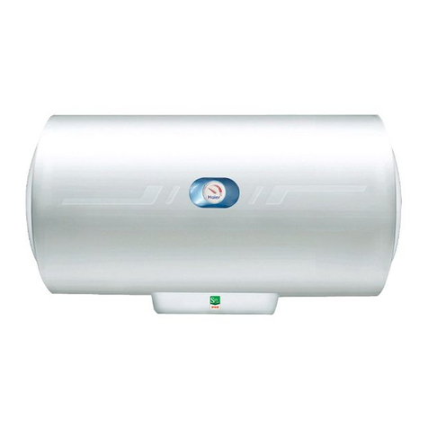
Rheem Heat Pump Water Heater
RHP-5207C Series
This water heater must be installed and serviced by a qualified person.
Please leave this guide with the householder.
2
Table of Content
Packing List ................ ... ......................................................................................... 2
Technical Specifications........... ................................................................................ 3
Installation.................................... .......................................................................... 4
Pipe connection............... .................. ..................................................................... 7
Wire connection................................. .. ................................................................. 11
Operation and usage.............................................................................................. 14
Maintenance................................... .......................................................................21
Common faults and solutions..................................................................................23
Replacement Parts................................................................. .................................26
Warranty Policy................................................................... ............ .......................27
Packing List
No
Name
Qty.
1
Heat Pump Water Heater
1
2
T&P relief valve
1
3
Non-return valve (6”)
1
4
Non-return valve (4”)
1
5
Drain valve
1
6
Extension tube (6”)
1
7
Wiring controller
1
8
Instruction manual
1
9
Warranty card
1
10
Qualification card
1
3
Technical Specifications
Model
RHP400-5207C
RHPD120-1505
RHPD150-1505
Power Supply
220V~50Hz
IP rating
IPX4
HP heating capacity (W)
5250
HP heating power/current input (W/A)
1250/5.7
Auxiliary electric heating rated power/ current (W/A)
3600/16.4
Maximum power/current input (W/A)
5500/25
Water heating capacity (L/h)
113
Refrigerant (charging amount: kg)
R134a (1.38)
Heat pump maximum water outlet temp. (℃)
70
Adjustable temperature range (℃)
35~75
Water side
Heat exchanger
Microchannel
Tank capacity(L)
(L)
400
120
150
Tank inlet/outlet/return water inlet connection
Rp3/4" (DN20)
Relief valve connection
Rp3/4" (DN20)
Circulating pump water inlet/outlet
Rp1/2" (DN15)
Maximum Pressure(MPa)
0.85
Air side
Heat exchanger type
Internal thread tube with
hydrophilic aluminum foil
Air inlet/outlet
Side/Front
Dimension
Length(mm)
740
Width(mm)
960
1475
1725
Height(mm)
1950
Weight - Empty(kg)
180kg
Weight - Full(kg)
580kg
Nominal conditions: environment dry bulb 20℃, wet bulb 15℃; Water inlet temp. 15℃,
outlet temp. 55℃
4
Dimension
Installation
◼Installation location
Do not install this water heater in a place where freezing may occur.
The water heater should be installed as close as possible to the hot water point with the
highest frequency of use.
There should be enough clearance around the water heater so that the entire unit can be
removed for repair or replacement if necessary. The electrical junction box and T&P relief
valve should be oriented for easy maintenance, and the nameplate should be easy to read.
The water heater should be installed on the floor to ensure that it is placed vertically and
avoid tilting. The building must be able to withstand the total weight of the water heater
after being filled with water without severe vibration.
5
◆The water heater should be placed on a refractory base with a height of not less than
50mm, and there should be a high temperature resistant floor drain with unobstructed
drainage near the base to prevent damage to other facilities in case the water heater or
pipeline leaks.
The installation location should be well ventilated, no obstacles that hinder the wind in
and out, and should not be exposed to rain and direct sunlight.
The water heater should be installed at location where its running noise and exhaust will
not affect the neighbors.
Make sure there is no leakage of flammable and corrosive gas at the installation location;
no oily smoke and dust; no or only small fluctuations of power supply voltage.
◼Installation Clearance
6
◼Installation Precautions
Wiring work must be done by a qualified electrician and must meet electrical safety
requirements. When the user needs to install and move, please contact the company's
after-sales service center for professional help. DO NOT install and shift it by yourself. Otherwise,
the company will not be responsible for any damage and failure caused and warranty of water
heater will be void.
(C ≤30°)
Warning: If the water heater is installed on the roof of building that is vulnerable to
lightning strikes, the water heater must be protected by lightning protection facilities!
Note: After the machine is in place, be sure to let the water heater stand for more than
30 minutes before turning on the power!
Note: Please transport the water heater according to
the state when it leaves the factory. Do not move the
water heater at an angle of more than 30°, let alone
place the machine vertically, and do not disassemble or
assemble it yourself!
7
Pipe Connection
◼Pipe connection diagram
◼Connection Instruction
⚫Material Requirements
Because the water heater and its piping system will bear pressure from tap water, all
water-side pipes must be made of temperature-resistant, pressure-resistant, and
corrosion-resistant metal or new-type plastic material. Pressure resistance performance of
the pipes must not be lower than the relief pressure of the T&P valve, while the
temperature resistance must not be lower than 99°C.
⚫Cold/Hot water pipe connection
1) Connection size: Rp 3/4"
Note: The water heater has a hot water pipe for the outlet connector
and a joint bushing on the inlet connector. These devices are
installed when the water heater leaves the factory and must not
be removed or damaged during installation. When the threaded
joint is screwed in, these devices will naturally be installed to the
correct depth.
8
2) Pipeline Size
To ensure the best performance, the pipe size should be selected according to the specific
installation needs. The following are the recommended pipe sizes.
Hot water pipe: Main pipe –Rp 3/4" (20mm)
Cold water pipe: The size of the cold-water pipe should be the same or larger than the size
of the hot water pipe used.
3) Cold water connection
The cold-water inlet is at lower part of the water heater and should be directly connected
with tap water. As shown in the figure, first connect a shut-off valve, then connect a
non-return valve on the side close to the heater, and finally connect a union.
If supply water pressure exceeds the rated max. pressure (680 kPa) as stipulated in the
label, a pressure limiting valve shall be connected after the non-return valve. If supply
water quality does not meet the specific water quality requirements, an expansion control
valve shall be used.
4) Hot water connection
The hot water supplied by the water heater has a relatively high temperature and cannot
be used directly for washing. It must be mixed with cold water. Therefore, the cold and hot
water mixing valve should be installed at the hot water use point.
If the hot water outlet of the water heater is too far away from the hot water use point
(more than 12 meters), it is recommended that the hot water pipe be insulated with heat
insulating materials to reduce the waste of hot water and electricity.
5) Water supplied by tank
If cold water is supplied by tank on the top floor, be noted that cold water connection
should meet the following requirements:
The tank shall be at least 1m higher than the highest hot water outlet. If the distance
between the bottom of the domestic tank and the highest hot water outlet is less than 5
meters, precaution should be taken into consideration to avoid air locks in the hot water
pipe. The shut-off valve in cold water pipeline shall be changed to gate valve, which shall
be fully open to ensure the full flow of cold water inlet.
9
⚫Condensation drainpipe connection
The water heater is equipped with a condensation drain hose, one end of which is
connected to the condensation drain and another end to the floor drain. To keep the water
pipe drainage unobstructed, there should be no bends or distortion.
◼Installation of T&P Relief Valve
The temperature and pressure relief (TPR) valve is act as a safety device, which can keep
system pressure at a safe level by discharging hot water to reduce pressure and lower
down system temperature when detecting system pressure exceeds rated value (850 kPa).
If water temperature is heated up to 93°C, the temperature sensing device will trigger the
TPR valve for hot water discharging and cold water will be entering to cool down the
system and reduce pressure. The discharge pipe connected to the relief valve should be
installed in a frost-free environment in a continuous downward manner, making sure water
can flow out freely; and the discharge pipe should be kept open to the atmosphere.
Specification of the TPR valve is 3/4″ × 125PSI (850 kPa).
◆Take out the T&P relief valve, make sure that the probe is not bent. Inspect the
operation lever and the flexibility of the handle.
◆Wrap the thread with PTFE, do not let the PTFE to go beyond the end of the thread;
screw the T&P valve into the installation hole, and make sure the valve drain outlet is
facing down.
◆Connect a DN20 drainpipe from the drain outlet of the TPR valve to floor trap. It is
strictly forbidden to install a valve on the drainpipe, and the total length of the pipe
shall not exceed 9 meters while the right-angle bend shall not exceed 3.
◆If the drainpipe is too long, to facilitate disassembly, a live connection can be
connected near the outlet of the TPR valve.
Warning: Regardless of the water supply method, the non-return valve
on the cold-water inlet pipe must be installed correctly, otherwise the
water heater or its parts might be damaged.
10
Warning: Drainpipe of the T&P relief valve shall be installed in
forest-free environment and kept inclined downwards. The outlet of the
drainpipe should not be blocked at any time, and it should be kept in
contact with the atmosphere, and make sure the discharged hot water
will not endanger people safety or cause property damage.
11
Wiring connection
◇The power supply for the water heater is single-phase AC with rated voltage 220V ~50Hz. The
wiring diagram is as below:
◼Precautions
● A specific power supply must be provided for the water heater, whose maximum voltage
fluctuation shall be within 90%-110% of the rated voltage.
● Wiring works must be perform by those skilled in this art and must be comply with
electric safety requirements.
● Grounding measures must be reliable, otherwise fire accident or electric shock may
occur.
●Power and signal cable must be well and properly arranged. No interference between
strong and weak power. Cables shall not contact with connection tube and valve.
12
● Power cable outside the unit must be well protected to prevent any hand contact or
electric shock even contacted (use tactile double insulated cable or provide insulation
protection for normal power cables).
◼Power specifications
Power
Cable diameter
(plastic insulation and wire case)
Air switch
capacity (A)
Leakage protector
Phase line
Zero line
Grounding
line
220V~50Hz
≥4
≥4
≥4
30
30mA (below 0.1 sec)
◼Power cable connection
● Select proper power cable as per Power Specification Sheet
● Dismantle the cover as figure on right side
●Connect the wire as figure below
13
Wire controller installation
◼Precautions
●Wire controller shall not be installed at where flammable gas leakage may occur. Fire
accident will be caused if the leaked flammable gas is stagnated around the wire controller.
● Wire controller shall not be installed near where oil, steam or sulfide gas is stagnated,
otherwise product deformation may occur.
● Wire controller shall be installed in dry places with good ventilation condition and
indirect sunlight.
● Cares must be taken for dust proof. Do not touch electronic components in the
installation process, otherwise damage may occur.
● Wire controller is low-voltage circuit. Direct connection to 220V or 380V voltage is
strictly prohibited. Communication cable for controller shall not be arranged in same
conduit with strong wire. Distance between the conduit must be 300-500mm or above.
● Diameter of communication cable conduit shall exceed 20mm.
● No transition or extension connection shall be carried out in the middle of the
connecting line of the wire controller.
● Megohmmeter shall not be used for insulation inspection after wire controller is
connected.
● Dimension of wire controller: Length × Width × Height - 89×89×21mm
Warning: For your safety concern, the water heater must be equipped
with air switches and leakage protectors in accordance with the power
specifications. The power supply must be grounded properly! DO NOT
use the water heater if without proper grounding. If the power cord is
damaged, for your safety, it must be replaced by professionals from the
manufacturer, its maintenance department, or similar departments!
14
◼Installation
●Fix the base to installation position.
● Buckle the cover assembly.
● Insert the cable plug to interface.
Operation and Usage
Filling the Water Heater
1)Cut off power supply of the water heater
2)Turn on the nearest hot water tap to empty air in the system
3)Turn on cold water valve completely to fill the tank and pipes.
4)When there is water flowing out from the hot water faucet, it indicates the tank is full,
turn off the hot water faucet and check if there is any water leakage
⚫Air empty is a vital process. The process above must be strictly complied with to avoid
failure or error code.
⚫In case of water supply is cut off or waterway is modified, process above must be followed
to empty air.
Warning: Do not power up the water heater without confirming that it has
been filled with water and that the T&P relief valve is in place. Damage
caused by dry burn is not covered by the warranty. Scald may be caused if
water temperature exceed 50℃. Make sure water temperature is proper.
15
Water drainage
It is necessary to empty the water heater in case of maintenance or suspending using water
heater in winter season:
1)Cut off the power supply.
2)Turn off the cold-water supply valve.
3)Connect one end of hose to the drainage outlet and lead the other end to floor drain.
4)Turn on the nearest hot-water tap and drainage valve.
5)Keep the drainage valve open if the water heater will not be used for a long term.
★Controller instruction
1. Button Description
1)“ON/OFF” button: power “ON” and “OFF” the water heater.
2)“UP” and “DOWN” button: adjust the set temperature point.
3)“Mode” button: switch sequentially between “ECO”, “Electric heating” and “Instant
heating”
16
4)“Setting” button: set time and timing function.
5)“Cycle” button: control the open and close of waterway circulation.
2. Function description
1)ON/OFF
Switch on and off the water heater by pressing “ON/OFF” button
When the water heater is powered on, the controller switches on and starts self-check,
following by a “beep” sound and the display screen illuminating for 2 secs.
2)Water temperature setting
In switch-on status, press “UP” or “DOWN” arrow button to adjust water temperature
within the range of 35-75°C. The default set point is 65°C.
3)Mode Selection
① ECO mode (default mode)
Press “Mode” button and select “ECO” mode. the ECO icon will light up. Only heat pump
will operate.
Under this mode, only heat pump to be started for heating purpose when operation
conditions are satisfied; if operation conditions are not satisfied, the electric heating will
operate until water temperature reaches setting point and enter heat preservation status.
Under ECO mode, if timing function is activated, the water heater will not heat beyond the
timing period.
When it is detected heat pump or heating element is working, the “heat indicator” will light
up, otherwise it will extinguish.
② Electric heating mode
Press “Mode” button to enter electric heating mode. In this mode, only heating element
will be operate for heating.
When water temperature reaches setting point, the water heater enters heat preservation
status. Under this mode, if timing function is activated, the water heater will not heat
beyond the timing period.
When it is detected heating element is working, the “heat indicator” will light up, otherwise
17
it will extinguish.
③ Quick heating mode
Press “Mode” button to enter quick heating mode. In this mode, heat pump and heating
element will operate simultaneously.
In case heat pump operation condition is not satisfied, only electric heating will operate.
When water temperature reaches setting point, the water heater enters heat preservation
status. Under this mode, if timing function is activated, the water heater will not heat
beyond the timing period.
Particularly, under ECO and Quick heating mode, if there is failure of heat pump, the system
will automatically switch to electric heating. But the mode displayed will not change.
When it is detected heat pump or heating element is working, the “heat indicator” will light
up, otherwise it will extinguish.
4)Wi-Fi
① Wi-Fi network set-up
Power on the unit, press “ON/OFF” for 5 seconds to enter Wi-Fi network set-up status
(Wi-Fi icon will flash with 1Hz). If Wi-Fi is successfully set up, the indicator will light up. The
Wi-Fi network only needs to be set up at the first time. The detailed connection process is
illustrated in “Hi Rheem APP Quick Guide”
② Wi-Fi clocking function
Set the clocking period on APP and the water heater will heat and preservation in the
corresponding period. Beyond the set period, water heater will not operate.
5)Single circulation
Press “Zero-cold water” to activate or shut down the single circulation. Water pump will
start to operate within the valid duration of 60 mins (default) as the operation condition is
satisfied. After 60 mins, the single circulation will exit.
6)Timing cruise
Before activating timing cruise, system time needs to be calibrated. How to calibrate: press
the "Set" button to enter the parameter setting, the digital tube "88" flashes to display the
hour (the rest of the displays are all off), press "Up" or "Down" to adjust the hour, and the
18
hour can be adjusted in cycles from 0 to 23 to 0. After the hour is set, short press the "set"
button to confirm the hour and enter the minute setting (adjustable from 0 to 59 to 0, and
all other displays are off).
Long press “Zero-cold water” to activate timing cruise function. The timing period and
corresponding number will light up.
In the timing period, the water pump will start if temperature meets the operation
condition of water pump. Beyond the period, the water pump will not operate.
In particular, the longest time for water pump operation is 10mins, the mandatory break
time is 1min.
7)Anti-stuck for circulation pump
To prevent stuck of circulation pump, one-time circulation will start after 24h without any
operation. The circulation will stop after 5s.
8)Anti-Freeze Function (“On” by default)
Under the premise that the water heater is powered on, regardless it is in switch-on or off
status, the anti-freeze function will activate heating element and heating icon will be
lightened up when lower tank sensor detecting that the temperature is below 5°C (the
heating icon will be lightened up even if the water heater is in switch off status). Heating is
to be suspended until the water temperature of lower tank reaches 10°C and will be
restarted repeatedly when temperature descends below 5°C. Priority will be given to
normal heating operation in case of anti-freeze function and heating function co-exists.
9)Memory for Power-Failure
In the case of power-failure (power-outage or disconnection), the unit has a smart
auto-memory recall function. After power is back on, all the settings, including temperature,
mode and status will be restored to prior settings before power-failure.
Note: DO NOT disconnect power supply of the water heater when it is to
be operated in environment where ambient temperature will be below
2℃. If the power must be disconnected, please discharge all the water in
the tank in advance and make sure it is empty. Otherwise, Rheem will not
be responsible for any water heater failure and property loss caused.
19
10)Sterilization
To activate the one-time high-temperature sterilization function, ensure the water heater is
powered on. Press both “UP” and “Mode” button simultaneously for 5 seconds to enable
the sterilization function. The heating icon will be lightened constantly after flashing for 5
seconds indicating sterilization function is turned on. Once the water temperature is
reaches ≥80°C, the water heater will exit sterilization mode and automatically return to the
set mode. To manually exit the sterilization process at any time, simultaneously press both
“UP” and “Mode” button for 5 seconds. The sterilization function will be disabled, and the
display will return to normal status.
11)Hot Water Volume Display
The small circle bar is the indication for hot water volume display. The more circles lighted,
the more hot-water volume left.
20
Hot Water Usage
◆Under normal circumstances, the cold-water inlet shut-off valve should always be open,
and cold water will be automatically replenished when hot water is discharged.
◆During the heating process of the water heater, it is normal for the T&P relief valve to
discharge a small amount of hot water
◆In the event of a power failure, the stored hot water can still be used.
◆When the water supply is cut off, it is recommended to close the cold water shut-off valve
of the water heater to prevent water flowing back and emptying the tank due to failure of
the non-return valve, which can be reopened when the water supply is restored.
Turn off the water heater
If the water heater needs to be turned off for maintenance or long-time shutoff, please follow
the instructions below:
◆Cut off power supply of the water heater.
◆Turn off cold water and hot water shut-off valve.
Water quality
The water heater is applicable for water quality for most urban areas. Please refer to
detailed water quality requirement in Nation Standard CJ/T 206-2005 “Water quality standards
for urban areas”. Poor water quality will have a detrimental effect on the water heater and its
operation and /or life expectancy. If you are unsure of your water quality, information can be
obtained from your local water supply authority.
This water heater can be used in areas where the total dissolved solid content (TDS) in
water is less than 1000mg/L, but when TDS is more than 600 mg/L, it will accelerate the
consumption of power anode rod and shorten service life of the water heater.
Saturation index of water that is prone to scaling:
Note: If you do not need to use the water heater in winter in cold areas,
please empty the water in the tank in case freezing damage.
Warning: To prevent scald and burns, never let children use the hot water
faucet or take a bath by themselves; never leave children or disabled
people alone in the bathtub or under the shower head without care.

Other Rheem Water Heater manuals

Rheem 850 Series Technical Document

Rheem

Rheem 850 Series Technical Document

Rheem Water Heater User manual

Rheem

Rheem Water Heater User manual

Rheem Solaraide RS47-21BP User manual

Rheem

Rheem Solaraide RS47-21BP User manual

Rheem Ruud 120 Gallon User manual

Rheem

Rheem Ruud 120 Gallon User manual

Rheem 491 Technical Document

Rheem

Rheem 491 Technical Document

Rheem RT1000C6 Technical Document

Rheem

Rheem RT1000C6 Technical Document

Rheem PVG Setup guide

Rheem

Rheem PVG Setup guide

Rheem 872 Technical Document

Rheem

Rheem 872 Technical Document

Rheem RTE 3 Technical Document

Rheem

Rheem RTE 3 Technical Document

Rheem PowerVent Commercial Gas Water Heater User manual

Rheem

Rheem PowerVent Commercial Gas Water Heater User manual

Rheem Eclipse 6C318500A Technical Document

Rheem

Rheem Eclipse 6C318500A Technical Document

Rheem Everhot 2A1050M7 Operating instructions

Rheem

Rheem Everhot 2A1050M7 Operating instructions

Rheem Solar Premier Loline User manual
Rheem

Rheem Solar Premier Loline User manual

Rheem RTG-66DVN User manual

Rheem

Rheem RTG-66DVN User manual

Rheem Stellar Technical Document

Rheem

Rheem Stellar Technical Document

Rheem 54 KW User manual

Rheem

Rheem 54 KW User manual

Rheem 199,000 Btu/hr User manual

Rheem

Rheem 199,000 Btu/hr User manual
Rheem Low NOX User manual

Rheem

Rheem Low NOX User manual

Rheem Solaraide Series User manual

Rheem

Rheem Solaraide Series User manual

Rheem MHD75245 User manual

Rheem

Rheem MHD75245 User manual

Rheem RH-188 Series User manual

Rheem

Rheem RH-188 Series User manual

Rheem 265 series User manual

Rheem

Rheem 265 series User manual

Rheem 86VP6S Installation guide

Rheem

Rheem 86VP6S Installation guide

Rheem Rheem RTG-53DV User manual

Rheem

Rheem Rheem RTG-53DV User manual

Popular Water Heater manuals by other brands

GE PE30S09KAG Energy guide

GE

GE PE30S09KAG Energy guide

A.O. Smith 970 Series parts list

A.O. Smith

A.O. Smith 970 Series parts list

State Water Heaters SRGSS01806 Specification sheet

State Water Heaters

State Water Heaters SRGSS01806 Specification sheet

Noritz GQ-2857WX-F US installation manual

Noritz

Noritz GQ-2857WX-F US installation manual

A.O. Smith Gas Fired Tank-type Water Heater parts manual

A.O. Smith

A.O. Smith Gas Fired Tank-type Water Heater parts manual

Rinnai RUR98i Installation and operation manual

Rinnai

Rinnai RUR98i Installation and operation manual

Bradford White RG1PV40S Service manual

Bradford White

Bradford White RG1PV40S Service manual

Prisma 2.0 Technical documentation

Prisma

Prisma 2.0 Technical documentation

Western Global FuelCube FCP250 Operator's manual

Western Global

Western Global FuelCube FCP250 Operator's manual

Quietside DPW-099 user manual

Quietside

Quietside DPW-099 user manual

Bosch 715ES Service bulletin

Bosch

Bosch 715ES Service bulletin

Ariston RT45PE-VN manual

Ariston

Ariston RT45PE-VN manual

Rinnai R63LSe Operation and installation manual

Rinnai

Rinnai R63LSe Operation and installation manual

Ariston FAST EVO X ONT user manual

Ariston

Ariston FAST EVO X ONT user manual

Coleman 2302-A instruction manual

Coleman

Coleman 2302-A instruction manual

Bradford White UCG100H399 Service manual

Bradford White

Bradford White UCG100H399 Service manual

Noritz N-0751M-DVC installation manual

Noritz

Noritz N-0751M-DVC installation manual

Bradford White ULG275H763N-475 Installation/operation instruction manual

Bradford White

Bradford White ULG275H763N-475 Installation/operation instruction manual

manuals.online logo
manuals.online logoBrands
  • About & Mission
  • Contact us
  • Privacy Policy
  • Terms and Conditions

Copyright 2025 Manuals.Online. All Rights Reserved.