manuals.online logo
Brands
  1. Home
  2. •
  3. Brands
  4. •
  5. Rheem
  6. •
  7. Water Pump
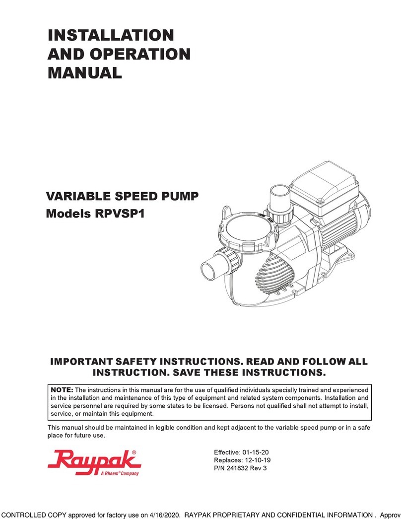
  8. •
  9. Rheem RAYPAK PROTEGE RPVSP Operating instructions

Rheem RAYPAK PROTEGE RPVSP Operating instructions

P/N 241844 Rev 2
E󰀨ective: 08-14-2020
Replaces: NEW
RAYPAK SERVICE INSTRUCTIONS
Scope
These kits provide the parts required to replace the
Di󰀨user, Impeller and Seal for the Protégé Variable-
Speed Pump (VSP).
Kit Parts
Kit Parts Included
018232F Di󰀨user with O-Ring
018233F Impeller, Impeller screw and O-ring
018234F 3/4" Mechanical seal, Flange O-ring, Flange,
M8 X 35 Screw with washer (Set of 4)
Required Tools
• Flat head screwdriver
• 5/8" rachet wrench
• Adjustable wrench
018232F
018233F
018234F
PROTÉGÉ VARIABLE-SPEED PUMP (VSP) MODEL RPVSP
KITS: 018232F, 018233F, 0182234F
DIFFUSER, IMPELLER, SEAL
DANGER – SHOCK HAZARD: Make sure electrical power to pump and heaters is
disconnected to avoid damage to components, potential serious personal injury or
death.
WARNING: Make sure water & power have been turned OFF before making any re-
pairs or service to the unit.
IMPORTANT NOTICE: These instructions are for the use of qualied individuals
specially trained and experienced in the installation and maintenance of this type of
equipment and related system components. Installation and service personnel are
required by some states to be licensed. Persons not qualied shall not attempt to in-
stall, service, or maintain this equipment.
2
Replacing Di󰀨user, Impeller and Seal
 ADANGER: ELECTROCUTION
OR ELECTRICAL SHOCK RISK.
DISCONNECT ELECTRICITY BEFORE
WORKING ON PUMP, OR SHOCK, BURN
OR ELECTROCUTION CAN RESULT.
Remove power from the pump by turning o󰀨 the breaker.
Death or serious injury to service people, pool users or
others due to electric shock could result from failure to
avoid the high danger risk.
1. Power must be in the OFF position in the breaker
panel as the unit is hard-wired directly into the power
panel, meaning that is the only way to cut power.
2. Allow the pump motor to cool down before servicing
the unit.
3. Close the water valves, if installed, to isolate the
pump from the system.
4. Separate pump motor and flange from pump volute
by removing the two outer bolts and then the two
outer bolts on the opposing side. Pull the motor and
flange back and away from the volute. See Figure 1.
Figure 1. Pump Separation, Bolt Location
5. Using a Phillips screwdriver, remove the three screws
holding the diffuser to the flange/seal plate, freeing
the diffuser for removal. See Figure 2.
Figure 2. Di󰀨user Plate Separation, Screw Location
6. Remove the impeller center screw using a 5/8 inch
socket wrench. NOTE – this screw is REVERSE
THREADED and can only be removed by turning
CLOCKWISE while holding the impeller stationary.
See Figure 3.
Figure 3. Impeller Bolt Removal
7. Removing the impeller requires holding the motor
shaft stationary while turning the impeller counter-
clockwise. A flat screwdriver must be inserted into the
slot in the end of the shaft at the rear of the motor.
An access hole is provided in the center of the rear
motor cover. While holding the shaft still with the
screwdriver, manually rotate the impeller counter-
clockwise to unscrew. See Figure 4.
Figure 4. Screwdriver Insertion Point
8. Remove the remaining four bolts holding the flange/
seal plate to the motor, and separate the two. See
Figure 5.
3
Raypak, Inc., 2151 Eastman Avenue, Oxnard, CA 93030 1-800-260-2758 Fax (805) 278-5468
Figure 5. Shaft Seal Removal
9. The mechanical shaft seal is a two-part device,
consisting of a larger, spring-loaded rubber sleeve
and a smaller white ceramic disc with a rubber outer
cover. See Figure 6 and Figure 7. At no time should
the contact surfaces of the two halves be touched
with bare hands or fingers, as this will contaminate
the surface. The disc is pushed into the indentation
in the center of the seal plate with the white ceramic
side facing outward, toward the impeller. Wetting
the rubber outer cover may be helpful. Do not use
lubricant. Press the disc completely into place until
it is fully seated and level. A clean rubber glove or
the rounded handle of a screwdriver may be used
to push the seal into place. The spring portion of the
seal is pushed on to the stem on the back side of
the impeller, again making sure bare hands do not
come in contact with the smooth surface of the black
ceramic point of contact.
Figure 6. Spring Loaded Seal
Figure 7. Ceramic Disc
10. Reattach the flange/seal plate to the motor with the
shaft protruding through the disc, and reinstall the
four bolts to secure.
11. Again, holding the motor shaft stationary with the
screwdriver as before, thread the impeller onto
the shaft, turning clockwise until tight. The spring
will compress and hold the two halves of the seal
together.
12. Using a small screwdriver, pry the old O-ring from
the slot on the diffuser, lubricate the new O-ring, and
install in the slot. See Figure 8.
Figure 8. Di󰀨user O-ring
13. Attach the diffuser to the flange/seal plate with the 3
provided screws.
14. Locate the existing large O-ring on the inside of the
flange/seal plate and replace with the new one, using
appropriate lubricant.
15. Rejoin pump motor and flange with the pump volute,
pushing forward until seated, and reattach with four
bolts. Tighten bolts by alternating across, turning
each one a few turns until they are all tight.
16. Open water valves, if installed, and make sure the
pump is filled with water.
17. Check for leaks.
18. Reconnect the electrical and turn on power.

This manual suits for next models

3

Other Rheem Water Pump manuals

Rheem UPS 20-60N Instructions for use

Rheem

Rheem UPS 20-60N Instructions for use

Rheem Classic Plus Series User manual

Rheem

Rheem Classic Plus Series User manual

Rheem 310 Series Operating instructions

Rheem

Rheem 310 Series Operating instructions

Rheem Raypak RPVSP1 User manual

Rheem

Rheem Raypak RPVSP1 User manual

Popular Water Pump manuals by other brands

ProMinent Sigma 2 S2Ca operating instructions

ProMinent

ProMinent Sigma 2 S2Ca operating instructions

CET PFP-14hpKHL-EM-MR instruction manual

CET

CET PFP-14hpKHL-EM-MR instruction manual

Desmi B114N Operation and maintenance instructions

Desmi

Desmi B114N Operation and maintenance instructions

SHURflo 9300 series installation instructions

SHURflo

SHURflo 9300 series installation instructions

Pfeiffer Vacuum DUO 10 MC operating instructions

Pfeiffer Vacuum

Pfeiffer Vacuum DUO 10 MC operating instructions

QED Well Wizard 1100 Series installation guide

QED

QED Well Wizard 1100 Series installation guide

Aqua HC997-1 Programming instructions

Aqua

Aqua HC997-1 Programming instructions

KSB RC Series instruction manual

KSB

KSB RC Series instruction manual

Pentair DELTA ENVIRONMENTAL D1P20-21 Installation and service manual

Pentair

Pentair DELTA ENVIRONMENTAL D1P20-21 Installation and service manual

VARO POWERPLUS POWEW67915 manual

VARO

VARO POWERPLUS POWEW67915 manual

Sundyne LMV-801 Instruction and operation manual

Sundyne

Sundyne LMV-801 Instruction and operation manual

GE UPK3 installation instructions

GE

GE UPK3 installation instructions

Grundfos NK instructions

Grundfos

Grundfos NK instructions

Verdemax 5981 user manual

Verdemax

Verdemax 5981 user manual

Graco Injecto-Flo II Single Line instructions

Graco

Graco Injecto-Flo II Single Line instructions

Pfeifer Vacuum XtraDry 150-2 operating instructions

Pfeifer Vacuum

Pfeifer Vacuum XtraDry 150-2 operating instructions

Elmo Rietschle C Series operating instructions

Elmo Rietschle

Elmo Rietschle C Series operating instructions

ASC SP008 instructions

ASC

ASC SP008 instructions

manuals.online logo
manuals.online logoBrands
  • About & Mission
  • Contact us
  • Privacy Policy
  • Terms and Conditions

Copyright 2025 Manuals.Online. All Rights Reserved.