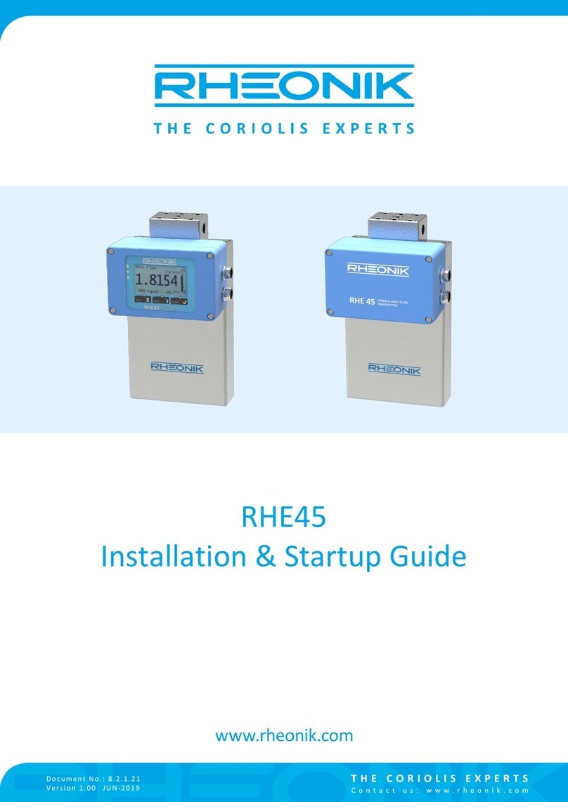
RHEONIK RHE42 User manual

RHE 42 Coriolis transmitter
User Manual

Rheonik Messtechnik GmbH
Rudolf-Diesel-Straße 5
D-85235 Odelzhausen
Germany
Tel + 49 (0)8134 9341-0
info@rheonik.com
Document No.: BA02RHE42202207
Version 04
November 2023

3 / 108
RHE 42 Coriolis transmitter
Foreword
Foreword
This installation guide contains important information regarding how to install, start up, and safely operate
the RHE42 Coriolis transmitter as intended together with an RHM Coriolis sensor. The German version of the
installation guide is the original installation guide. It supplements the information provided in the RHE 40
desktop reference. The RHE 40 desktop reference and further information are available to download from the
Rheonik Messtechnik GmbH website: ⮫
https://rheonik.com
.
Copyright
This installation guide is protected by copyright law. Any use that goes beyond the strict limits set by copy-
right law is forbidden and liable for prosecution without the prior consent of Rheonik Messtechnik GmbH. This
also applies to any reproduction, translation and microlming in addition to saving and editing in electronic
media. Any infringements will be liable for compensation!
Disclaimer
Rheonik Messtechnik GmbH accepts no liability for personal injury, damage to property or accidents caused
by the following:
■Failure to observe the installation guide
■Failure to observe the safety regulations
■Using the RHE42 Coriolis transmitter in an impermissible manner
Liability
Claims for compensation against Rheonik Messtechnik GmbH arising due to a breach of pre-contractual or
contractual obligations or tortious acts shall exist only in the case of intent or gross negligence on the part of
the seller, their representatives or vicarious agents.
If Rheonik Messtechnik GmbH breaches essential contractual obligations due to gross negligence, the extent
of the liability shall be restricted to the typically foreseeable loss. If performance is impossible or in the case
of default, the claims for compensation shall be restricted to reimbursement of the typically foreseeable loss.
If a vicarious agent of Rheonik Messtechnik GmbH acts in a grossly negligent manner, Rheonik Messtechnik
GmbH shall be liable to the extent of the typically foreseeable loss. The liability in the case of a breach
of essential contractual obligations and in the case of fraudulent intent on the part of the seller remains
unaected by this. In the case of physical injury or damage to well-being and health, the applicable statutory
regulations shall apply.
Other applicable documents
The following documents contain additional information regarding how to operate the RHE42 Coriolis trans-
mitter:
■RHE 40 desktop reference (operation manual)
■RHEComPro User Manual (operation manual)
■RHE 40 HART Manual (operation manual)
■RHE20/40 Addendum PID Controller (operation manual)
■RHE40 Addendum Data Logging (operation manual)
■RHE40 Addendum Precision Flow Analysis (operation manual)
■RHE40 Addendum Statistics (operation manual)
■RHE16/20/40 Modbus Map (list of Modbus registers)
■RHM Coriolis sensor (operation manual)
The documents are available to download from the Rheonik Messtechnik GmbH website: ⮫
http://rheonik.com
.

4 / 108
RHE 42 Coriolis transmitter
Foreword

5 / 108
RHE 42 Coriolis transmitter
Table of contents
Table of contents
1 About this guide. . . . . . . . . . . . . . . . . . . . . . . . . . . . . . . . . . . . . . . . . 7
1.1 General information. . . . . . . . . . . . . . . . . . . . . . . . . . . . . . . . . . 7
1.2 Target group. . . . . . . . . . . . . . . . . . . . . . . . . . . . . . . . . . . . . . . . 7
1.3 Storage. . . . . . . . . . . . . . . . . . . . . . . . . . . . . . . . . . . . . . . . . . . . 7
1.4 Declaration of Conformity. . . . . . . . . . . . . . . . . . . . . . . . . . . . 7
1.5 Symbols used in this guide. . . . . . . . . . . . . . . . . . . . . . . . . . . 8
2 Safety. . . . . . . . . . . . . . . . . . . . . . . . . . . . . . . . . . . . . . . . . . . . . . . . . . . 9
2.1 How warnings are structured and what they mean. . . . . . 10
2.2 Safety and associated safety measures. . . . . . . . . . . . . . . . 11
2.3 Personnel qualications. . . . . . . . . . . . . . . . . . . . . . . . . . . . . . 12
3 Intended use. . . . . . . . . . . . . . . . . . . . . . . . . . . . . . . . . . . . . . . . . . . . . 13
3.1 Intended use RHE42. . . . . . . . . . . . . . . . . . . . . . . . . . . . . . . . . 13
3.2 Impermissible use. . . . . . . . . . . . . . . . . . . . . . . . . . . . . . . . . . . 13
4 Product description. . . . . . . . . . . . . . . . . . . . . . . . . . . . . . . . . . . . . . 15
4.1 Model code. . . . . . . . . . . . . . . . . . . . . . . . . . . . . . . . . . . . . . . . . 18
4.2 Protection classes and safety areas (explosion protec-
tion). . . . . . . . . . . . . . . . . . . . . . . . . . . . . . . . . . . . . . . . . . . . . . . 20
5 Transportation, storage, scope of delivery. . . . . . . . . . . . . . . . 21
6 Installing the RHE42 Coriolis transmitter. . . . . . . . . . . . . . . . . 23
6.1 Installing the RHE42 Coriolis transmitter onto a wall or
mounting plate (RHE42-R*). . . . . . . . . . . . . . . . . . . . . . . . . . . 23
6.2 Installing the RHE42 Coriolis transmitter on a pipe
(RHE42-R*). . . . . . . . . . . . . . . . . . . . . . . . . . . . . . . . . . . . . . . . . 25
7 Connecting the RHE42 Coriolis transmitter. . . . . . . . . . . . . . . 26
7.1 Connecting the RHE42 Coriolis transmitter to the RHM
Coriolis sensor (RHE42-R*). . . . . . . . . . . . . . . . . . . . . . . . . . . 26
7.2 Connecting the power supply, inputs/outputs and signal
cables to on the RHE42 Coriolis transmitter. . . . . . . . . . . . 31
7.3 Wiring diagrams for the power supply, RS485 and
Modbus TCP. . . . . . . . . . . . . . . . . . . . . . . . . . . . . . . . . . . . . . . . 37
7.3.1 Connecting the power supply. . . . . . . . . . . . . . . . . . . . . . 37
7.3.2 Connecting the RS485 interface. . . . . . . . . . . . . . . . . . . . 37
7.3.3 Connecting the Modbus TCP interface. . . . . . . . . . . . . . . 39
7.3.4 Connecting the Foundation Fieldbus / Probus inter-
face. . . . . . . . . . . . . . . . . . . . . . . . . . . . . . . . . . . . . . . . . . . . . 40
7.4 Wiring diagrams for non-intrinsically safe inputs and out-
puts. . . . . . . . . . . . . . . . . . . . . . . . . . . . . . . . . . . . . . . . . . . . . . . 41
7.4.1 Connecting non-intrinsically safe analogue outputs. . . 41
7.4.2 Connecting non-intrinsically safe digital outputs. . . . . 42
7.4.3 Connecting non-intrinsically safe digital inputs. . . . . . . 43
7.4.4 Connecting a non-intrinsically safe HART interface. . . 44

6 / 108
RHE 42 Coriolis transmitter
Table of contents
7.5 Wiring diagrams for intrinsically safe inputs and outputs. 45
7.5.1 Connecting intrinsically safe analogue outputs. . . . . . . 45
7.5.2 Connecting intrinsically safe digital outputs. . . . . . . . . . 46
7.5.3 Connecting intrinsically safe digital inputs. . . . . . . . . . . 46
7.5.4 Connecting an intrinsically safe HART interface. . . . . . 47
8 Start-up. . . . . . . . . . . . . . . . . . . . . . . . . . . . . . . . . . . . . . . . . . . . . . . . . 49
8.1 Function of the keys on the RHE42 Coriolis transmitter. . 49
8.2 Operation. . . . . . . . . . . . . . . . . . . . . . . . . . . . . . . . . . . . . . . . . . . 51
8.3 Initial start-up. . . . . . . . . . . . . . . . . . . . . . . . . . . . . . . . . . . . . . . 53
8.3.1 Calibrating the zero point. . . . . . . . . . . . . . . . . . . . . . . . . . 54
8.3.2 Changing the ow direction. . . . . . . . . . . . . . . . . . . . . . . . 56
8.3.3 Reading out the IP address. . . . . . . . . . . . . . . . . . . . . . . . . 58
8.3.4 Setting up the RS485 interface. . . . . . . . . . . . . . . . . . . . . 59
8.3.5 Setting the units of measurement. . . . . . . . . . . . . . . . . . . 61
8.3.6 Conguring analogue outputs. . . . . . . . . . . . . . . . . . . . . . 63
8.3.7 Conguring digital outputs. . . . . . . . . . . . . . . . . . . . . . . . . 66
8.3.8 Conguring digital inputs. . . . . . . . . . . . . . . . . . . . . . . . . . . 69
8.3.9 Performing an output test. . . . . . . . . . . . . . . . . . . . . . . . . . 72
9 Operation, operating modes, using the device. . . . . . . . . . . . 75
9.1 Resetting the mass ow and volume meters. . . . . . . . . . . . 75
9.2 Adjusting the display settings. . . . . . . . . . . . . . . . . . . . . . . . . 76
9.3 Setting the lter. . . . . . . . . . . . . . . . . . . . . . . . . . . . . . . . . . . . . 78
10 Servicing, maintenance. . . . . . . . . . . . . . . . . . . . . . . . . . . . . . . . . . 81
10.1 Reading out the Assurance Factor and displaying the
Assurance View. . . . . . . . . . . . . . . . . . . . . . . . . . . . . . . . . . . . . 81
10.2 Reading out the zero point. . . . . . . . . . . . . . . . . . . . . . . . . . . 82
11 Displaying errors. . . . . . . . . . . . . . . . . . . . . . . . . . . . . . . . . . . . . . . . . 85
12 Technical data. . . . . . . . . . . . . . . . . . . . . . . . . . . . . . . . . . . . . . . . . . . 91
13 Returns and disposal. . . . . . . . . . . . . . . . . . . . . . . . . . . . . . . . . . . . . 93
14 Appendix A: Ex-Safety Instructions
(product approval information). . . . . . . . . . . . . . . . . . . . . . . . . . . 95
15 Appendices. . . . . . . . . . . . . . . . . . . . . . . . . . . . . . . . . . . . . . . . . . . . . . 105

7 / 108
RHE 42 Coriolis transmitter
About this guide
1 About this guide
1.1 General information
This installation guide contains important information regarding how to
install, start up, and safely operate the RHE42 Coriolis transmitter as
intended. Carefully read the information in this installation guide before
starting any work with or on the RHE42 Coriolis transmitter, and make
sure you have understood everything.
1. Please familiarise yourself with the information in this installation
guide.
2. Observe the safety instructions and warnings in this installation
guide.
1.2 Target group
This installation guide is aimed at operating personnel and at anyone
who has been tasked with the installation and start-up work by the
operating personnel.
1.3 Storage
This installation guide is an essential part of the RHE42 Coriolis trans-
mitter and must be stored such that it remains accessible to personnel
at all times.
1.4 Declaration of Conformity
The versions of the RHE42 Coriolis transmitter described in this instal-
lation guide comply with the applicable standards and guidelines/direc-
tives.

8 / 108
RHE 42 Coriolis transmitter
About this guide
1.5 Symbols used in this guide
In this installation guide, sections containing particularly important
information are identied in line with the type of information they con-
tain, e.g. instructions, lists or references.
Symbol Meaning
Instruction; step in a process
If you need to perform several steps one after the
other, they will be numbered based on their chrono-
logical sequence. Instructions that consist solely of a
single step are not numbered.
Result; outcome of a step
Lists of entries in no particular order
References to gures, sections and chapters
This symbol indicates useful additional information.

9 / 108
RHE 42 Coriolis transmitter
Safety
2 Safety
To ensure that the RHE42 Coriolis transmitter is operated safely and
as intended, it is essential to familiarise yourself with the basic safety
instructions and safety regulations. It is also essential to comply with
the rules and regulations on accident prevention that apply at the
installation location.
This installation guide contains important information regarding how to
safely operate the RHE42 Coriolis transmitter as intended. Carefully read
the information in this installation guide before starting any work with or
on the RHE42 Coriolis transmitter, and make sure you have understood
everything.

10 / 108
RHE 42 Coriolis transmitter
Safety
DANGER: Hazard with a high
risk and that will result in
death or serious injury if not
prevented.
WARNING: Hazard with a mod-
erate risk and that may result
in death or serious injury if not
prevented.
CAUTION: Hazard with a low
risk and that may result in
slight or moderate injury if not
prevented.
ATTENTION (NOTE): Risk of
damage to property if informa-
tion is not observed.
2.1 How warnings are structured and what they mean
When performing dierent types of work either with the or on the
RHE42 Coriolis transmitter, the personnel carry out steps that could
entail hazards. These steps are therefore preceded by a warning.
Warnings are always structured as follows:
■Warning symbol
■Signal word:
–DANGER
–WARNING
–CAUTION
–ATTENTION
■Description of the type of hazard and how it arises
■Description of the potential consequences of disregarding the
hazard
■Description of measures for preventing the hazard
DANGER
Type of hazard and how it arises!
Potential consequence(s) of disregarding the hazard.
−List of measures for preventing the hazard
WARNING
Type of hazard and how it arises!
Potential consequence(s) of disregarding the hazard.
−List of measures for preventing the hazard
CAUTION
Type of hazard and how it arises!
Potential consequence(s) of disregarding the hazard.
−List of measures for preventing the hazard
NOTICE
Type of hazard and how it arises!
Potential consequence(s) of disregarding the hazard.
−List of measures for preventing the hazard

11 / 108
RHE 42 Coriolis transmitter
Safety
For your safety
2.2 Safety and associated safety measures
DANGER
Risk to life if the information in this installation
guide is not observed!
If the information in this installation guide is not observed,
this will result in serious injury or death.
−Read and observe the information in this installation
guide before working either with the or on the RHE42
Coriolis transmitter.
−Take the safety instructions and warnings seriously
and follow the measures for preventing the hazard.
−Work carefully in order to prevent accidents resulting
in personal injury or damage to property.
−Keep the installation guide safe and make it available
to anyone working either with the or on the RHE42
Coriolis transmitter.
DANGER
Risk to life due to explosive dust and gas atmos-
pheres igniting!
When working in hazardous areas there is a risk that
explosive dust and gas atmospheres will be ignited by
sparks or naked ames.
−Have work in hazardous areas performed only by
trained and instructed specialist personnel.
−Observe any country-specic guidelines that apply to
work performed in hazardous areas.
■Explosion protection in areas with explosive dust and gas
atmospheres
Explosive dust and gas atmospheres can cause major explosions
and re.
–Please observe the information concerning explosion protection
in Appendix A, see: ⮫
Chapter 14 ‘Appendix A: Ex-Safety Instruc-
tions (product approval information)’ on page 95
.
–In hazardous areas, only use the RHE42 Coriolis transmitter in
conjunction with intrinsically safe RHM Coriolis sensors. The clas-
sication can be found on the type label on the RHM Coriolis
sensor.
–The RHE42 Coriolis transmitter must be installed and maintained
in accordance with the applicable standards governing electrical
installations in hazardous areas.
–The connecting cable (ARHE-Cx) between the RHM Coriolis
sensor and RHE42 Coriolis transmitter is intrinsically safe.
–The connecting cable (ARHE-Cx) must not exceed 20 m in length.
–The connecting cable (ARHE-Cx) has been specied for a temper-
ature range of -50 to +105°C. Avoid any temperatures higher than
this. Temperatures of below -50°C are permitted if the connecting
cable (ARHE-Cx) has been routed in a protective conduit.

12 / 108
RHE 42 Coriolis transmitter
Safety
–If the RHE42 Coriolis transmitter has been installed in a haz-
ardous area, do not open it whilst it is energised.
–Observe all national regulations governing how to install, maintain
and repair instruments located in hazardous areas.
■Modications, attachments and conversions
Any modications to or attachments and conversions on the RHE42
Coriolis transmitter may make the safety devices less eective or
entirely ineective, resulting in unforeseeable hazards.
–Do not carry out any technical modications or extensions on the
RHE42 Coriolis transmitter.
■Risk of injury from slipping, tripping or falling when carrying
out installation work!
There is a risk of serious injury from slipping on or tripping over
electrical cables, supply lines, and tools that are lying around.
–Make sure that nobody could trip over or fall as a result of the
electrical cables when carrying out installation work.
–Route electrical cables and supply lines such that nobody could
slip on or trip over them and fall.
2.3 Personnel qualications
NOTICE
Damage to property due to inadequately qualied
personnel!
All electrical work must only be performed by people
who have in-depth expertise in electrical engineering
(e.g. qualied electricians). These individuals must provide
evidence that they have the requisite expertise for per-
forming work on electrical systems and the associated
components (e.g. by having passed an examination) and
have been trained on the specic product(s) in question.
Mechanical work must only be performed by appropriately
qualied and trained personnel.
Task Party responsible Qualication
Installation work Operating personnel Engineer
Work on the electrical system Operating personnel Qualied electrician
Initial start-up, conguration of
parameters
Operating personnel Engineer
Dismantling work Operating personnel Engineer
Disposal Specialist waste dis-
posal company
Expert specialists who have received specic
training
Tab. 1: Personnel qualications

13 / 108
RHE 42 Coriolis transmitter
Intended use
3 Intended use
Rheonik Coriolis mass ow measuring instruments consisting of a
sensor (RHM), a transmitter (RHE), and in some cases, an intercon-
necting cable, are intended for measuring liquids and gases. The oper-
ator must ensure that the instrument is only used in a way that com-
plies with limitations and certications listed on the instrument type
plates. These limitations/certications include, but are not limited to:
■Pressure and temperature ranges
■Approval limits (e.g., explosion protection, pressure equipment direc-
tive)
■Suitability of the materials of construction in contact with the
process
The instrument must be installed, operated, and maintained in accord-
ance with the manufacturer's instructions and guidelines. The instru-
ment must not be modied or altered in any way that has not been
approved by the manufacturer or certication body. Regular inspections
and preventive maintenance should be carried out to ensure ongoing
safety and performance. Use not in accordance with the intended pur-
pose may impair and/or endanger safety.
3.1 Intended use RHE42
The RHE42 Coriolis transmitter displays the measured values for RHM
Coriolis sensors. It can display the mass ow of liquids and gases as
well as the medium density and medium temperature. In addition, the
RHE42 Coriolis transmitter is able to calculate variables such as the
volume.
Only install and operate the RHE42 Coriolis transmitter in locations with
the following ambient conditions:
■Ambient temperature -20 to +60 °C (optionally -40 to +65 °C), see
specication on type label:
Fig. 3
■Altitude of max. 3000 m above sea level
■Relative humidity of 10 to 95% (non-condensing)
■In shade; not exposed to direct sunlight
3.2 Impermissible use
The following are examples of impermissible use of the RHE42 Coriolis
transmitter (i.e. use contrary to its intended use):
■Using the RHE42 Coriolis transmitter in locations other than those
specied above.
■Using the device in life-support systems in the medical, motor
vehicle, aircraft, water craft or mining industries.

14 / 108
RHE 42 Coriolis transmitter
Intended use

15 / 108
RHE 42 Coriolis transmitter
Product description
RHE42-C* Coriolis transmitter
(compact version RHE42 Cori-
olis transmitter installed on
RHM Coriolis sensor)
4 Product description
Fig. 1: RHE42 Coriolis transmitter with RHM Coriolis sensor
1 RHE42 Coriolis transmitter
2 RHM Coriolis sensor
3 Type label
4 Display
5 key
6 key
7 key

16 / 108
RHE 42 Coriolis transmitter
Product description
RHE42-R* Coriolis transmitter
(remote installation)
Type label
Fig. 2: RHE42 Coriolis transmitter with bracket for installation on the wall
1 RHE42 Coriolis transmitter
2 Installation angle for installation on the wall or a pipe
3 Type label
4 Display
5 key
6 key
7 key
Fig. 3: Type label
1 Type label
2 CE for conformity / CSA for approval
3 Table with safety limits for the intrinsically safe inputs and outputs
A Product designation
B Model code
C Serial number

17 / 108
RHE 42 Coriolis transmitter
Product description
System information
DCustomer-specic tag number RHM Coriolis sensor
E Permissible power supply
F Permissible ambient temperature
G Housing classication
H Serial number of corresponding sensors RHM
I ATEX classication / CSA Zone marking USA
J ATEX certicate number / CSA Zone marking Canada
K IECEx classication / CSA Division marking
L IECEx certicate number / CSA certicate number
Abbrevia-
tion
Name
DRV Sensor drive
PU Pick-up of measured values
TE Temperature measurement
AO Analogue output
DO Digital output
DI Digital input
U0Maximum output voltage
I0Maximum output current
P0Maximum output power
L0Maximum external inductance
C0Maximum external capacitance
UiMaximum input voltage
IiMaximum input current
PiMaximum input power
LiMaximum internal inductance
CiMaximum internal capacitance
FF FISCO eld device Foundation Fieldbus
Tab. 2: Abbreviations on the type label
A Coriolis ow meter or a Coriolis ow meter for hazardous areas
(optional) consists of the following components:
■RHM Coriolis sensor
■RHE42 Coriolis transmitter with built-in barrier
■Connecting cable (ARHE-Cx) (already installed on the RHE42 Coriolis
transmitter ex works) (only for the RHE42-R* versions)
The RHM Coriolis sensors are optionally available as intrinsically safe
versions. They can be installed in zone 0, 1 or 2, as well as in 20, 21
or 22, depending on their certication. Versions suitable for Div. 1 and

18 / 108
RHE 42 Coriolis transmitter
Product description
2 are available for the American market. Detailed information on the
protection classes and safety areas is provided here: ⮫
Chapter 4.2
‘Protection classes and safety areas (explosion protection)’ on page 20
.
4.1 Model code
RHE42- xx D1- xx xx
-
xx xx
-
xxx
Housing IP65/Type 4 (indoor and outdoor use) with
■3 m connecting cable (ARHE-Cx) and no “Human-Machine
Interface” (HMI) display and input device
RB
■10 m connecting cable (ARHE-Cx) and no HMI RC
■3 m connecting cable (ARHE-Cx) and with HMI RD
■10 m connecting cable (ARHE-Cx) and with HMI RE
Housing IP65/Type 4 (installed directly on the RHM Coriolis sensor)
■No HMI C1
■With HMI CD
Power supply
12 - 24 V DC ±10% D1
Software package
■Advanced diagnostic package (Assurance Factor) AF
■Package for legal metrology CT
■Multi-functional measurement package DO
■Package for the fastest signal processing FR
■Oil and gas function package OG
■Mass ow measurement package SO
Digital inputs and digital/analogue outputs (not intrinsically safe)
■Analogue outp. (a/p) 1x, dig. outp. 2x, dig. inp. 1x, RS 485
(Modbus), HART communication
1H
■Dig. outp. 2x, dig. inp. 2x, RS 485 (Modbus) B1
■Analogue outp. (a/p) 1x, dig. outp. 2x, dig. inp. 1x, RS 485
(Modbus), Modbus TCP/IPv4, HART communication
EA
■Dig. outp. 2x, dig. inp. 2x, RS 485 (Modbus), Modbus TCP/IPv4 EB
■Analogue outp. (a/p) 1x, dig. outp. 2x, dig. inp. 1x, RS 485
(Modbus)
S1
■Analogue outp. (a/p) 2x, dig. outp. 2x, RS 485 (Modbus),
HART communication
S2

19 / 108
RHE 42 Coriolis transmitter
Product description
RHE42- xx D1- xx xx
-
xx xx
-
xxx
Digital inputs and digital/analogue outputs (intrinsically safe)
■Analogue outp. (p) 1x, dig. outp. 2x, HART communication,
RS 485 (Modbus – not intrinsically safe)
i1
■Analogue outp. (p) 2x, dig. outp. 1x, dig. inp. 1x, HART com-
munication, RS 485 (Modbus – not intrinsically safe)
i2
■Foundation Fieldbus FFH1 (FISCO), analogue outp. (p) 1x, dig.
outp. 1x, RS 485 (Modbus – not intrinsically safe)
F2
■Foundation Fieldbus FFH1 (FISCO), RS 485 (Modbus – not
intrinsically safe)
FF
■Probus PA, RS 485 (Modbus – not intrinsically safe) PA
■Probus PA, analogue outp. (p) 1x, dig. outp. 1x, RS 485
(Modbus – not intrinsically safe)
P2
Explosion protection
■ATEX/IECEx zone 1, 2, gas A1
■ATEX/IECEx zone 2, gas A2
■ATEX/IECEx zone 21, 22, dust AD
■ATEX/IECEx safe area AS
■CSA US-Can. class I, Div 1, 2 / zone 0, 1, 2 C1
■CSA US-Can. class I, Div 2 / zone 2 C2
■CSA US-Can. class I, Div 1, 2 / class I, zone 20, 21, 22 CD
■CSA US-Can. safe area CS
Performance certication
■None NN
■ABS approval for ship applications AB
■Custody transfer certication OIML-CS R117 R7
■Custody transfer certication OIML-CS R139 9R
Options
■None NNN
■Improved protection rating IP66-67/Type 6,
Ambient temperature -40 - + 65°C.
N67
■Settings lock switch (included in software package CT and
FR)
NNH
Tab. 3: Denition of model code

20 / 108
RHE 42 Coriolis transmitter
Product description
4.2 Protection classes and safety areas (explosion protection)
Order
code
Designation Area of application for
RHE42 Coriolis trans-
mitter
Area of application
for RHM Coriolis
sensor
Certied
according
to/by
A1 II 2(1)G Ex db eb [ia Ga] IIC T6
Gb
Zone 1, 2; safe area Zone 0, 1, 2; safe
area
ATEX, IECEx
AA II 2(1)G Ex db eb [ia Ga] IIB T6
Gb
Zone 1, 2; safe area Zone 0, 1, 2; safe
area
ATEX, IECEx
A2 II 3(1)G Ex db ec [ia Ga] IIC T6
Gc
Zone 2; safe area Zone 0, 1, 2; safe
area
ATEX, IECEx
AB II 3(1)G Ex db ec [ia Ga] IIB T6
Gb
Zone 2; safe area Zone 0, 1, 2; safe
area
ATEX, IECEx
AD II 2(1)D Ex tb [ia Da] IIIC
T85°C Db
Zone 21, 22; safe area Zone 20, 21, 22; safe
area
ATEX, IECEx
AS II (1)G [Ex ia Ga] IIC and II (1)
D [Ex ia Da] IIIC
Safe area Zone 0, 1, 2; safe
area
ATEX, IECEx
C1 Class I, Div. 1, Group A, B, C &
D, T6
Class I; Div 1, 2; safe
area / zone 0, 1, 2; safe
area
Class I; Div 1, 2; safe
area; zone 0, 1, 2;
safe area
CSA / ETL
C2 Class I, Div. 2, Group A, B, C
& D, T6
Class I; Div 2; safe area /
zone 2; safe area
Class I; Div 1, 2; safe
area; zone 0, 1, 2;
safe area
CSA / ETL
CD Class II, Div 1, Group E, F and
G
Class II; Div 1, 2; safe
area; zone 20, 21, 22;
safe area
Class II; Div 1, 2; safe
area; zone 20, 21, 22;
safe area
CSA / ETL
CS [Ex ia Ga] IIC Safe area Class I; Div 1, 2; safe
area; zone 0, 1, 2;
safe area
CSA / ETL
Tab. 4: Overview of application areas
Table of contents
Other RHEONIK Transmitter manuals
Popular Transmitter manuals by other brands

Wireless Devices
Wireless Devices WD2 Operation manual

PR electronics
PR electronics 7501 series product manual

RKI Instruments
RKI Instruments 65-2649XL-HC-04 Operator's manual

Mitsubishi Electric
Mitsubishi Electric PAC-SF46EPA installation manual

Electia
Electia CS185 user guide

Litelink
Litelink VAT-1001 operating instructions

Comet
Comet W0810P Instructions for use

Monacor
Monacor JTS RU-850TB/5 instruction manual

BWI Eagle
BWI Eagle AIR-EAGLE SR PLUS manual

ABB
ABB TTF300 Commissioning instructions

Dwyer Instruments
Dwyer Instruments Magnesense II MS2 Specifications-installation and operating instructions

Camera Motion Research
Camera Motion Research Connex Mini quick guide