- -
PRESENTATION
The TxRail is a -wire DIN rail mount temperature transmitter. Microprocessor
based, it was designed for flexibility, accepting mV, Pt100 and a variety of
thermocouples as the input sensor. The TxRail delivers a scalable linear 4- 0mA
output current proportional to the sensor temperature. A user-friendly configuration
software is provided for parameter setup, including sensor type, temperature range,
filter, etc.
SPECIFICATIONS
Sensor input: User defined. The supported sensors are listed in table 01, along
with their maximum ranges.
Thermocouples: Types J, K, R, S, T, N and E, to IEC 60584 (ITS-90).
Impedance >> 1 M
Ω
Pt100: Excitation: 0.18 mA., or 3-wire connection (for -wire
sensors, tie terminals and 3 together).
α= 0.00385, according to IEC 60751(ITS-90).
Voltage: 0 a 50 mVdc.
Impedance >> 1 M
Ω
Sensor Type Range Minimum measurement span
Thermocouple K 0 to 1370 °C 100 °C
Thermocouple J 0 to 760 °C 100 °C
Thermocouple R 0 to 1760 °C 400 °C
Thermocouple S 0 to 1760 °C 400 °C
Thermocouple T 0 to 400 °C 100 °C
Thermocouple N 0 to 1300 °C 100 °C
Thermocouple E 0 to 7 0 °C 100 °C
Pt100 - 00 to 530 °C 40 °C
Voltage 0 to 50 mV 5 mV
Table 1 – TxRail input sensors
Output: -wire 4- 0 mA, linear with respect to the measured temperature.
Total accuracy: better than 0,3 % of the maximum range for thermocouples and
0, % for Pt100 and voltage;
Resolution: 0,004 mA (1 bits).
Response Time: < 100 ms;
Power supply: 18 to 30 Vdc, across the transmitter;
Maximum load (RL): RL (max.)= (Vcc – 1 ) / 0,0 [
Ω
]
where: Vcc= Power supply voltage
Operating Temperature: -40 to 85 °C
Humidity: 0 a 90 % RH
Electromagnetic compatibility: EN 50081- , EN 5008 -
No isolation between the sensor and the 4-20 mA loop.
Internal protection against polarity inversion.
Cold junction compensation for thermocouples.
Housing: ABS plastic. Dimensions: Refer to figure 4.
CONFIGURATION
Please check the configuration parameters programmed in theTxRail, using the
TxConfig software. A communication path needs to be established between the
TxRail and the serial port of a PC. The 1.5 m long TxConfig Interface is provided
for this purpose. Connect its DB9 end to the PC COMM port and the other end to
the transmitter as shown in Figure 1.
TxConfig interface has a buit-in electronic circuit to convert
voltage levels of the PC RS232 to acceptable levels. Never use
a different interface or cable to connect the product to the
RS232 port, or the device will be damaged. This damage is not
covered by product warranty.
Once configured, the transmitter is ready to be installed in the process.
Note: The TxConfig Interface and Software can be purchased separately from
Novus or one of its distributors. The latest release of this software can be
downloaded from our website www.novusautomation.com. Do not save the
TxConfig software into a file which contains accent marks. To install, run the
Tx_setup.exe and follow the instructions. To install de configurator, run the
Tx_setup.exe file.
Serial port configuration errors may occur when other devices are sharing the same
port (ex.: Palm Hot Synch). Close all serial port applications prior to using the
TxConfig software.
Transmitter
6
5
4
TxConfig Adaptor
Battery 9V
1
6
5
3
4
Figure 1 – Adaptor connections to the TxRail
The transmitter requires to be powered during the configuration. Depending on the
PC used, the power can be supplied by the serial port. To assure proper
communication, it is recommended to apply external power to the TxRail. The
TxConfig interface provides a 9 Vdc battery socket for powering the transmitter
during the configuration.
Do not use the battery if the transmitter is being powered by another supply or
connected to the process, as in Figure .
powered current loop
Transmitter
6
5
4
1 3
4
Figure – TxRail-TxConfig Adaptor wiring (loop powered). Terminal 5 is left opened.
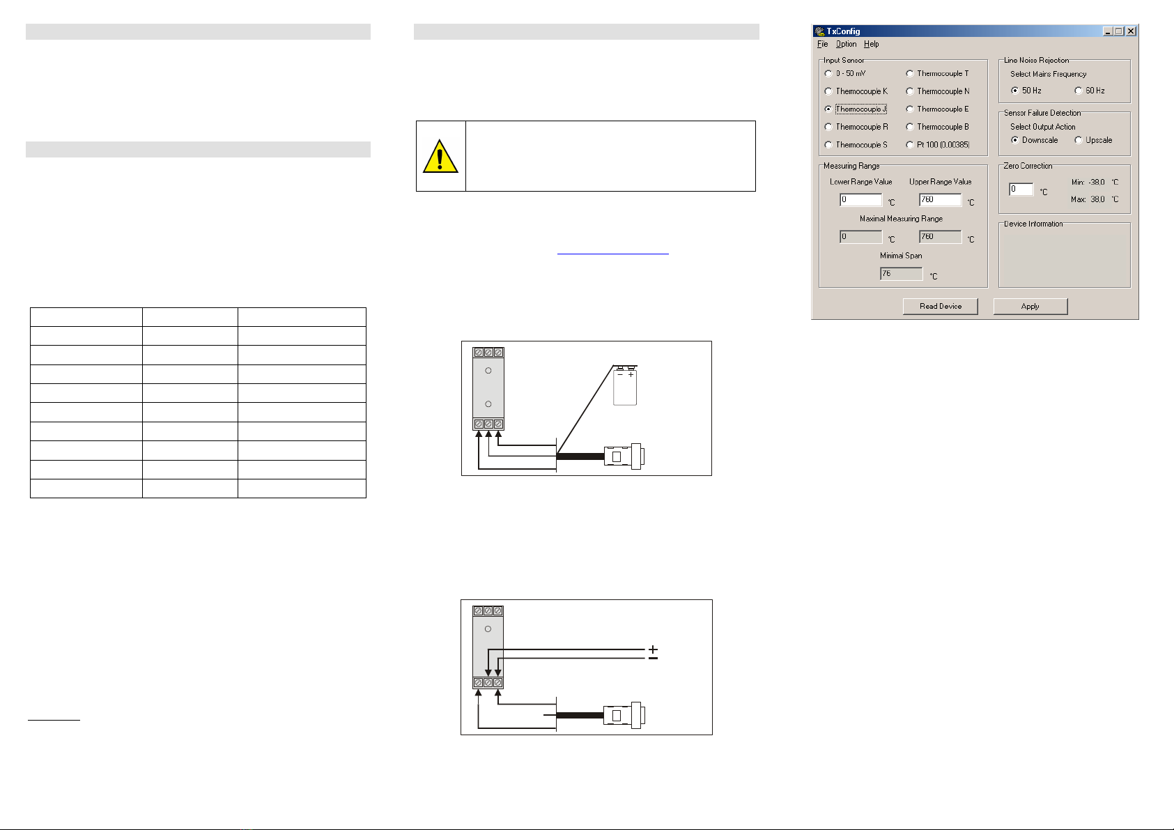
The TxConfig screen in shown in Figure 3. All user parameters can the seen and/or
modified by either typing a value or selecting among the available options. The help
menu provides further information about the software and the transmitter.
Figure 3 –TxConfig main screen
The fields in the screen mean:
1. Input Sensor: Choose the desired temperature sensor among the available
options.
. Measuring range: Defines the beginning and the end of the range.
Lower Range Value: sets the value of the input signal (temperature or mV)
associated to the 4 mA output.
Upper Range Value: sets the value of the input signal that will correspond to the
0 mA output
The values configured in these fields can not be beyond the sensor measuring
range. The minimum span value has to be observed as well (see Table 1).
3. Line Noise Rejection: The TxRail incorporates a digital filter to cancel the
induced noise from the 50 or 60 Hz systems. For better performance, select the
line frequency used in your country.
4. Sensor Failure Detection: establishes the transmitter output behavior (upscale
or down-scale) in the presence of a sensor fail.
5. ero Correction: Allows for small sensor corrections.
6. Read Configuration: Brings to the screen the current TxRail parameters
configuration.
7. Apply: Sends a new configuration to the transmitter.
8. Device Information:
The Device Information box contains relevant data concerning a particular TxRail
transmitter. Please pass along this information when contacting the technical
assistance department.
Note:
The factory default configuration is (unless otherwise specified or ordered):
Pt100 input, 0 to 100 °C
60 Hz filtering and upscale ( 0 mA) output for sensor fail.


