CYP CH-2602TXWPUS User manual

CH-2602TXWPUS
HDMI over HDBaseT Transmitter (PD)
with Optical Audio Return (OAR)
Operation Manual
Operation Manual


DISCLAIMERS
The information in this manual has been carefully checked and
is believed to be accurate. Cypress Technology assumes no
responsibility for any infringements of patents or other rights of third
parties which may result from its use.
Cypress Technology assumes no responsibility for any inaccuracies
that may be contained in this document. Cypress also makes no
commitment to update or to keep current the information contained
in this document.
Cypress Technology reserves the right to make improvements to this
document and/or product at any time and without notice.
COPYRIGHT NOTICE
No part of this document may be reproduced, transmitted,
transcribed, stored in a retrieval system, or any of its part translated
into any language or computer le, in any form or by any means—
electronic, mechanical, magnetic, optical, chemical, manual, or
otherwise—without express written permission and consent from
Cypress Technology.
© Copyright 2017 by Cypress Technology.
All Rights Reserved.
TRADEMARK ACKNOWLEDGMENTS
All products or service names mentioned in this document may be
trademarks of the companies with which they are associated.

SAFETY PRECAUTIONS
Please read all instructions before attempting to unpack, install or
operate this equipment and before connecting the power supply.
Please keep the following in mind as you unpack and install this
equipment:
• Always follow basic safety precautions to reduce the risk of re,
electrical shock and injury to persons.
• To prevent re or shock hazard, do not expose the unit to rain,
moisture or install this product near water.
• Never spill liquid of any kind on or into this product.
• Never push an object of any kind into this product through any
openings or empty slots in the unit, as you may damage parts
inside the unit.
• Do not attach the power supply cabling to building surfaces.
• Use only the supplied power supply unit (PSU). Do not use the PSU
if it is damaged.
• Do not allow anything to rest on the power cabling or allow any
weight to be placed upon it or any person walk on it.
• To protect the unit from overheating, do not block any vents or
openings in the unit housing that provide ventilation and allow for
sufcient space for air to circulate around the unit.
REVISION HISTORY
VERSION NO. DATE (DD/MM/YY) SUMMARY OF CHANGE
RDV1 26/08/16 Preliminary release
RDV2 22/03/17 Separation to 2 manuals

CONTENTS
1. Introduction......................................................1
2. Applications.....................................................1
3. Package Contents ..........................................1
4. System Requirements......................................2
5. Features............................................................2
6. Operation Controls and Functions.................3
6.1 Front Panel ................................................. 3
6.2 Rear Panel.................................................. 5
6.3 IR Cable Pin Assignment........................... 6
7. Connection Diagram ......................................7
8. Specications ..................................................8
9. Acronyms .........................................................9

1
1. INTRODUCTION
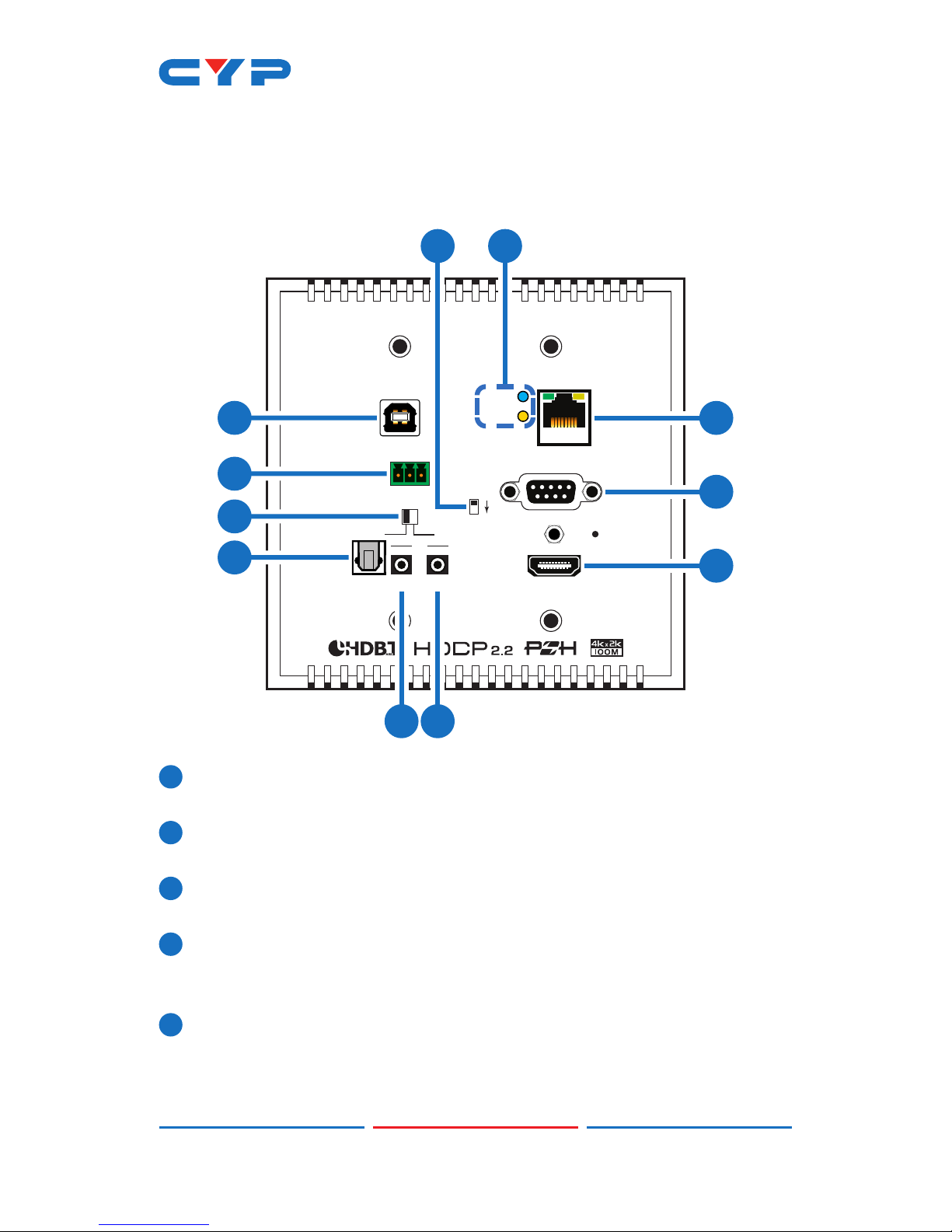
This HDBaseT 2.0 Transmitter can send uncompressed UHD video
and audio to a compatible Receiver over a single Cat.5e/6/7 cable
up to 100m. It has the added benet of extending control and
communication signals through the built-in Ethernet, USB, RS-232 and
IR ports. Independent external digital and analog audio transmission
capability gives users the extra convenience of additional audio
connections.
This unit's system supports connecting any standard USB 2.0 host to the
Transmitter, enabling the extension of the USB connection to up to 2
USB ports located on the Receiver, allowing it to act like a USB hub.
The integrated 48V PoH (Power over HDBaseT) support provides power
to the Transmitter (PD) from the Receiver (PSE), eliminating the need
for a separate power supply for the Receiver. The 2 gang US wallplate
mechanical design allows for exibility in mounting locations, saving
space and making your presentation space orderly and tidy.
2. APPLICATIONS
• Home theater extension and control
• Lecture hall display and control
• Showroom display and control
• Meeting room presentation and control
• Classroom display and control
3. PACKAGE CONTENTS
• 1×HDMI over HDBaseT Transmitter
• 1×IR Blaster Cable
• 1×Terminal Block (3-pin)
• 1×Operation Manual

2
4. SYSTEM REQUIREMENTS
• HDMI input source equipment such as media players, video game
consoles, PCs or set-top boxes.
• HDMI receiving equipment such as HDTVs, monitors or audio
ampliers.
• The use of “Premium High Speed HDMI” cables is highly
recommended.
• High quality Cat.5e/6/7 cables (Cat.6 or better is recommended).
5. FEATURES
• Supports the HDBaseT 2.0 specication over a single Cat.6/7 cable
up to 100m/328ft and Cat.5e cable up to 90m/295ft
• HDBaseT 5Play™ convergence: High-Denition (HD) Video and
Audio, 100BaseT Ethernet, 48V PoH, and Control (Bi-directional IR/
RS-232 pass-through)
• Transmitter (PD) is powered by 48V PoH from the Receiver (PSE)
• HDMI with 3D & 4K@60Hz (YUV 4:2:0) support, DVI 1.0 compatible
• HDCP 2.2 compliant
• 1×USB 2.0 Type B port
• Supports pass-through of HD audio formats: LPCM 2.0/5.1/7.1,
Bitstream, and HD Bitstream
• Supports optical audio sampling rates up to 48kHz
• Supports external analog and digital audio extension including
support for ARC (Audio Return Channel)
• Supports RS-232 baud rates from 110~115200bps
• 2 gang US wallplate mechanical design

3
6. OPERATION CONTROLS AND FUNCTIONS
6.1 Front Panel
IR
OPT. OUT OUT 1 IN 2
USB
L
AUDIO IN
R
UPDATE
ARC OUT
ON OFF
RS232 IN
LAN
HDMI IN
POWER
LINK
87
12
3
4
5
611
10
9
1POWER LED: This LED will illuminate when the device is receiving
power.
2UPDATE: This is reserved for rmware update use only. During
normal operation the dipswitch should be set to the right.
3USB: Connect to a PC or Laptop to extend the USB data
connection to the Receiver’s USB ports.
4AUDIO IN: Connect to the stereo analog output of a device such
as a CD player or PC to extend it to the Receiver’s AUDIO OUT L/R
port.
5ARC OUT ON/OFF: Enables or disables support for ARC (Audio
Return Channel) signals from the HDMI device connected to the
Receiver. When switched to ON the ARC audio will be routed to
both the HDMI input as well as the OPT. OUT port. When switched

4
OFF no ARC audio will be passed.
Note: When ARC is enabled the maximum supported HDMI cable
length may vary. It is suggested to use cables under 2 meters long
to ensure the best audio quality.
6OPT. OUT: Connect to an audio receiver or powered speaker set to
reproduce the audio signal from the Receiver’s OPT. IN port.
7IR OUT 1: Connect to the provided IR Blaster to transmit IR signals to
devices within direct line-of-sight of the IR Blaster.
8IR IN 2: Connect to the provided IR Extender to extend the IR
control range of remotely located devices. Ensure that the remote
being used is within direct line-of-sight of the IR Extender.
9LAN: Connect to an Ethernet supporting device or to your local
network as appropriate. The yellow LED will illuminate to indicate a
successful LAN connection between the Transmitter and Receiver
and will blink to indicate a data transmission. The green LED will
illuminate when the connected Ethernet speed is 100Mbit/s.
10 RS-232 IN: Connect to a PC, laptop or other serial control device
for the extension of RS-232 signals to the Receiver.
11 HDMI IN: Connect to HDMI source equipment such as a media
player, game console or set-top box.

5
6.2 Rear Panel
CAT5e/6/7 OUT
1
1CAT5e/6/7 OUT: Connect to the Receiver unit with a single
Cat.5e/6/7 cable for transmission of all data signals. The yellow LED
will illuminate to indicate a successful data connection between
the Transmitter and Receiver. If the yellow LED blinks irregularly it
indicates a data link error. The green LED will illuminate to indicate
when PoH is active.

6
6.3 IR Cable Pin Assignment
3
2
1
IR Blaster
Power
IR Signal
NC
3
1
2
IR Signal
Power
Ground
IR Extender

7
7. CONNECTION DIAGRAM
TX
RX
7m3m 3m
60°
1.5m
60°
TX RXLR
DC 48V
+
-
OPT.
IN
POWERAUDIO OUTIR IN1IR OUT2 USBUSB UPDATERS-232 OUT
CAT5e/6/7 IN
HDMI OUTLAN
OPT.
IN
ARC
IN
IR
OPT.OUT OUT 1 IN 2
USB
L
AUDIO IN
R
UPDATE
ARC OUT
ON OFF
RS232 IN
LAN
HDMI IN
POWER
LINK
7m3m 3m
60°
1.5m
60°
DVD/Blu-ray Player
Internet
Connected
Router
AV Receiver
CAT5e/6/7
Cable
Powered Speakers
Power Supply
RS-232 Controlled
Device
Optical
Audio
Output
(OAR)
Analog
Stereo
Input
HDMI
Input
Analog
Stereo
Output
RS-232
IR In
IR Out
IR Out
IR In
Smart TV with
Optical Audio Output
HDMI Output, LAN
Connection & Optical
Audio Input (OAR)
USB
USB Peripherals
RS-232 Equipped
PC/Laptop
RS-232
USB
LAN

8
8. SPECIFICATIONS
Video Bandwidth 340MHz/10.2Gbps
Input Ports 1×HDMI, 1×USB 2.0 (Type B), 1×Stereo
Audio (Terminal Block), 1×LAN (RJ45),1×IR
Extender (3.5mm), 1×RS-232 (9-pin D-sub)
Output Ports 1×Cat.5e/6/7, 1×Optical Audio (TOSLINK),
1×IR Blaster (3.5mm)
Supported Resolutions 480i@60Hz - 4K@60Hz (4:2:0, 8-bit)
VGA@60Hz - WUXGA@60Hz (RB)
HDMI Cable Length 10m (1080p@60Hz, 12-bit)
5m (4K@60Hz, 4:2:0, 8-bit)
Cat.5e Cable Length 100m (1080p@60Hz, 12-bit)
90m (4K@60Hz, 4:2:0, 8-bit)
Cat.6/7 Cable Length 100m (1080p@60Hz, 12-bit)
100m (4K@60Hz, 4:2:0, 8-bit)
IR Frequency 30 - 50kHz (30 - 60kHz under ideal
conditions)
Baud Rate Up to 115200bps
ESD Protection Human Body Model:
±12kV (Air Discharge)
±8kV (Contact Discharge)
Dimensions 125mm×127mm×36.8mm (W×H×D)
[Case Only]
125mm×127mm×41.8mm (W×H×D)
[All Inclusive]
Weight 260g
Chassis Material Metal
Silkscreen Color Black
Operating Temperature 0˚C - 40˚C/32˚F - 104˚F
Storage Temperature −20˚C - 60˚C/−4˚F - 140˚F
Relative Humidity 20 - 90% RH (Non-condensing)

9
Power Consumption 16.72W (PoH)
9. ACRONYMS
ACRONYM COMPLETE TERM
ARC Audio Return Channel
DVI Digital Visual Interface
HDCP High-bandwidth Digital Content Protection
HDMI High-Denition Multimedia Interface
IR Infrared
LAN Local Area Network
LPCM Linear Pulse-Code Modulation
PC Personal Computer
PD Powered Device
PoH Power over HDBaseT
PSE Power Source Equipment
UHD Ultra-High-Denition
USB Universal Serial Bus
VGA Video Graphics Array (640×480@60Hz)
WUXGA Wide Ultra Extended Graphics Array
(1920×1200@60Hz)


CYPRESS TECHNOLOGY CO., LTD.
www.cypress.com.tw
Table of contents
Other CYP Transmitter manuals

CYP
CYP VEX-T1201T User manual

CYP
CYP CHDBT-1H2CE User manual

CYP
CYP CH-507TXBD: CH-507RXBD User manual

CYP
CYP PUV-3090TX-UEA User manual

CYP
CYP PUV-1602TXWP User manual

CYP
CYP CH-2527TXPL User manual

CYP
CYP CSI-8H8CVTX User manual

CYP
CYP PU-507-KIT User manual

CYP
CYP VEX-X1102T-B0C User manual

CYP
CYP CH-2527TX User manual