Rhin-O-Tuff HD-4470 Manual instruction

Page 1
HD-4470 Setup
& Operator Manual
Issue 0 Oct, 05
PDI Part # 944700
Performance Design Inc.
2350 East Braniff St.
Boise Idaho 83716

Page 2
HD-4470 Comb Opener Module
The Heavy Duty HD-4470 Comb Opener has been designed to open comb
spines up to 2” (51mm). The HD-4470 easily allows you to add or remove pages
for quick changes. The HD-4470 Comb Opener has an adjustable ring opener
control for exact book placement. The unit attaches to either OD or HD punch
machines or can be used in the standalone option as shown below.
Please fill the Warranty Registration card out immediately and mail in.
Product registration is important to establish trouble free warranty repair of
any of your Rhin-O-Tuff equipment. Please fill out and mail in the card provided
with your machine or register on-line at www.RHIN-O-TUFF.com ; then select
Support then Warranty. For repair, service, supplies, or any other help, contact
your dealer.
Table of Contents
Topic: Page Number:
1) Placing your machine in the proper location. 3
2) Assembling the HD-4470 onto the stand alone configuration. 3
3) Mounting the HD-4470 onto the HD-6500, HD-7000 or HD-7700. 3
4) Mounting the HD-4470 onto the OD-400, OD-4012 and OD 4800. 5
5) Determine the correct comb size. 6
6) Load a Book into a Comb. 6
a) Placing the comb onto the rake 6
b) Setting the comb opener stop 6
c) Placing the book onto the comb 6
d)Marginsettings 6

Page 3
1) Placing your machine in the proper location:
Place the machine on a hard level surface.
2) Assembling the HD-4470 onto the stand alone configuration;
See Illustration 2.0.
Your HD-4470 Comb Opener came partially assembled without feet mounted. In
order to attach the HD-4470 Comb Opener to the feet you need to locate the
accessory box. Inside find the screws and Allen wrench (1), and the feet (2), and
assemble them as show. The other accessories can be used to mount the HD-
4470 Comb Opener to punch machines described in the next chapters.
Illustration 2.0
3) Mounting the HD-4470 onto the HD-6500, HD-7000 or HD-7700;
See Illustration 4.0.
Inside the HD-4170 shipping box is a knob kit with tools.. Locate the Interface
Blocks, screws, Allen wrenches, and 3-winged knobs (3) provided inside the
shipping box. These will be required in the next step.
Illustration 3.0

Page 4
HD-6500 and HD-7000 Instructions;
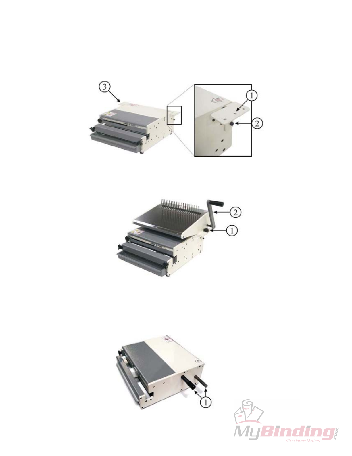
See Illustration 3.1.
Locate the two top-most and rear-most
screws on the side of your HD-
6500/7000. Inserting the short end of
the Allen wrench into the screw head,
remove the two screws.
HD-7700 Instructions;
See Illustration 3.2.
Locate the two top-most and forward-
most screws on the side of your HD-
7700. Inserting the short end of the
Allen wrench into the screw head,
remove the two screws.
Both HD-6500/7000 and HD-7700 Instructions cont...
Store the two screws removed from the punch. Locate one of the
Interface Blocks and orient it against the two now-available holes.
Orient the block so that the interface block oval hole (1) is forward
and the counter bores face out. To the right is an example of a
counter bore. Use the longer ¼”-20 socket head screws provided to secure the
Interface Block to the machine with the short end of the Allen wrench. Tighten the
rear screw first then the forward screw. Repeat this step on the other side of your
punch with the other block.
Illustration 3.1 Illustration 3.2
See illustration 3.3.
Place your HD-4470 onto your punch and secure with the 4 three winged knobs
(1) as shown. Attach the handle (2) with the brass bolt, nylock-nut, and washer
provided in the accessory kit.
Illustration 3.3

Page 5
4) Mounting the HD-4470 onto the OD-4000, OD-4012 and OD-4800;
See illustration 4.4.
Within the accessories box locate HD/OD Brackets (1) and their screws (2). The
brackets are marked left and right. Assemble them onto the sides of the punch
machine as shown (1) and (3) with the Allen wrench provided.
Illustration 4.4
See illustration 4.5.
Locate 2 three winged knobs in the accessories kit to secure the HD-4470 to
your punch. Attach the handle (2) with the brass bolt, nylock-nut, and washer
provided in the accessory kit.
Illustration 4.5
See illustration 4.6.
If you have an OD 4800 Hand Punch the new versions of the punch have
extensions (1) built in to accommodate the HD-4470 or other HD modules. If your
OD 4800 doesn’t have these extensions contact your dealer for the OD 4800
Handle Extension Kit.
Illustration 4.6

5) Determine the correct comb size.
Use the table below to determine the correct comb size for the book
thickness. You can insert more sheets into the comb, but it may affect the
appearance of your book. Covers are not included with the number of sheets
column.
Comb Diameter Book Thickness Number of sheets
Inch mm Inch mm 20lb 80gsm
3/16 4.8 1/8 3.2 30
1/4 6.4 3/16 4.8 45
5/16 7.9 1/4 6.4 65
3/8 9.5 5/16 7.9 80
7/16 11.1 3/8 9.5 95
1/2 12.7 7/16 11.1 110
9/16 14.3 1/2 12.7 125
5/8 15.9 9/16 14.3 140
3/4 19 5/8 15.9 160
7/8 22.2 3/4 19 190
1 25.4 7/8 22.2 220
1-1/8 28.6 1 25.4 250
1-1/4 31.8 1-3/32 27.8 275
1-1/2 38.1 1-3/16 30.1 300
1-3/4 44.5 1-7/16 36.5 360
2 50.8 1-11/16 42.8 425
6) Loading a Book into a Comb.
a) Placing the comb onto the rake.
Place the comb onto the rake with the fingers of the comb facing the front of
the machine. The solid section of the comb will be facing the rear of the
machine. Make sure the points of the fingers are facing up.

Page 7
b) Setting the comb opener stop.
The comb opener stop knob is located on the rear of the comb opener. Set
the comb opener stop by turning the knob counter clockwise so the combs
open far enough to place a book on the fingers of the comb, but not to far so
the comb is lying flat with no room for the book.
c) Placing the book onto the comb.
Place the holes of the book on the fingers of the comb. A slight rotating of the
book will help guide the holes onto the comb. Return the opener handle to
close the comb into the book. The binding process is now complete.
d) Die Margin setting
The margin on a standard comb die is fixed at 3/32”. This margin will work
fine until you bind books up to about 1” in comb size. After that, there is too
little paper between the edge of the hole and the edge of the sheet. Tearing of
a sheet out of the book can occur when handling the book to rough. It is
recommended when binding books beyond this size you use the optional
variable backstop comb die.
Table of contents
Popular Gate Opener manuals by other brands

Omker
Omker DCK-658 Installation manual and owner's guide

V2
V2 ATRIS-700 user manual

Beninca
Beninca DU.45E24 Operating instructions and spare parts catalogue

Beninca
Beninca BOB2124 E user manual

Chamberlain
Chamberlain TPD10-05 Mechanical and Electrical Installation Manual

LIFE home integration
LIFE home integration Armor AR024 Instructions and indications for installation, use and maintenance