Rhinestahl CTS FutureDrive NG+ User manual

USER MANUAL
WIRELESS ELECTRONIC TURNING TOOL
RC3000G01

12
FutureDriveNG™+ User’s Manual | Wireless Model RC3000G01
RHINESTAHL PROPRIETARY INFORMATION — subject to the restrictions on the cover
7687 Innovation Way, Mason OH 45040 USA | Main +1 513 229 5300 | Fax +1 513 229 3165 | rhinestahl.com
WARNING - This document may contain technical data whose export
is restricted by the Arms Export Control Act (Title 22, U.S.C. SEC 2751.
et seq.) or the Export Administration Act of 1979, as amended, Title 50,
U.S.C., App 2401 et seq. Transfer of this technical data by any means to
a Non-US Person, whether in the United States or abroad, without the
proper U.S. Government authorization (e.g., License, exemption, NLR)
is strictly prohibited.
This presentation contains information that is proprietary or
confi dential to Rhinestahl Corporation. It may not be shared with any
3rd party or reproduced without express written consent by Rhinestahl.
EXPORT STATEMENT
PROPRIETARY INFORMATION
1. MANUAL REVISION HISTORY
PAGE REVISION DESCRIPTION OF CHANGE DATE REVIEWED
BY
1. Manual Revision History
2. Abbreviations
3. Tool Description / Introduction
4. Functional Use Description
4.4 Confi gurations
5. General Safety
6. Leading Particulars
7. Installation/Removal
8. General Maintenance
9. Scheduled Maintenance
10. Calibration and Inspection Requirements
11. CE and UKCA Documentation
12. History/Rework
1
3
4
7
12
28
31
34
37
42
46
46
46
TABLE OF CONTENTS
All - Initial issue 8/27/2021 H. Mouti
M. Marasch

34
FutureDriveNG™+ User’s Manual | Wireless Model RC3000G01
RHINESTAHL PROPRIETARY INFORMATION — subject to the restrictions on the cover
7687 Innovation Way, Mason OH 45040 USA | Main +1 513 229 5300 | Fax +1 513 229 3165 | rhinestahl.com
AC Power: Alternating Current Power
PC: Personal Computer
DC: Direct Current
POS: Position
FLAG-RET: Flag Retrieval
INTV: Interval
SQ Drive: Square Drive
FOD: Foreign Object Damage
LCD: Liquid Crystal Display
VAC: Voltage Alternating Current
USB: Universal Serial Bus
XML: Extensible Markup Language
FutureDrive: FutureDriveNG+
RPM: Revolutions Per Minute
2. ABBREVIATIONS
3. TOOL DESCRIPTION / INTRODUCTION

56
FutureDriveNG™+ User’s Manual | Wireless Model RC3000G01
RHINESTAHL PROPRIETARY INFORMATION — subject to the restrictions on the cover
7687 Innovation Way, Mason OH 45040 USA | Main +1 513 229 5300 | Fax +1 513 229 3165 | rhinestahl.com
Rhinestahl’s FutureDriveNG™ is a precision electronic tool used to automate
the process of rotating a gas turbine engine for multiple applications. There are
three main components, the Power Unit, Drive Motor and Hand Control, with
additional cables to connect components, power, and other accessories as
needed or required. Refer to Figure 1 for all included items.
FutureDriveNG™+
Figure 1: FutureDriveNG+ Kit
QTY IDENTIFICATION CAGE CODE ITEM
ZONE
ITEM
NO. DESCRIPTION OR NAME
1 RC3001G01 2 POWER UNIT ASSEMBLY W/ VIDEO
OVERLAY & WIRELESS CAPABLE
1 RC3002G01 3 HAND CONTROL ASSEMBLY, WIRELESS
CAPABLE
1 RC3003G01 4 MOTOR ASSEMBLY
1 RC2010P104 5 CABLE ASSEMBLY, HAND CONTROL
1 RC2010P105 6 CABLE ASSEMBLY, MOTOR
1 RC3004G01 7 SWITCH, FOOT, REMOTE, WIRED
1 RC3005G01 8 SWITCH, HAND, REMOTE, WIRED
1 RC3006G01 9 CASE, CARRYING, WHEELED, LARGE
1RC3000G01 -
MANUAL 10 MANUAL, OPERATIOR
5 RC2000P53 11 SHEAR PIN
1 RC2140P01 12 POWER CORD, U.S. STD - 90” LG
1 RC2170P01 4U744 13 CABLE ASSY, COAX - AUXILARY SWITCH
1AK-AV200 14 CABLE RCA MALE-MALE 1.5M
1AK672/2-3-
BLACK 15 CABLE USB 2.0 MALE

78
FutureDriveNG™+ User’s Manual | Wireless Model RC3000G01
RHINESTAHL PROPRIETARY INFORMATION — subject to the restrictions on the cover
7687 Innovation Way, Mason OH 45040 USA | Main +1 513 229 5300 | Fax +1 513 229 3165 | rhinestahl.com
4. FUNCTIONAL USE DESCRIPTION
The power unit (Figure 2)is the central hub of the FutureDrive system.
In addition to the AC power connectors for the hand control and drive motor,
the power unit also offers the following connectors:
1. Composite video IN/OUT and S-Video IN/OUT: the power unit can
overlay information about the engine, stage and blade onto the signal
from a video borescope. Plug the video output from the borescope
into one of the power unit’s composite video or S-video IN jacks and
connect a cable from the power unit’s composite video or S-video
OUT jack to a monitor or video recorder.
2. USB: To install software updates or upgrades to a Future- Drive,
Rhinestahl will provide a PC software package that will upgrade
the unit via a USB cable. This can be used to add new features or
additional engine models. The hand control must be connected to the
power unit via its own cable when the update is in progress.
3. Use the USB port to connect the turning tool system with a
communication capable borescope. An XML output on the serial port
for Engine/Stage/Blade/Flag information shall appear on the device.
1. For the borescope system:
• Send command ‘e1’ to enable the output from the turning
tool system to the borescope
• Send command ‘e0’ to turn off the output from the turning
tool system to the borescope
2. The live output is as follows:
• Stage number data
• Blade number data
4.1 POWER UNIT

910
FutureDriveNG™+ User’s Manual | Wireless Model RC3000G01
RHINESTAHL PROPRIETARY INFORMATION — subject to the restrictions on the cover
7687 Innovation Way, Mason OH 45040 USA | Main +1 513 229 5300 | Fax +1 513 229 3165 | rhinestahl.com
Figure 2: Power Unit Face
DC brushless servo motor design with a machined, aircraft-aluminum housing
and high-resolution encoder feedback for full motion control range with
digital accuracy. High torque gearbox ensures reliable operation. Variable
acceleration design provides for minimal backlash problems during operation.
Equipped with two alignment dowel pins and (x4) ¼-20 captive screws for
convenience and ease of installation. The motor (Figure 3) is equipped with a
shear pin as a failsafe to protect the motor from overload and ensure delivered
torque does not exceed the allowable limits.
• Motor Weight 5.0 lbs (2.27 kg)
• Dimensions 3.25” x 2.5” x 10” (8.26 x 6.35 x 25.4 cm)
• Motor Torque Limit 110 ft. lbs. (149.14 Nm)
• Shear Pin Braking Force 90 ft. lbs. (122.02 Nm)
• Drive ½” sq. Drive
The hand control is ergonomically designed to fi t in the palm of the hand. It
incorporates simple, user-friendly control buttons to allow for quick set up and
operation.
The barbell-shaped engine rotation indicator will spin whenever the turning
tool motor is turning (Figure 4, Item 2).
After a period of inactivity, the hand control may blank its screen and go to
sleep to conserve power. Simply press the round button to wake it up again
(Figure 4, Item 1).
4.2 DRIVE MOTOR
NOTE
4.3 HAND CONTROL
Note: Any time the engine is moving, pressing this button will act as an emergency stop.
Figure 4: Drive Motor

11 12
FutureDriveNG™+ User’s Manual | Wireless Model RC3000G01
RHINESTAHL PROPRIETARY INFORMATION — subject to the restrictions on the cover
7687 Innovation Way, Mason OH 45040 USA | Main +1 513 229 5300 | Fax +1 513 229 3165 | rhinestahl.com
The battery indicator shows the battery charge. If the cable is plugged in, the
icon will animate to show that the battery is charging. The hand control should
be plugged to the power unit once the battery indicator shows two bars or less
(Figure 4, Item 3).
Current blade — the large number always shows which blade is currently visible
in the borescope (Figure 4, Item 4).
Either the hand or foot switch can be connected to this jack if desired for Jog,
Blade to Blade, or continuous turn operation (Figure 4, Item 5).
4.3 HAND CONTROL
4.4 CONFIGURATIONS
Figure 3: Hand Control
3
1
2
4
5

13 14
FutureDriveNG™+ User’s Manual | Wireless Model RC3000G01
RHINESTAHL PROPRIETARY INFORMATION — subject to the restrictions on the cover
7687 Innovation Way, Mason OH 45040 USA | Main +1 513 229 5300 | Fax +1 513 229 3165 | rhinestahl.com
This mode shows the model number and serial number of the unit, plus
information about the installed software. This is also where the screen
brightness and contrast can be adjusted.
The unit will always remember the brightness and contrast settings from
the previous use. If the unit was previously used in very different lighting
conditions, the screen may be hard to read until the settings are changed.
SET UP MODE
Figure 5: Set Up Mode
How to select engine type:
When the FutureDrive is powered on, the hand control will display the startup
screen for a few seconds, then will automatically go to the ENGINE screen.
ENGINE
Figure 6: Engine Screen
Use the keys to cycle
through the available engine
choices. Additional engine
data may be ordered from
Rhinestahl Corporation.
Press to go to
the next step
Use the keys to cycle
Press to go to

15 16
FutureDriveNG™+ User’s Manual | Wireless Model RC3000G01
RHINESTAHL PROPRIETARY INFORMATION — subject to the restrictions on the cover
7687 Innovation Way, Mason OH 45040 USA | Main +1 513 229 5300 | Fax +1 513 229 3165 | rhinestahl.com
How to compensate for gearbox looseness:
The engine gearbox will have a certain amount of backlash — backlash is
looseness between gear teeth in a gear train. Because of backlash, the
engine will not move until the slack in the gears is taken up. This step tells the
FutureDrive how much backlash is present, so it can compensate and make
precise movements.
Note: If the selected engine is not bi-directional, the FutureDrive will skip this step.
BACKLASH
Figure 7: Backlash Screen
Step 1 Step 2 Step 4
Step 3
Step 8
Step 7
Step 5 Step 6
NOTE
BACKLASH
How to setup backlash:
1. Press ENGINE button.
2. Press middle to highlight speed on LCD screen.
3. Use buttons to lower speed to 0.10 RPM for precision setting.
4. Press far left to highlight backlash on LCD screen.
5. Press and hold until fi rst sign of blade movement on Borescope
screen.
i. During this step press and hold the corresponding directional
arrow button continuously or intermittently as needed.
ii. Backlash compensation and directional arrow is displayed
on the hand control screen as a numerical value even if
physical movement is not visible on the borescope screen.
6. Press and hold until fi rst sign of blade movement on
Borescope screen.
i. During this step press and hold the corresponding directional
arrow button continuously or intermittently as needed.
ii. Backlash compensation and directional arrow is displayed
on the hand control screen as a numerical value even if
physical movement is not visible on the borescope screen.
7. Press if satisfi ed with backlash setting. Otherwise, repeat steps 5
and 6 until backlash amount is captured then press button.
8. Use buttons to reset inspection RPM to preferred setting.
Press middle to highlight speed on LCD screen.
Press far left to highlight backlash on LCD screen.
Use buttons to lower speed to 0.10 RPM for precision setting.
8. Use buttons to reset inspection RPM to preferred setting.
Press and hold until fi rst sign of blade movement on Borescope
Use buttons to lower speed to 0.10 RPM for precision setting.
8. Use buttons to reset inspection RPM to preferred setting.
7. Press if satisfi ed with backlash setting. Otherwise, repeat steps 5
and 6 until backlash amount is captured then press button.
6. Press and hold until fi rst sign of blade movement on

17 18
FutureDriveNG™+ User’s Manual | Wireless Model RC3000G01
RHINESTAHL PROPRIETARY INFORMATION — subject to the restrictions on the cover
7687 Innovation Way, Mason OH 45040 USA | Main +1 513 229 5300 | Fax +1 513 229 3165 | rhinestahl.com
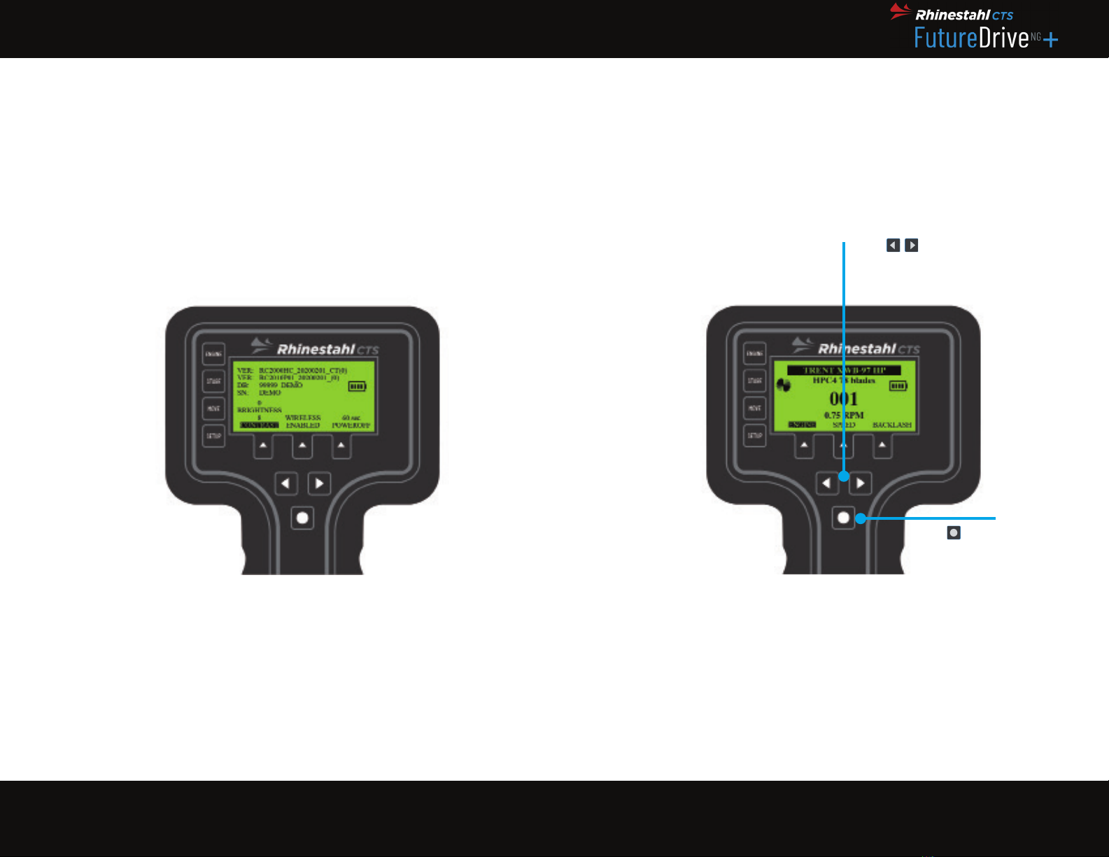
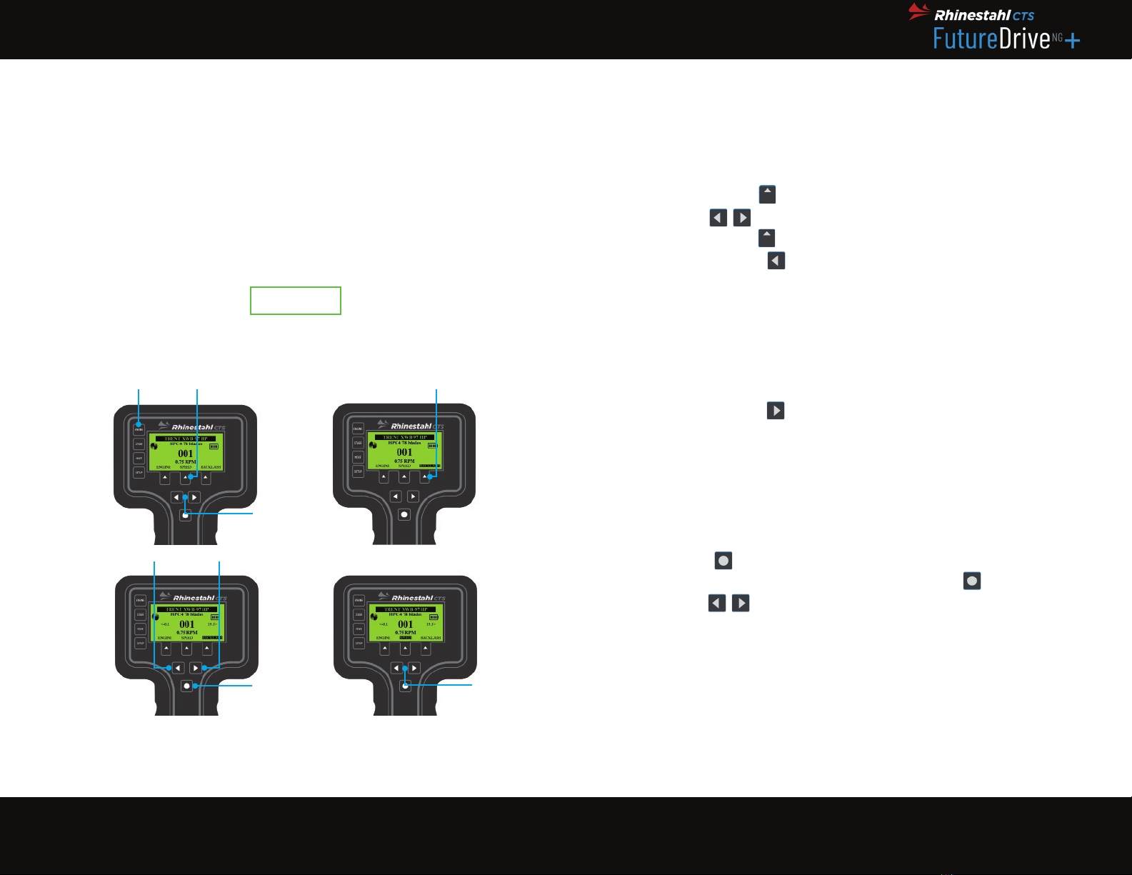
How to select the engine stage to inspect:
The FutureDrive will come pre-programmed for the applicable engine. The unit
knows all the engine’s stages, blade counts, the torque required to turn the
engine, and other information. When the unit is powered on, it will remember
the selected stage from the previous time the unit was used.
STAGE
Note: If backlash is set, changing rotational direction during all move modes will trigger a fl ashing
backlash message. The message with appear on the screen while system compensates for looseness
in the gearbox and will disappear once this action is complete. During backlash compensation time
interval, all hand control buttons will be disabled until this operation is complete, then hand control
button functionality is automatically restored.
Indicates the currently
selected stage and the
number of blades in that stage
Anytime you need
to return to this
screen and change
stages, press the
STAGE button
Use to
cycle through
engine’s stages
Use to
Use to
Figure 8: Stage Screen
NOTE
How to move the blade in the borescope view:
The jog function allows for positioning of the blades per user preference in how
they’re viewed via borescope. SET VIEW POS will lock this position in, and the
FutureDrive will always stop at this same position for each blade viewed in this
stage. Use JOG and SET VIEW POS for each stage.
When using SET VIEW POS, the current blade will become blade 1 for this
stage.
JOG
Note: If backlash is set, changing rotational direction during all move modes will trigger a fl ashing
backlash message. The message with appear on the screen while system compensates for looseness
in the gearbox and will disappear once this action is complete. During backlash compensation time
interval, all hand control buttons will be disabled until this operation is complete, then hand control
button functionality is automatically restored.
Figure 9: Jog Screen
Use to move the
current blade until it is
positioned the way you
want to view it in the
borescope. Jog can also
be used anytime you want
to turn the engine by an
arbitrary amount, rather
than blade-by-blade.
When you are happy with the view
in the borescope, press under
SET VIEW POS to lock it in. This
FutureDrive will now stop at this
view position on all other blades.
Press and release to
cycle through the various
modes: Jog, Blade, Interval,
and Flag Blade Retrieval
Anytime you need to
return to this screen,
use the MOVE button
Use to move the
When you are happy with the view
in the borescope, press under
Press and release to
NOTE

19 20
FutureDriveNG™+ User’s Manual | Wireless Model RC3000G01
RHINESTAHL PROPRIETARY INFORMATION — subject to the restrictions on the cover
7687 Innovation Way, Mason OH 45040 USA | Main +1 513 229 5300 | Fax +1 513 229 3165 | rhinestahl.com
How to set blade-by-blade movement:
This allows user to move one blade per push of the keys. Each blade
will always stop at the position selected with SET VIEW POS. If the hand or foot
switch is connected, it can be used instead of the keys.
• An entire engine inspection can be completed with this method. Use the
STAGE button to change to the next stage, then use JOG and SET VIEW
POS again.
• For more accessibility, connect the auxiliary hand or foot switch for
forward rotation only (Figure 11)
Note: If backlash is set, changing rotational direction during all move modes will trigger a fl ashing
backlash message. The message with appear on the screen while system compensates for looseness
in the gearbox and will disappear once this action is complete. During backlash compensation time
interval, all hand control buttons will be disabled until this operation is complete, then hand control
button functionality is automatically restored.
BLADE
Figure 10: Blade Screen
This allows user to move one blade per push of the keys. Each blade
NOTE
Press and release to
cycle through the various
modes: Jog, Blade, Interval,
and Flag Blade Retrieval
Anytime you need to
return to this screen, use
the MOVE button
This large number always
shows the blade in view
through the borescope
Press either of the
keys three times quickly
and the GOTO indicator
will appear. This shows
the fi nal blade number the
FutureDrive will stop on.
Keep rapidly clicking until
you see the blade number
you want to move to.
Use the keys to move
either forwards or backwards
through the blades. The
FutureDrive will advance by
one blade for every press of the
buttons.
Press either of the
Use the keys to move
Press either of the
Use the keys to move
Press and release to
Note: If backlash is set, changing rotational direction during all move modes will trigger a fl ashing
backlash message. The message with appear on the screen while system compensates for looseness
in the gearbox and will disappear once this action is complete. During backlash compensation time
interval, all hand control buttons will be disabled until this operation is complete, then hand control
button functionality is automatically restored.
The FutureDrive tool allows the operator to move to a particular blade at any
time. This is done as follows:
1. Use MOVE button to select BLADE.
2. Press rapidly to bring up the GOTO indicator – keep pressing
until the desired blade number is displayed, and the Drive
Motor will go to that blade. Bi-directional engines can be turned
in either direction – using to move or GOTO either way.
GO TO BLADE
Figure 11: Auxiliary Hand Switch to Control Blade Screen
in either direction – using to move or
Press rapidly to bring up the
until the desired blade number is displayed, and the Drive
in either direction – using to move or
NOTE

21 22
FutureDriveNG™+ User’s Manual | Wireless Model RC3000G01
RHINESTAHL PROPRIETARY INFORMATION — subject to the restrictions on the cover
7687 Innovation Way, Mason OH 45040 USA | Main +1 513 229 5300 | Fax +1 513 229 3165 | rhinestahl.com
FLAG
How to fl ag a blade:
A fl ag is a bookmark that allows for easy return to a particular blade, such as
one that is damaged or questionable. Even if an inspection of other stages of
the same engine continues, the FutureDrive remembers all fl agged blades for
each stage.
Note: Flagged blades can only be removed in fl ag-retrieval mode.
Press under
FLAG to set a fl ag for
the current blade
The FLAG indicator
shows that the current
blade is fl agged
Press and release to
cycle through the various
modes: Jog, Blade, Interval,
and Flag Blade Retrieval
Anytime you need to
return to this screen,
use the MOVE button
Press and release to
Press under
Figure 12: Flag Screen
NOTE
The motor drive can mark questionable blades for re-inspection. This is done
as follows:
1. Press FLAG
2. The word FLAG will appear on the right side of the screen for fl agged
blades. It will be blank for un-fl agged blades.
At any point during the inspection of a stage, the operator can move any
fl agged blades by performing the following procedure:
1. Select the stage that the fl ag blade is on with STAGE. Then go to
MOVE and select FLAG-RET.
2. Press to move to the next highest blade that has been fl agged (if
there are no blades fl agged in the current stage, the unit will not turn
at all). Quickly pressing steps through the fl agged blades and the
Drive Motor will stop at the last one selected.
3. Press to move to the previous blade that has been fl agged.
Note: Blades can be fl agged while in interval movement mode by pressing FLAG.
BLADE FLAG
Blades can be fl agged while in interval movement mode by pressing
Press to move to the previous blade that has been fl agged.
Press to move to the next highest blade that has been fl agged (if
at all). Quickly pressing steps through the fl agged blades and the
Press
NOTE

23 24
FutureDriveNG™+ User’s Manual | Wireless Model RC3000G01
RHINESTAHL PROPRIETARY INFORMATION — subject to the restrictions on the cover
7687 Innovation Way, Mason OH 45040 USA | Main +1 513 229 5300 | Fax +1 513 229 3165 | rhinestahl.com
FLAG RETRIEVAL
How to return to a fl agged blade:
Find and return to the blades fl agged earlier in the inspection process. The
FutureDrive will remember every blade fl agged in every stage of the engine.
New blades cannot be fl agged in FLAG-RET mode; the only functionality is
fi nding and returning to fl agged blades, and unfl agging them (Figure 14). Select
BLADE to fl ag a new blade.
Figure 13: Flag Retrieval Screen
Press and release until
FLAG-RET is selected
GOTO indicates the
selected fl agged blade
that the FutureDrive is
moving to
Use the keys
to move to the next or
previous fl agged blade. The
GOTO indicator will show
the fl agged blade’s number
and the FutureDrive will
begin to move to that blade.
Anytime you need to return
to this screen, use the
MOVE button
Press and release until
Use the keys
Use the keys
Use the keys
Figure 14: Unfl agging Blade Screen
If you decide to un-fl ag
the blade, press . The
FutureDrive will toggle
the fl ag on or off for this
blade. You can fl ag blades
in other modules, but you
can only un-fl ag them using
FLAG-RET.
Anytime you need to return
to this screen, use the
MOVE button
When you arrive to the fi rst
fl agged blade, the GOTO
indicator vanishes and the
FLAG indicator appears
Press the button to
interrupt the Go-To process
If you decide to un-fl ag
the blade, press . The
Press the button to
How to set interval speed:
This mode automatically moves the engine, starting at the current blade
through the last blade on the stage. It can be set for continuous travel (INTV:0)
or can pause at each blade if INTV is set to 1 (for 1 second) or above (up to 99
seconds). This allows the user to work entirely hands-free. If a video recorder is
used, the inspection can be recorded unattended.
INTERVAL
Note: If backlash is set, changing rotational direction during all move modes will trigger a fl ashing
backlash message. The message with appear on the screen while system compensates for looseness
in the gearbox and will disappear once this action is complete. During backlash compensation time
interval, all hand control buttons will be disabled until this operation is complete, then hand control
button functionality is automatically restored.
Figure 15: Interval Screen
Use to set the
interval (the delay between
each automatic blade move).
This determines how long
the FutureDrive will pause at
each blade. “0” is continuous,
“1” is one second, etc.
The word INTV will fl ash whenever
interval moment is in progress. The
number after INTV indicates the
pause at each blade as the engine is
turned automatically
Blades can be
fl agged using ,
or the hand or
foot switch if
connected
Use to set the
Use to set the
Press and release
until INTV is
selected
Anytime you need to
return to this screen,
use the MOVE button
When you are ready to start,
press to begin interval
movement. Press again
to pause or stop.
When you are ready to start,
press to begin interval
movement. Press again
fl agged using ,
NOTE
until

25 26
FutureDriveNG™+ User’s Manual | Wireless Model RC3000G01
RHINESTAHL PROPRIETARY INFORMATION — subject to the restrictions on the cover
7687 Innovation Way, Mason OH 45040 USA | Main +1 513 229 5300 | Fax +1 513 229 3165 | rhinestahl.com
CONTINUOUS
How to set continuous mode:
This mode automatically moves the engine core a set number of full rotations
starting at the current blade through the last blade.
Set up steps:
1. Press MOVE button to cycle through move modes and select
continuous.
2. Press to set the number of engine core full rotations.
3. Press and quickly release button for clockwise rotation.
4. Press and hold button for two to fi ve seconds for
counterclockwise rotation.
Note: during continuous operation, press button to interrupt continuous rotation progress.
Press and quickly release button for clockwise rotation.
Press and hold button for two to fi ve seconds for
Press to set the number of engine core full rotations.
Note: during continuous operation, press button to interrupt continuous rotation progress.
Note: If backlash is set, changing rotational direction during all move modes will trigger a fl ashing
backlash message. The message with appear on the screen while system compensates for looseness
in the gearbox and will disappear once this action is complete. During backlash compensation time
interval, all hand control buttons will be disabled until this operation is complete, then hand control
button functionality is automatically restored.
Figure 16: Continuous Screen
NOTE
NOTE
How to set speed:
The SPEED setting determines how quickly the engine rotates when it is
moving between blades. The values are in RPM (revolutions per minute). The
speed can be changed at any time.
Note: Speed can be changed at any time, even during a movement.
The FutureDrive system allows a wide range of engine turning speeds to be
used. The speed is selected as follows:
1. Press MOVE; select SPEED.
2. Use to select the speed desired. The possible range of speeds
is in .01 – 2 RPM (the unit compensates for gearbox ratios so the
engine core will turn at this speed).
3. Select SPEED again to exit the Speed Setting Mode.
SPEED
; select
Select
Use to select the speed desired. The possible range of speeds
Figure 17: Speed Screen
Use to change the
speed value. Whatever speed
appears here will be used for
all engine movements.
Press to select speed
Use to change the
Use to change the
Press to select speed
Anytime you need to
return to this screen,
use the MOVE button
NOTE

27 28
FutureDriveNG™+ User’s Manual | Wireless Model RC3000G01
RHINESTAHL PROPRIETARY INFORMATION — subject to the restrictions on the cover
7687 Innovation Way, Mason OH 45040 USA | Main +1 513 229 5300 | Fax +1 513 229 3165 | rhinestahl.com
SPEED
The auxiliary hand and foot switch (Figure 18)are equivalent to the key. This
allows movement of the engine from blade to blade without using the hand
control.
In INTERVAL Mode, the hand and foot switches can be used to FLAG blades.
Click and release to set the FLAG – do not hold the switch down.
are equivalent to the key. This
Figure 18: Auxilary Hand and Foot Switch
5. GENERAL SAFETY

29 30
FutureDriveNG™+ User’s Manual | Wireless Model RC3000G01
RHINESTAHL PROPRIETARY INFORMATION — subject to the restrictions on the cover
7687 Innovation Way, Mason OH 45040 USA | Main +1 513 229 5300 | Fax +1 513 229 3165 | rhinestahl.com
Warning statements: A warning statement is a description of a situation
where a potentially hazardous condition exists that could result in the death or
serious injury of workers and/or the general public if not avoided.
Caution statements: A caution statement is a description of situations where a
non-immediate or potential hazard presents a lesser threat of injury that could
result in minor or moderate injuries to workers and/or the general public.
Note statements: A note statement is used to notify people of installation,
operation, programming, or maintenance information that is important, but not
hazard-related.
• The tool must be visually inspected for damage and all major components
must be present before every use.
• Check all moving components and mechanisms to be fully operational.
• This tool is expected to be used by a qualifi ed trained operator(s).
• Shock loading of tools is prohibited.
• Fixtures should be used in a well-lit, clean, non-explosive environment.
• Tools should not be forced into or be used in a purpose contrary to its
intended use.
• All personnel are required to use Personal Protective Equipment as
approved by the Facility.
• Do not overreach when using the tool.
• Stay Alert: watch what you are doing and use common sense.
• Report any defects to the appropriate supervisor
5. GENERAL SAFETY
WARNING
!
NOTE
CAUTION
Warning: Use caution with the FutureDrive unit to avoid electric shock. Do not
use the unit if cables are damaged or if the unit has been exposed to moisture.
High voltages can lead to injury or death.
Warning: The cord set or the ON/OFF switch can be used as a disconnect
device
Warning: Do not replace electrical supply cords with inadequately rated cords.
5. GENERAL SAFETY
WARNING
!
WARNING
!
WARNING
!

31 32
FutureDriveNG™+ User’s Manual | Wireless Model RC3000G01
RHINESTAHL PROPRIETARY INFORMATION — subject to the restrictions on the cover
7687 Innovation Way, Mason OH 45040 USA | Main +1 513 229 5300 | Fax +1 513 229 3165 | rhinestahl.com
6. LEADING PARTICULARS
• Power Unit 6.75” x 2” x 9” (17.15 x 5.08 x 22.86 cm)
• Motor Drive 3.25” x 2.5” x 10” (8.26 x 6.25 x 25.40 cm)
• Hand Controller 2” x 5” x 8.75” (5.08 x 12.70 x 22.23 cm)
• Aux. Hand Switch 0.75” diameter x 5” (1.91 cm diam. x 12.70 cm)
• Aux. Foot Switch 2” x 3.5” x 5.5” (5.08 x 8.89 x 13.97 cm)
• Entire Package 39.2 lbs. (17.8 Kg), including case,
cables and all accessories.
• Main Power Unit 4 lbs. (1.85 Kg)
• Motor Drive Hand 5 lbs. (2.27 Kg)
• Controller 1 lbs. (.45 Kg)
• Voltage 110 - 240 VAC, 2A
• Hertz 47 – 63
• Fuse 5mm x 20mm Glass Tube Fast-Acting, 250 VAC, 2A
• Voltage Fluctuations +/- 10%
Ensure that provided power cable is plugged into a proper receptacle EARTH
GROUND feed.
• Operating Temp. -10 C to 40 C (14 F to 104 F)
• Storage Temp. -10 C to 70 C (14 F to 158 F)
• Humidity 0 to 96%
• Altitude 1,500m
• Pollution Degree 2
• Ip Rating IP 30
6.1 PHYSICAL SIZE
6.2 WEIGHT
6.3 ELECTRICAL REQUIREMENTS
WARNING
!
6.4 ENVIRONMENTAL

33 34
FutureDriveNG™+ User’s Manual | Wireless Model RC3000G01
RHINESTAHL PROPRIETARY INFORMATION — subject to the restrictions on the cover
7687 Innovation Way, Mason OH 45040 USA | Main +1 513 229 5300 | Fax +1 513 229 3165 | rhinestahl.com
• Speed Variable from .01 to 2 RPM of the engine core
• Direction Bi-directional
• Torque Motor Drive rated at 120 ft.lb (162.70 Nm);
shear pin rated to 90 ft.lb (122.02 Nm)
• Interval Timer 0 to 99 seconds between blades
• Blade Counter Up to 999
• Blade Flagging Damaged blade locations can be fl agged and
automatically repositioned
• Control Type Simple multiplexing one hand control design with
emphasis on simple operation without sacrifi cing
full functional versatility. Backlit LCD display
provides for maximum visibility in widest variety of
operating.
• Battery Power NiMH 9.6 V
• Electronics Microprocessor based system design ensures
reliable operation
• Drive Motor DC brushless servo motor design with a machined,
aircraft-aluminum housing, and high-resolution
encoder feedback for full motion control range
with digital accuracy. High torque gearbox ensures
reliable operation. Variable acceleration design
provides for minimal backlash problems
during operation.
6.5 OPERATION
7. INSTALLATION/REMOVAL

35 36
FutureDriveNG™+ User’s Manual | Wireless Model RC3000G01
RHINESTAHL PROPRIETARY INFORMATION — subject to the restrictions on the cover
7687 Innovation Way, Mason OH 45040 USA | Main +1 513 229 5300 | Fax +1 513 229 3165 | rhinestahl.com
Attach the drive motor to the engine (some engine models may require an
adapter).
Connect the drive motor to the power unit via the supplied drive cable. Be sure
to completely tighten the connectors.
The wireless model can be used with or without the cable. The battery will
recharge if the cable is used. See Figure 19 for the correct method to connect/
disconnect the hand control cable. Attach the Hand Control Cable by aligning
the connectors and then twisting the collar to lock it in place. Remove the
connector by fi rst untwisting the collar.
• If the auxiliary hand switch or auxiliary foot switch is to be used, connect
it to the hand control with the supplied auxiliary switch cable. This cable is
connected by aligning the pin to the slot, pushing the connectors together
and then giving the connector a slight clockwise turn.
• Connect the Power Unit to the appropriate power source via the supplied
power cord. Only use a grounded outlet.
7. INSTALLATION/REMOVAL
Figure 19: Connect/Disconnect Hand Control Cable
NOTE
Note: It is recommended to always connect the hand control to the power unit via hand control during
set up.
• Turn on the FutureDrive system via the switch on the Power Unit. The Hand
Control will wake up and its display will light.
Warning: It is very important for the proper operation to make sure all cables are securely connected
before turning on the power. If the unit seems to be behaving improperly, turn the power off, check all
connections, and turn the power back on. Do not use power source outside of electrical requirement
(see Section 6).
Follow above steps in reverse order for removal.
7. INSTALLATION/REMOVAL
WARNING
!
Once set up, the FutureDrive is used to perform the standard borescope
inspection procedure as follows (refer to Section 4.4 for detailed set up
instructions):
1. Set backlash
2. Select the stage to inspect
3. Jog the engine to zero the blade under the borescope at the desired
blade viewing point
4. The unit can now bring each blade in the stage into view
5. At this time, move through each stage of the inspection by performing
steps 2-4 in succession for each stage.
7.1 NORMAL OPERATIONS

37 38
FutureDriveNG™+ User’s Manual | Wireless Model RC3000G01
RHINESTAHL PROPRIETARY INFORMATION — subject to the restrictions on the cover
7687 Innovation Way, Mason OH 45040 USA | Main +1 513 229 5300 | Fax +1 513 229 3165 | rhinestahl.com
8. GENERAL MAINTENANCE
Clean the unit thoroughly using only a dry, soft, clean cotton cloth. Never use
any solvents or cleaning solutions – these can damage the Hand Control’s
display.
This unit is designed for indoor and outdoor use. The user must ensure the unit
does not get wet or damp due to the nature of electronics and other sensitive
components. Refer to the environmental specifi cations in Section 6.4 for
temperature/humidity range of operation.
Only use original FutureDrive components and adapters with this tool. Use
of non-original FutureDrive parts can lead to failure of unit and voiding of
warranty.
Periodically check all cables and connectors for wear and damage and clean
the contacts if necessary.
Replacement fuse: 5mm x 20mm Glass-Tube Fuse Fast Acting, 250 VAC, 2 Amp
• Store tool in supplied storage case.
• Apply a light coat of corrosion preventative oil on all non-painted surfaces
when stored.
8. GENERAL MAINTENANCE
8.1 STORAGE
Other manuals for FutureDrive NG+
1
This manual suits for next models
1
Table of contents
Other Rhinestahl CTS Tools manuals