RHINO RMCS-3002 User manual

Rhino Industrial Brushless DC Motor Drive
with UART ASCII Compatible
(Model No : RMCS –3002)
Operating Manual v1.0

Page | 2
Contents
Introduction –Salient Features ....................................................................................................................3
Technical specifications and Pin description ................................................................................................ 4
Description of the four modes of Operation and Slave ID settings ..............................................................5
How to use the drive:....................................................................................................................................7
Steps to configure the Drive using Modbus Poll Software: ..........................................................................7
STEP 1: Hardware Connection ..................................................................................................................8
STEP 2: Connect Modbus UART ASCII Drive with Modbus Poll Software...............................................10
Step 3: Set slave ID in Modbus Poll Software to send and receive Data ................................................12
Step 4: Go to Function ............................................................................................................................15
STEP 5: Program the drive to run in any one of the four modes:..........................................................17
Mode 0 –Analog input controlled Open Loop PWM mode: ..............................................................17
Mode 1 –Modbus UART ASCII Controlled Closed Loop Speed Mode:...............................................20
Mode 2 –Digitally Controlled Open Loop PWM Mode: .....................................................................24
Mode 3- Analog Input Closed Loop Mode .......................................................................................... 27
STEP 6: Save and Reset settings in Drive ................................................................................................29
Appendix: ....................................................................................................................................................30
1. Registers.................................................................................................................................................. 30
2. BLDC Motors ........................................................................................................................................... 30
Troubleshooting:......................................................................................................................................... 31

Page | 3
Introduction –Salient Features
Rhino Motion Controls RMCS-3002 with UART ASCII is a high performance brushless dc drive (10–30 V DC)
designed for optimized operation of Rhino brushless DC motors with Hall sensor feedback. This is an amazing cost
effective solution to provide closed loop/open loop control for various applications. The salient features of this drive:
•This drive provides a closed loop/open loop speed control for the brushless dc system.
•The motor programmed speeds are maintained irrespective of the voltages supplied.
•Also by using this drive, the rated torque of the motor is available at all speeds and the torque does not
decrease with change in speeds.
•It is possible to run the motor in four different modes.
•It has short-circuit protection for the motor outputs, over-voltage and under-voltage protection and will
survive accidental motor disconnects while powered-up.
•This drive is configured using MODBUS ASCII protocol via UART.
•There is a function in the drive for setting the Modbus Slave Address from 1 to 7 using physical jumpers
(Hardware Setting) or using MODBUS Tool Device (Software Setting).
•There are four user modes in the drive :
•Mode 0: Analog input controlled Open Loop PWM mode
•Mode 1: Modbus UART ASCII Controlled Closed Loop Speed Mode
•Mode 2: Digitally Controlled Open Loop PWM Mode
•Mode 3: Analog Input Closed Loop Mode

Page | 4
Technical specifications and Pin description
Supply Voltage and Current
Specification
Min
Max
Units
Comments
Supply Voltage
10
30
Volts DC
Between +Ve and GND
Phase Current
0.5
3
Amps
Peak 5 Amps per phase
Pin description of the drive is as per below image:
(Pins 1-7 are used for drive
Configuration and UART control)
Pin No.
Description
8
GND
9
+5VDC
10
ENC_B/Hall W
11
ENC_A/Hall U
12
Hall U
13
W
14
Motor- / V
15
Motor+ / U
16
VDD
17
GND
Pin No.
Description
1
GND
2
RXD
3
TXD
4
ENA
5
ADC
6
DIR
7
BRK
Pin No.
Description
JP1
Jumper 1
JP2
Jumper 2
JP3
Jumper 3
(Pins 8 - 17 are connected to
motor and power supply as
described)
(Jp1 to JP3 are used for
Hardware setting of slave ID)

Page | 5
Description of the four modes of Operation and Slave ID settings
Before we describe the configuration settings and connection diagram of the drive with the motor, we would like to
describe the four modes in which the BLDC motor can run and slave ID addressing which are unique features of the
drive.
Different Modes of Operation: The drive can be configured in the following four modes by the user –
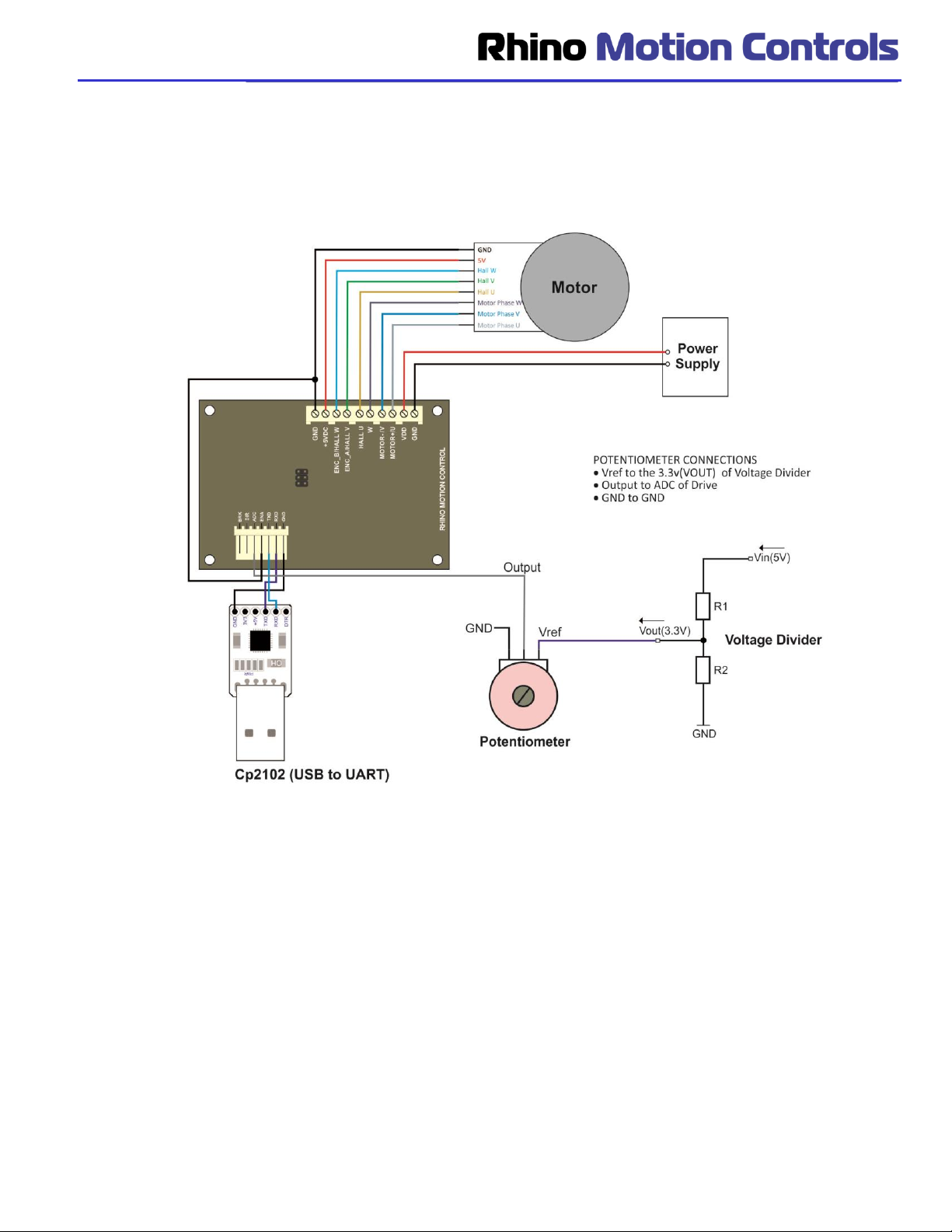
Note: Modes 0 and 3 are Analog Input modes in which a 3.3 V driven potentiometer has to be interfaced with the
‘ADC’ pin of the drive externally
1. Mode 0 Analog input controlled Open Loop PWM mode:
a. In this mode the speed of the Rhino BLDC motor can be controlled by an externally connected
Potentiometer.
b. User can increase or decrease the speed manually based on requirement.
c. The drive will provide full torque at all speeds within the range.
d. However the potentiometer has to be connected via a voltage divider to provide a maximum of 3.3
volts so as to not damage the drive.
e. Also the Enable, Brake has to be connected as per configuration requirements.
f. Direction can not be changed in this mode.
2. Mode 1 Modbus UART ASCII Digitally Controlled Closed Loop Speed Mode:
a. In this mode the frequency and direction of the Rhino BLDC motor is settable / controllable via a
Computer / Arduino Controller board / any other Modbus ASCII compatible device.
b. This mode is used when multiple motors are to be used to run at exactly the same Frequency.
3. Mode 2 Digitally Controlled Open Loop PWM Mode:
a. This mode is used when multiple motors are to be used to run at exactly the same or different
PWM as per the applications.
b. In this mode the direction of the motor can be controlled digitally via Modbus ASCII commands to
run the BLDC motor in both directions
4. Mode 3: Analog Input Closed Loop Mode:
a. In this mode the speed of the Rhino BLDC motor can be controlled by an externally connected
Potentiometer.
b. User can set the minimum speed of the motor and increase or decrease the speed manually
based on requirement.
c. The drive will provide full torque at all speeds within the range.
d. However the potentiometer has to be connected via a voltage divider to provide a maximum of 3.3
volts so as to not damage the drive.
e. Also the Enable, Brake has to be connected as per configuration requirements.
f. Direction cannot be changed in this mode.

Page | 6
Slave ID Addressing: The second unique feature in this drive is that a single controller can be used to control seven
drives at the same time using the physical jumpers. Using the Modbus Poll software, the slave ID can be set from 1 to
247. However, in this driver, we can set slave ID from 1 to 7 using physical jumpers also. As shown in the image
below there are three jumpers marked by a red circle shown in the image below.
The three jumpers JP1, JP2 and JP3 can be set in the configuration as per the below table to provide a physical
slave address to the drive. In the below table a value of ‘0’ corresponds to a state where the jumper is not connected
and a value of ‘1’ corresponds to a state where the jumper is connected. If none of the jumpers are connected the
drive has been programmed to use the Slave ID 1 in default mode.
Slave ID
JP1
JP2
JP3
Image of
connection on the
Drive
1
0
0
1
2
0
1
0
3
0
1
1
4
1
0
0
5
1
0
1
6
1
1
0
7
1
1
1

Page | 7
How to use the drive:
The drive needs to be configured to run in any one of the four modes described in the below section to make open
loop/closed loop control system. The drive can be configured using a PC with Modbus Poll software / Modbus
controller / Arduino Board. We shall be discussing the configuration through Modbus Poll software in this document.
To describe the configuration of the drive for we shall be using the following:
1. PC with Modbus Poll software. ( The Modbus poll software can be downloaded from the link -
https://www.modbustools.com/download.html )
2. RMCS-3002 UART ASCII Encoder DC Motor Driver
https://robokits.co.in/motor-drives-drivers/brushless-dc-motor-driver/brushless-dc-motor-driver-50w-with-
uart-ascii-compatible
3. Brushless DC Motor ( any of the below motors would work with the drive)
https://robokits.co.in/motors/rhino-industrial-brushless-motor/brushless-dc-motor-with-hall-low-noise-
nema17-24v-4000rpm
https://robokits.co.in/motors/brushless-motor/brushless-dc-motor-nema24-19kg-cm-320rpm-92w
4. Industrial Power Supply (below is a recommended supply. It can vary as per your requirements)
https://robokits.co.in/power-supply/industrial-power-supply/24v-10a-industrial-power-supply
5. RKI-1154 CP2102 USB UART Module
https://robokits.co.in/control-boards/interface-boards/cp2102-usb-uart-module
6. External 10K Potentiometer (for Analog Speed Control mode only).
7. for Analog speed control mode only
Voltage divider from 5V to 3.3V or Voltage converter from 5V to 3.3V or voltage regulator
https://robokits.co.in/power-supply/dc-dc-power-supply/step-down-dc-dc-adjustable-voltage-regulator-3a-
output
https://robokits.co.in/power-supply/dc-dc-power-supply/lm2596-dc-to-dc-3a-step-down-module-with-voltage-
display
Steps to configure the Drive using Modbus Poll Software:
1. Hardware Connection
2. Connect Modbus UART ASCII drive with Modbus Poll Software
3. Set Slave ID in Read/Write Function according to the physical jumper or software settings
4. Go to Function-Write Single register
5. Set the Lines per rotation as per the encoder and motor specifications
6. Set one of the three user Mode as per requirement
7. Save and Reset the settings in drive

Page | 8
STEP 1: Hardware Connection
The hardware connections need to be setup between the motor, drive and PC as per the below block diagram and
the pin out tables provided below. The potentiometer connections need to be provided only to run the driver and
motor in Analog Mode. For analog mode connect ENA (Pin 4) to GND (Pin 8) to enable motor.

Page | 9
Motor Pin outs
Motor
Wire Color
GND
Black
VCC(5 V DC )
Red
Hall W
Blue
Hall V
Green
Hall U
Yellow
W
Thick blue
Motor- / V
Thick green
Motor+ / U
Thick yellow
Drive Pin outs
Pin No.
Description
8
GND
9
+5VDC
10
ENC_B/Hall W
11
ENC_A/Hall V
12
Hall U
13
W
14
Motor- / V
15
Motor+ / U
16
VDD
17
GND
Power Supply Pin outs
VCC –10 to 30V
GND
Drive Pin outs
Pin No.
Description
1
GND
2
RXD
3
TXD
4
ENA
5
ADC
6
DIR
7
BRK
CP2102 Pin outs
GND
TXD
RXD
Potentiometer Pin outs
GND
GND
Output
Signal
VCC
3.3 V DC
Voltage Divider Pin outs
GND
GND
3.3V
Signal
5 V
5 V DC

Page | 10
STEP 2: Connect Modbus UART ASCII Drive with Modbus Poll
Software
a) Once the Modbus Poll software is installed and the CP2102 is connected, please run the Modbus Poll
software.
b) Proceed to the Connection Tab on the screen and click the same as per below image.
c) Then click on the connect tab which will open the connection settings as per the next image.

Page | 11
d) Please make sure the connection setup settings are as per above for all parameters including the parity and
stop bit.
e) Once the OK button is pressed in the connection setup, the screen should show connected and it should be
as per below image.
f) This concludes STEP 2 of the configuration procedure.

Page | 12
Step 3: Set slave ID in Modbus Poll Software to send and receive Data
Read/Write Definition:
a) Right Click on the Table shown on the home screen of Modbus Poll software. It should pop up a menu as
per below image. Change screenshot
b) Now select the first option Read / write Definition. It should open up a window as per below image. Write the
slave ID: 1, Quantity:1

Page | 13
c) Make all the settings as per above image except the slave ID. The slave ID needs to be set as per your
requirement or physical jumper settings. When there is no jumpers connected on the drive then slave ID
Default set to 1
1. Slave ID
2. Function: Select Function as 03 Read Holding registers (4x).
3. Select quantity as 1
4. Select Display as “Hex”.
d) Once all settings are done, click on apply then select ok.
e) You should receive data in the main table as per below image.

Page | 14
f) The procedure to set Slave ID through software setting is explained below with images. User can set 1 to
247 Slave ID through software setting. For example If user wants to set slave ID 247 then Send Hex value
F7FF (247) to address 0 as per below image.
g) Then with power reset also remove all the three jumpers and enter Slave ID 247 as per below image.
h) Then your drive is connected with Modbus Poll Software and Slave ID is 247.
i) This concludes STEP3 of the configuration procedure.

Page | 15
Step 4: Go to Function
This step is to understand the procedure to write the data to the drive to run it as per the requirement.
a) Go to Functions tab on the home screen and click on “06: Write Single Register” as per the below image.
b)
c) It should open up a screen as per below image. Slave ID:1

Page | 16
d) This pop Window enables us to write data in HEX value to the drive in different Address Registers. Eg. When we
write HEX value 0101 in the Address register 1 with a slave ID 1, this command will enable the Digital speed
control mode of the drive.
e) Once the data is input in the window, click send.
f) Response OK message will be displayed as per below.
g)
h) Once the response OK is received, it means that the data setting is complete.
i) The complete list of registers for drive settings and their functionality and examples are provided in Appendix 1.
j) This concludes STEP4 of the configuration procedure.
Note: If motor is not enable after this step then set the speed of the motor then enable it (initially speed of motor
might be zero).

Page | 17
STEP 5: Program the drive to run in any one of the four modes:
oMode0 - Analog input controlled Open Loop PWM mode
oMode1 - Modbus UART ASCII Controlled Closed Loop Speed Mode
oMode2 - Digitally Controlled Open Loop PWM Mode
oMode3 - Analog Input Closed Loop Mode
Mode 0 –Analog input controlled Open Loop PWM mode:
a) For Analog input controlled Open Loop PWM mode we need proper hardware connections as per STEP 1
and set the values in address 2 as per below table.
Note: Connect the potentiometer (refer step 1) as in this mode the speed of the Rhino BLDC motor can be
controlled by an externally connected Potentiometer.
Slave ID
Address
Value(hex)
Description
1
2
0000
Stops the motor
1
2
0001
Enable the motor
1
2
0003
Break the motor
b) To prgram the address click the functions tab and click write single register as per below image.

Page | 18
c) This should open up a window as per below image. Write the value 1 to address 2 to ENABLE the motor in
open loop mode and click send.
d) After receiving response OK in the window,motor will enable motor
e) The speed of the motor in Open Loop Mode can be changed using the external connected potentiometer to
the Drive.
f) Send value 3 to address 2 as per below image to BRAKEthe motor in open loop mode mode and click
send.

Page | 19
g) Send value 0 to address 2 as per below image to STOP the motor in open loop mode
a) For Analog mode connect external potentiometer to change speed of motor.
b) Connect enable (Pin 4) of drive to GND (Pin 8) to enable motor in Analog mode.
c) User can lock motor by connecting brake (Pin 7) to GND (Pin 8).
d) This concludes the settings for Mode0.

Page | 20
Mode 1 –Modbus UART ASCII Controlled Closed Loop Speed Mode:
a) For Modbus UART ASCII Controlled Closed Loop Speed Mode the register values need to be set as per the
below table. (The procedure for same along with screenshots is provided after the table) refer below table
settings and procedure is also explained below from point b.
Note:Address 6 (16bit): Closed Loop Frequency Setting (0Hz to 400Hz)
Relation between RPM and Frequency.
speed [rpm] = 60 * freq [hz] / number of poles
Example: 0x0040 Write to address 6 will set the Closed Loop Frequency of the output to 64Hz
RPM = 60 * 64Hz/4
RPM= 960 (speed)
Where 4 is the number of poles of the BLDC motor.
*Speed error is upto 10%.
b) To prgram the address click the functions tab and click write singe register as per below image.
Slave ID
Address
Value(hex)
Description
1
2
0100
Enable Mode 1(digital mode)
1
2
0101
Enable the motor
1
2
0109
Changes the direction of motor. Direction
changes in low speed then user can increase
speed of motor.
1
6
For example:
100Hz Write hex value:64
200Hz Write hex value:C8
Changes the frequency of the motor
1
2
0000
Motor stops
Table of contents
Other RHINO DC Drive manuals
Popular DC Drive manuals by other brands

YASKAWA
YASKAWA iQpump1000 quick start guide

SEW-Eurodrive
SEW-Eurodrive MOVIMOT advanced DRN DBC Series operating instructions

Masterflex
Masterflex L/S MFLX07557-00 operating manual

Orion
Orion EQ-3M 7829 manual

D+H
D+H KA 66-SW-K Original instructions

Wittenstein Alpha
Wittenstein Alpha Advanced HG+ Series operating manual