Rhodes Piano User manual

Wednesday, May 24, 2000 Rhodes Service Manual Page: 1
file:///Macintosh%20HD/Desktop%20Folder/Fender%20Rhodes%20Manual%20%C4/index.html
RHODES Keyboard Instruments U.S.A.
Post Office Box 4137 1300 East Valencia
Fullerton, California 92634
(714) 879-8080
Copyright © 1979 CBS Musical Instruments A Division of CBS Inc.
P/N 34.0119.000 Printed in U.S.A.
Frames (800 X 600) - No Frames (640 x 480)
Rhodes Help Desk
This manual was scanned using OCR and may be subject to typographical errors.

Wednesday, May 24, 2000 Rhodes Service Manual: Table of Contents Page: 1
file:///Macintosh%20HD/Desktop%20Folder/Fender%20Rhodes%20Manual%20%C4/toc.html
Table of Contents
Section I Latest Design RHODES Piano
Chapter 1 The RHODES Tone Source 1-1
Chapter 2 The RHODES Modular Action 2-1
Damper Release Bar 2-1
Damper Push Rod Assembly 2-2
Damper Module 2-2
Action Rail 2-3
Harp Supports 2-3
Multiple Hammer Flange 2-4
Chapter 3 Instructions For Disassembly 3-1
Harp Cover Removal 3-1
Nameboard Assembly Removal 3-1
Harp Assembly Removal 3-1
Damper Release Bar Removal 3-1
Damper Module Removal 3-2
Hammer Removal 3-3
Removal of Keyboard Assembly from Cabinet 3-3
Stage Piano 3-3
Suitcase Piano 3-4
Action Rail and Harp Removal 3-4
Harp Support Removal 3-5
Cheekblock Removal 3-5
Key Removal 3-5
Chapter 4 Dimensional Standards and Adjustments 4-1
Key Dip 4-1
Escapement 4-1
Damper Clearance 4-3
Damper Module Adjustment 4-4
Tension 4-4
Alignment 4-4
Striking Line 4-5
Re-Establishing Striking Line 4-6
Timbre Adjustment 4-7
Volume Adjustment 4-7
Chapter 5 Tuning The RHODES Piano 5-1
Electronic Tuning 5-2
Stretch Tuning 5-3
How to Follow The Chart 5-5
Chapter 6 Repair Procedures and Techniques 6-1
Tone Generator Assembly Replacement Procedure 6-1
Key Pedestal Modification Procedure 6-4
Worn Key Bushing Repair Procedure 6-7
Key Cap Replacement Procedure 6-8
Full-Skirt Type Key Cap 6-9
One- And Two-Piece Type Key Cap 6-9
Section II Early Design RHODES Piano
Chapter 7 Early Design RHODES Piano - Tone Source (Prior to July 1975) 7-1
The Tine 7-2
Chapter 8 Early Design RHODES Pianos - Action (Prior to September 1975) 8-1
The Action 8-1
Chapter 9 Early Design RHODES Pianos - Maintenance and Rejuvenation 9-1
Chapter 10 Early Design RHODES Pianos - Dimensional Standards and Adjustments 10-1
Key Dip 10-1
Damper Control 10-2
Escapement 10-2
Signal Strength 10-4
Section III Electrical and Electronic Service Aids
Chapter 11 Diagrams, Schematics and Pictorials 11-1
List of Illustrations
Figure
Number Title Page
Number
1-1 Tuning Fork Comparison 1-1
1-2 RHODES Tuning Fork 1-1
2-1 RHODES Modular Action - Single Key View 2-1

Wednesday, May 24, 2000 Rhodes Service Manual: Table of Contents Page: 2
file:///Macintosh%20HD/Desktop%20Folder/Fender%20Rhodes%20Manual%20%C4/toc.html
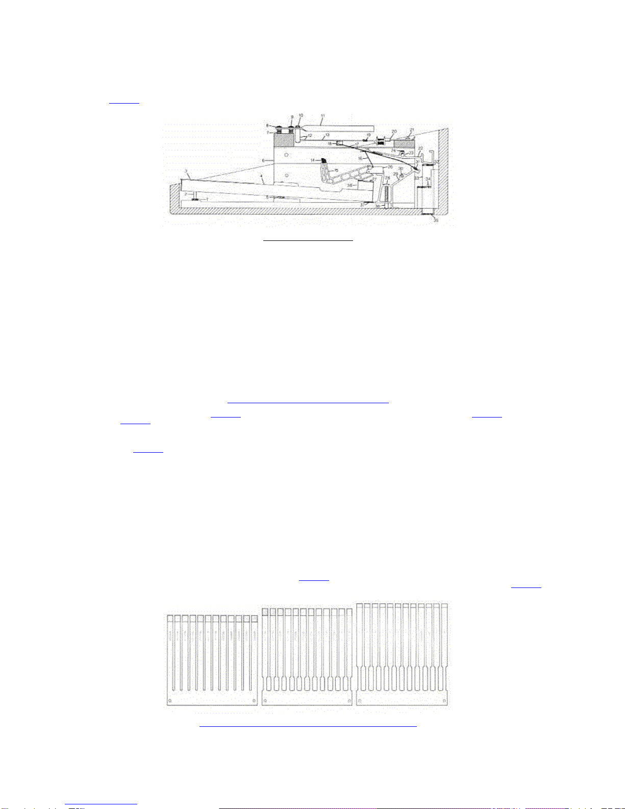
2-2 RHODES Damper Modules - Bass, Mid and Treble Configurations 2-3
2-3 RHODES Modular Action - Exploded View 2-4
3-1 RHODES Harp/Action Assembly - Exploded View 3-2
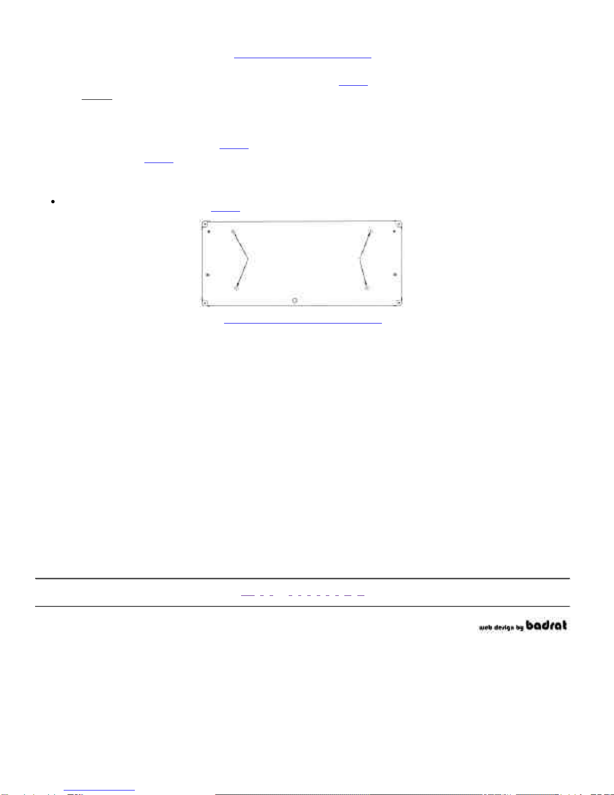
3-2 RHODES Stage Piano - Bottom View 3-3
3-3 RHODES Suitcase Piano Top - Bottom View 3-4
4-1 RHODES Modular Action - Single Key Depressed 4-1
4-2 Escapement Distances 4-1
4-3 Escapement Adjustment Locations 4-2
4-4 Adjustment Location 1 4-3
4-5 RHODES Damper Arm - Tension Adjustment 4-4
4-6 RHODES Damper Arm - Alignment Adjustment 4-4
4-7 RHODES Harp/Action Assembly 4-6
4-8 Timbre Adjustment Diagram 4-7
4-9 Volume Adjustment Diagram 4-7
5-1 RHODES Tone Bar Assembly 5-1
5-2 Harp Position for Tuning the RHODES 5-2
5-3 Typical Dial - Electronic Tuning Device 5-4
5-4 Stretch Tuning Chart 5-6
6-1 Tone Generator Assembly Removal/Replacement 6-2
6-2 Tine Cutting Measurement Chart 6-3
6-3 Felt Strip - Cutting Line Dimension 6-5
6-4 Key Pedestal - Pencil Line Dimension 6-6
6-5 Key Pedestal - 5/32" Felt Piece Mounted 6-6
6-6 Key Pedestal - Felt Modification Complete 6-7
6-7 Key Bushing Tightener 6-8
6-8 Key Identification Chart 6-10
7-1 RHODES First Stage Tone Bar Assembly 7-1
7-2 RHODES Second Stage Tone Bar Assembly 7-2
7-3 RHODES Third Stage Tone Bar Assembly 7-2
7-4 RHODES Original Tine Design 7-2
7-5 RHODES Second Stage Tine Design 7-3
7-6 RHODES Swaged Tine Design 7-3
8-1 RHODES Original Action Design 8-1
8-2 RHODES Second Stage Action Design 8-1
8-3 RHODES Third Stage Action Design 8-2
8-4 RHODES Fourth Stage Action Design 8-2
9-1 Tear Drop Hammer Head - Groove Removal 9-1
9-2 Tear Drop Hammer Head - Reshaping to Striking Line 9-1
9-3 RHODES Hammer - Shim Placement 9-3
9-4 Early Design Damper 9-3
9-5 Double-Shoulder Hammer Head 9-4
9-6 RHODES Early Design Harp/Action Assembly - Cut-Away View 9-5
10-1 RHODES Early Design Single Key View 10-1
10-2 RHODES Early Design Harp/Action Assembly - Exploded View 10-3
10-3 RHODES Original Pickup Coil Series/Parallel Arrangement 10-4
10-4 RHODES Modified Pickup Coil Series/Parallel Arrangement 10-4
10-5 RHODES Bus Wire Re-Routing Diagram 10-4
11-1 Schematic - Preamplifier Assembly - 100 Watt Suitcase and Janus I 11-2
11-2 Printed Circuit Board - Preamplifier Assembly - 100 Watt Suitcase and Janus I 11-3/11-4
11-3 Schematic - Dual 50 Watt Power Amplifier - 100 Watt Suitcase and Janus I 11-5
11-4 Schematic - Power Amplifier - Janus I 11-6
11-5 Printed Circuit Board - +/-15 Volt Regulator - 100 Watt Suitcase and Janus I Power Amplifier 11-7/11-8
11-6 Printed Circuit Board - 50 Watt Power Amplifier - Suitcase Piano 11-9/11-10
11-7 Printed Circuit Board - 50 Watt Power Amplifier - Janus I 11-11/11-12
11-8 Schematic - Preamplifier - 80 Watt Suitcase and Super Satellite 11-13
11-9 Schematic - Power Module - 80 Watt Suitcase 11-14
11-10 Schematic - Power Supply Regulator Assembly (Peterson Design) -80 Watt Suitcase 11-15
11-11 Circuit Board Assembly - Power Supply Regulator (Peterson Design) -80 Watt Suitcase 11-16
11-12 Schematic - Power Amplifier, Master and Slave - Super Satellite 11-17
11-13 Schematic - Power Control Panel, Master - Super Satellite 11-18
11-14 Schematic - Power Control Panel, Slave - Super Satellite 11-19
11-15 Schematic-Converter Kit I 11-20
11-16 Schematic - Converter Kit II 11-21
11-17 Schematic - Preamplifier and Power Amplifier (Jordan Design) -Suitcase Piano (Pre 1969) 11-22
11-18 Connection Diagram - All Printed Circuit Boards - Instructor Console 11-23
11-19 Schematic - Preamplifier and Power Amplifier - Student Piano (First Version - 1968) 11-24
11-20 Schematic - Preamplifier and Power Amplifier - Instructor Piano (First Version - 1968) 11-25

Wednesday, May 24, 2000 Rhodes Service Manual: Table of Contents Page: 3
file:///Macintosh%20HD/Desktop%20Folder/Fender%20Rhodes%20Manual%20%C4/toc.html
11-21 Wiring Diagram - Instructor Console 11-26
11-22 Schematic - Master Circuit Board - Instructor Console 11-27
11-23 Schematic - Power Supply - Instructor Console 11-28
ACKNOWLEDGEMENT
Appreciation is due to all who have been involved in producing this manual. Specifically, to our Sales Force, the Retail and Service dealers and the artists who offered suggestions. Last, but by
no means least, to our own highly qualified Product Development, Production, Service and Marketing personnel whose many hours of labor and years of expertise have produced what we believe
to be a comprehensive aid to servicing and understanding the RHODES Piano.
RHODES Keyboard Instruments U.S.A.
FOREWORD
Since its inception in 1965, the RHODES Piano has remained relatively constant in terms of design concept. However, there have been changes in the methods of achieving those design concepts.
Those concepts which have remained constant throughout the history of the RHODES are:
1. Method of Tone Production. As will be shown in detail, the Tone is produced by a series of modified tuning forks (one for each note) referred to as "Tone Bar Assemblies." Each such
assembly lies adjacent to an adjustable Pickup. The Pickup Coils are all alike and are adjustable as to gap very much as are the points on the Distributor of an automobile. Because of the
unique construction features, each note can be adjusted for Volume, Timbre and Pitch.
2. The Action. Consisting of only three moving parts, the Action is unique in design. While the structure and materials used have changed, the concept has remained unchanged.
This Manual has a two-fold purpose; one, as a maintenance and repair guide; and two, as a detailed description of the various vintage models together with instructions for upgrading and
modernizing the various models wherever possible.

Wednesday, May 24, 2000 Chapter One: The Rhodes Tone Source Page: 1
file:///Macintosh%20HD/Desktop%20Folder/Fender%20Rhodes%20Manual%20%C4/ch1.html
CHAPTER ONE
THE RHODES TONE SOURCE
The unique tone of your RHODES Piano derives from the principle of the tuning fork. While the common tuning fork has two legs of equal length and mass, the tuning forks in your RHODES
Piano differ from these in one very important way (Figure 1-1). The two prongs of our tuning fork are not of the same mass, shape or size. They are alike only in pitch. The lower, more resilient
leg (Tine) responds visibly to the blow of a Hammer by vibrating in a wide arc at a certain frequency.
Figure 1-1. Tuning Fork Comparison
The upper leg (Tone Bar), while not so visible, does vibrate at the same frequency. The importance of this upper leg can easily be demonstrated by the following simple experiments.
1. Strike any note, preferably in the mid-range of the Piano. With the Sustain Pedal down, squeeze the upper leg with the fingers. The tone will die immediately.
2. Perform the same experiment, but this time touch the upper leg very lightly. The vibration will be distinctly felt under the fingers.
This patented concept of the tuning fork offers many advantages (Figure 1-2). One of these is that the upper leg (Tone Bar) supports some pitch variation in the lower leg (Tine). In other words,
assuming G to be the target pitch, the lower leg could be deliberately tuned to F, F#, G, G# or A without any appreciable loss of support from the upper leg. This opens up a world of
possibilities, as will be shown.
Figure 1-2. RHODES Tuning Fork
You will note a small coil Spring on the lower leg so designed as to be a tight fit. This coil Spring acts as a counter-weight and, therefore, as a pitch control. Moving this Spring will result in a
change of pitch. By this means, then, it is possible to arrive at a fine tuning merely by sliding the Spring to the desired spot on the Tine. See Tuning Your RHODES Piano, Page 5-1.
The Tines in your RHODES Piano, like the strings of a guitar, are subject to breakage under stress. We here at the factory are constantly on the alert for ways to achieve the longest possible life in
these as well as in all other component parts of your Piano. In actual tests, Tines picked at random have withstood in excess of 6,000,000 blows in a test machine. This machine is so constructed
as to simulate actual playing conditions. Despite this, steel wire of even the finest quality, invariably has flaws along its surface. If these microscopically small flaws occur in a node point, they
can become the point of eventual fracture. This is offered to explain the fact that, while one person's Piano may play for many years under constant use with no more than a couple or three broken
Tines, another musician may experience a similar breakage within a shorter period of time.
For reasons just described, the Tines cannot be covered in the general warranty of the Piano.
In anticipation of this, we have devised a simple procedure for replacement - one which the musician can perform in about the time it takes to replace a guitar string. Refer to Tone Generator
Assembly Replacement Procedure, Page 6-1.
TOC- 1- 2- 3- 4- 5- 6- 7- 8- 9- 10 - 11
Other manuals for Piano
1
Table of contents
Other Rhodes Musical Instrument manuals

Rhodes
Rhodes 54 User manual

Rhodes
Rhodes Mark 7-73 AM Guide

Rhodes
Rhodes MK-80 Operating and maintenance manual

Rhodes
Rhodes VK-1000 Operating and maintenance manual

Rhodes
Rhodes 73 User manual

Rhodes
Rhodes 54 User manual

Rhodes
Rhodes MK8 User manual

Rhodes
Rhodes Piano User manual

Rhodes
Rhodes Suitcase Piano 73 User manual

Rhodes
Rhodes MK8 User manual