manuals.online logo
Brands
  1. Home
  2. •
  3. Brands
  4. •
  5. Rhodes
  6. •
  7. Musical Instrument
  8. •
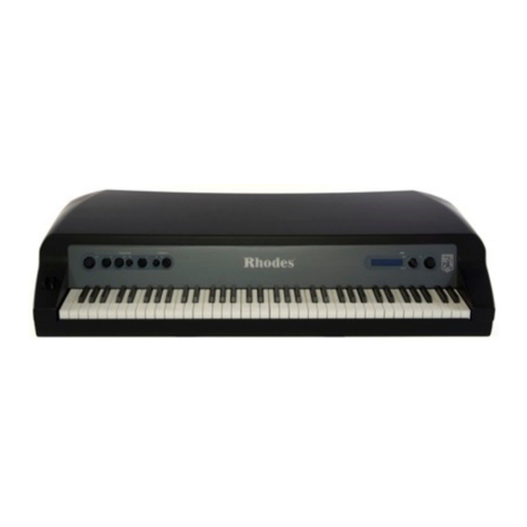
  9. Rhodes VK-1000 Operating and maintenance manual

Rhodes VK-1000 Operating and maintenance manual

Aug. 1991 VK-1000
Rhodes service notes
VK-1000 First Edition
Rhodes ORGAN
TABLE OF CONTENTS mn Page
SPECIFICATIONS
LOCATION OF CONTROLS
EXPLODED VIEW
DISASSEMBLY
BLOCK DIAGRAM
PARTS LIST
KEYBOARD PARTS LIST
KEY DISASSEMBLY
LOADING THE FACTORY PRESET
IDENTIFYING VERSION NUMBER
TEST MODE
DATA SAVE/LOAD
ADJUSTMENT SPECIFICATIONS
"D/A ADJUSTMENT"
MAIN BOARD
SWITCH-A BOARD
CARD BOARD
SWITCH-C BOARD
H-BAR UNITASS'Y
SWITCH-B BOARD
JACK BOARD
POWER SUPPLY BOARD ASS'Y
WITH TRANS BOARD
SK-876-A PCB 32P LOW P-7 ASS'Y
SK-876-A PCB 32P MID P-7 ASS'Y
SK-876-A PCB 12PHI P-7 ASS'Y •••
CHANGE INFORMATION
TROUBLESHOOTING
APPENDIX
1C DATA
STAND RS-80
i±m 1
2, 3
'Mm 3
M^^m 4
7P '7 7(1 5
/t-7 UXF6,7
K/'f-7 UXh7
tmM^^m 8,9
77" 7hU-•7° U-t -y h(7)P -9
9
x7 F•^-K9~11
x-7(D-tz-7/P- K11-13
mm±m “D/Atm" 13
MAIN BOARD
SWITCH-A BOARD
CARD BOARD
SWITCH-C BOARD
H-BAR UNITASS’Y
SWITCH-BBOARD
JACK BOARD
POWER SUPPLY BOARD ASS’Y
WITH TRANS BOARD
SK-876-A PCB 32P LOW P-7 ASS’Y
SK-876-A PCB 32P MID P-7 ASS’Y
SK-876-A PCB12PHI P-7 ASS’Y- •
Fy7/F '> ZL —7" <>7'
1C x-7
77>KRS-80
14, 15
16
16
16
17
18, 19
20,21
22
23, 24
23, 24
23, 24
25
26, 27
28
29
30
(^Roland 17059613 Printed in Japan (AGEO) (CR) 1
SPECIFICATIONS/f±ti
©Keyboard 76 Keys, Eto G, with Velocity
©Sound source Adjustable SA Synthesis
©Maximum Polyphony 16
©Memory capacity Internal :64 Patches
Memory Card (M-256E) :64 Patches
©LCD Display 240 x64 dot backlit LCD
©Output Level -F4dBm insetting: power on settings, slider controllers: min,
l^volume: max, 8Keys on, percussion: normal
©Pedal Expression pedal :0V(0) -5V(127)
Assignable pedal 1:0V(0) -5V(127)
Assignable pedal 2:0V(0) -5V(127)
Assignable pedal 3:OV(0) -5V(127)
©Consumption 20W (100V, 117V)
25W (230V, 240V)
©Dimensions •••• 1255(W) x520(D) x115(H) mm
49-7/1 6(W) X20-1/2(D) x4-1/2(H) inches
©Weight 22.0 kg /48 lb 8oz
©Accessories Owner's Manual Set (Japanese) :26045511
Owner's Manual Set (English) :26045512
AAC Cord (Detachable/I^#jt)
100V (DC-01 5-J01) :23495112
117V (UC-704-J01) :1 343981 2F0
220V (EC-21 0-E06) :1 343981 3F0
240VE (5722-660-4606) :23495110
240VA (SC-41 5-J06) :1 343981 4F0
Audio Cable (PJ-1M) .**^f**^**
©Options RS-80 (Stand)
M-256E (Memory Card)
RH-12/100 (Stereo Headphone)
DP-2R/6R, FS-5U (Pedal Switch)
EV-5/10 (Expression Pedal)
PK-5 (Dynamic MIDI Pedal)
VK-1000 Aug. 1991
LOCATION OF CONTROLS//N°t
NO. PARTS NUMBER PARTS NAME
©22495272 Key Top 4P (window) 249-272
©22495279 Key Top 3P (window) 249-279
©22A9B271 Key Top IP (window) 249-277
15029380 SLR55VC80F215 TP LED
22495271 Key Top 4P 249-271
22495276 Key Top 3P 249-276
©13169697 SKHVBD 100G tape Tact Switch
32485261 Slide Knob 248-261
1[22225366 Escutcheon 222-366
@1
22245472 Pot Dust Cover 224-472
113339960 RS3011 Slide VR
32485222 H-Bar Knob 1248-222
32485223 H-Bar Knob 11/3 248-223
®32485224 H-Bar Knob 13/5 248-224
32485225 H-Bar Knob 2248-225
32485226 H-Bar Knob 22/3 248-226
32485227 H-Bar Knob 4248-227
32485228 H-Bar Knob 51/3 248-228
32485229 H-Bar Knob 8248-229
32485230 H-Bar Knob 16 248-230
13339959 RS40D113A H-Bar Slide VR
22225364 Escutcheon S222-364
22225363 Escutcheon L222-363
®1
[22045324 Display Cover 204-324
[15029483 TLX-711A-30TA1 LCD Unit
NOTE: Replacement LCD Unit should be made on aunit
bassis.
No replacements available for individual parts.
Replacement only by aunit.
ft :LCD Unit 'y hCl ^oTT $
122200188 Card Holder 220-188
122205603 Card Holder 220-603
13429679 AF3LS-PG-RT CANNON Connector
®13429274 YKF51-5041 MIDI Connector
13449145 YKB21-5010 Jack
13449146 YKB21-5012 Jack
®13449275 YKB21-5074 Jack
13449252 YKB21-5006 Stereo Jack
®13159354 SSSP12 Slide Switch
®23275892 PB-A0102 327-892 Pitch Bender
NOTE: Replacement should be made on aunit bassis.
No replacements available for individual parts.
Replacement only by aunit.
ft :-y
A® 13149108 WK2A44 Power Switch
2
Aug. 1991 VK-1000
EXPLODED VIEW/5^fl?H NO. PARTS NUMBER PARTS NAME
7625639000 Power Supply Board assy (pcb 22935102) ®22225458 Top Panel 222-458
with Trans Board (D 22225457 Front Panel 222-457
[1® 7625690000 Main Board assy (pcb 22925931) 121125502 Side Panel L112-502
7625634000 H-Bar Unit assy (pcb 22935101) ®121125503 Side Panel R112-503
07625608000 Switch-A Board assy (pcb 22925997) ®22235334 Blind 223-334 ^»i1
®7625611000 Switch-B Board assy (pcb 22925998) ©21135248 Bottom Board 113-248 ^-)K2
®7625618000 Switch-C Board assy (pcb 22925997) ©22515110 Badge 251-110
07625631000 Jack Board assy (pcb 22925999) ©22125340 Plate 212-340
®7625607000 Card Board assy (pcb 22925997) 122205606 Side Holder L220-606 —i^^l
23275892 PB-A0102 327-892 Pitch Bender ^122205605 Side Holder R220-605
NOTE: Replacement should be made on aunit bassis.
No replacements available for individual parts.
Replacement only by aunit.
H: :-3-— -y hc: ^oXT $
lillm'ili, -3-ji.y h-HMvlo
Q)
^1:
^2:
22205604 Center Holder 220-604
22205615 Holder 220-615
22205601 Trans Holder 220-601
22465927 Heat Sink 246-927
22455641 UO Power Transformer
22325140 Hinge 232-140 (Prior to SNo.ZC81049)
22325154 Hinge 232-154(SNo,ZC81050-up/m)^^2
22125690 ANGLE 212-690 ^^2
7625620000 Keyboard (76Key) SK-876A
Shape changed for SNo. ZC80950 and up with compatibility.
Shape changed for SNo. ZC81050 and up but^^wi^^
compatibility.
Parts of new shape are supplied as repair parts. When
changing the Bottom Board and/or Angle of the VK1000
having SNo. ZC81049 and down, the Bottom Board, Angle
and Hinge must be changed at the same time. Note that
parts of old shape are available for the Hinge oniv.
•)K 1
JK 2
10 L,
fit, T.m±ML^j:(DXiX
SNO.ZC80950
SNO.ZC81050 IjlPf
SNO.ZC81049 IXWiX) VKIOOO (D Bottom Board, Ang^le
TZ) p^[l. Bottom Board, Angle, Hinge ^L-tTT $
V^o {H-L. Hinge It t±,
3
DISASSEMBLY/^ll^^lli
©Top Panel Removal Screws
4x20mm Truss Be
Aug. 1991 VK-1000
BLOCK DIAGRAM/7
VK-1000 Aug. 1991
PARTS UST//\°-yU7^ h
SAFETYPRECA UTIONS:
The parts marked Ahave
safety-related characteristics.
Use only listed parts for
replacement.
:
to
tiZ
LTTSOo
CONSIDERATIONS ON PARTS ORDERING
When ordering any parts listed in the parts list, please specify the following items in the order sheet.
QTY PART NUMBER DESCRIPTION MODEL NUMBER
Ex. 10 22575241 Sharp Key C-20/50
15 2247017300 Knob (orange! DAC-15D
Failure to completely fill the above Items with correct number and description will result in delayed or
even undelivered replacement.
n—'V icn "S’ §33SI 1
1
7t— hlTlS. *TTIB®4I!
'id WS; ®—'V
m) 10
llTIEfi ;eautt$o„ (Whsko
22575241 Sharp Key
2247017300 Knob 'Orange''
C-20/50
DAC-15D
mb >Main Board assy SCB
SAB >Switch-A Board assy SBB
CB >Card Board assy JB
-
HBU >H-Bar Unit assy PSB
>Switch-C Board assy
>Switch-B Board assy
>Jack Board assy
>Power Supply Board assy with Trans Board
CASINGZ-ir-X
22225457 Front Panel 222-457
22225458 Top Panel 222-458
22235334 Blind 223-334
21135248 Bottom Board 113-248
22125340 Plate 212-340
22515110 Badge 251-110
22225366 Escutcheon 222-366
22245472 Pot Dust Cover 224-472
22045324 Display Cover 204-324
22325140 Hinge 232-140
22325154 Hinge 232-154
22205604 Center Holder 220-604
21125503 Side Panel R112-503
21125502 Side Panel L112-502
22225364 Escutcheon S222-364
22225363 Escutcheon L222-363
CHASSIS/v^
22205605 Side Holder R220-605
22205606 Side Holder L220-606
22205615 Holder 220-615
22205602 Main Holder 220-602
22205650 Display Holder 220-650 SAB
22205601 Trans Holder 220-601 PS Unit
22465927 Heat Sink 246-927 PS Unit
22200188 Card Holder 220-188 CB
22205603 Card Holder 220-603 CB
22205607 Jack Holder 220-607 JB
22355491 Bass 235-491 HBU
KNOB,BUTTON/yv5
,
22495272 Key Top 4P (window) 249-272
22495279 Key Top 3P (window) 249-279
22495277 Key Top 1P(window) 249-277
22495271 Key Top 4P 249-271
22495276 Key Top 3P 249-276
32485261 Slide Knob 248-261
32485222 H-Bar Knob 1248-222 on HBU
32485223 H-Bar Knob 11/3 248-223 on HBU
32485224 H-Bar Knob 13/5 248-224 on HBU
32485225 H-Bar Knob 2248-225 on HBU
32485226 H-Bar Knob 2 2/3 248-226 on HBU
32485227 H-Bar Knob 4248-227 on HBU
32485228 H-Bar Knob 51/3 248-228 on HBU
32485229 H-Bar Knob 8248-229 on HBU
32485230 H-Bar Knob 16 248-230 on HBU
SWITCH/X<
A13149108 WK2A44 Power Switch PS Unit
13169697 SKHVBD 100G tape Tact Switch SAB, SBB, SCB
13159354 SSSP12 Slide Switch JB
13159137 SSSS21067A Micro Switch MB
JACK, SOCKET/VN"7 'i7 ,'J 'r "7 V
13429679 AF3LS-PG-RT CANNON Connector JB
13429274 YKF51-5041 MIDI Connector JB
13449145 YKB21-5010 Jack JB
13449146 YKB21-5012 Jack JB
13449275 YKB21-5074 Jack JB
13449252 YKB21-5006 Stereo Jack JB
13429543 100-032-001 1C Socket 32P MB
DISPLAY UNIT/S^cl -yh
15029483 TLX-711A-30TA1 LCD Unit
NOTE: Replacement should be made on aunit bassis.
No replacements available for individual parts.
Replacement only by aunit.
'/-H 1t—7h®o"C hSB''o
POWER SUPPLY UNIT/gigJ. -yS
7625638100 PS Unit (100V)
7625638200 PS Unit (117V)
7625638400 PS Unit (230V)
7625638500 PS Unit (240V)
BENDER UIMIT/a:>^ -j.- 7h
23275892 PB-A0102 327-892 Pitch Bender
NOTE: Replacement should be made on aunit bassis.
No replacements available for individual parts.
Replacement only by aunit.
/K :JL- yhK$t\.
III! (linn li, tl® /h'i'fVo
KEYBOARD/affi^B£n°n
7625620000 Keyboard (76Key) SK-876A
NOTE: Refer to the "KEYBOARD PARTS LIST SK-876A "(P. 7) for details.
ff. :“KEYBOARD PARTS LIST SK-876A” (P.7) Lr'K $t'o
PCB ASSY/*tS^fi!cp'?i
[e] 7625690000
7625608000
7625607000
7625618000
7625611000
7625631000
7625634000
7625639000
Main Board assy
Switch-A Board assy
Card Board assy
Switch-C Board assy
Switch-B Board assy
Jack Board assy
H-Bar Unit assy
Power Supply Board assy
with Trans Board
(pcb 22925931)
(pcb 22925997)
(pcb 22925997)
(pcb 22925997)
(pcb 22925998)
(pcb 22925999)
(pcb 22935101)
(pcb 22935102)
15199747 HD6475328F CPU ZTAT (H8/532) MB
15199746 HD6435328F CPU MASK (H8/532) MB
15209259 LH530800 MASK ROM parameter MB
15209260 LH 530800 MASK ROM Wave AMB
15209261 LH 530800 MASK ROM Wave BMB
15209262 LH 530800 MASK ROM Wave CMB
15179444 LC3764P MASK ROM (programed) MB
15179734A0 AM27C191ACP OTP MB
15209204B0 M5M27C101K-15 1M EPROM (blank) MB
15449262 M5M27C101K-15 1M EPROM (Ver.1.00) MB
15449269 M5M27C101K-15 1M EPROM (Ver.1.01) MB
15449278 M5M27C101K-15 1M EPROM (Ver.1.02) MB
15229837 MB60VH 142PF-G-BND Gate Array MB
15229838 MB60VH 141PF-G-BND Gate Array MB
15229839 MB61VH 125PGF-G-BND Gate Array MB
15239142 M60014-0149FP Custom 1C MB
15239147 HG62E11R23FS Gate Array MB
15235149 HG62E11B24FS Gate Array MB
15239124 SSC1000 Custom 1C MB
15239120 TC23SC260AF-002 Custom 1C MB
15239170 R06-0011 Gate Array MB
15279508 HM62256LFP-12SLT SRAM MB
15259701 TO TC74HC00F-T2 HS-CMOS miniflat MB
15259704T0 TC74HC04F-T2 HS-CMOS miniflat MB
15259706T0 TC74HCU04F-T2 HS-CMOS miniflat MB
15259708T0 TC74HC08F-T2 HS-CMOS miniflat MB
15259865T0 TC74HC4053F-T2 HS-CMOS miniflat MB
15259720T0 TC74HC74F-T2 HS-CMOS miniflat MB
15249105 TC74AC74F-T2 HS-CMOS miniflat MB
15259734T0 TC74HC132F-T2 HS-CMOS miniflat MB
15179362H0 HM50464P-12 DRAM MB
15179445 CXK5814P-45 RAM MB
15289107 M5218FPSOP-TP OP.AMP MB
15289106 M5238FPSOP-TP OP.AMP MB
15289117 NJM5532M SO TP OP.AMP MB
15259885 TC7532FTE85L-TP 1C MB
15209189 PCM1700K-T2 D/A Conberter MB
A15199251 TA78L005PTPE-6 +5V V.RGL MB
A15199172 TA79L005P TPE-6 -5V V.RGL MB
A15199117 M5230L Power 1C PSB
A1 51 99244 PQ05RR1 V.Regulator PSB
A15199108N0 UPC78M05H V, Regulator PSB
15169552T0 TC74HC245P C.MOS SAB, SBB
15159704T0 TD-62084AP Tr. Array SAB, SBB
15149134 TD-62785P Tr.Array SAB, SBB
15189242 NJM4565SD Op.AMP SAB, JB
15169596 TC74HC4051 HC.MOS HBU, JB
15189231 NJM4565D OP.AMP HBU
15169305H0 HD74LS08P TTL JB
15229718 6N137 Photo Coupler JB
15219186 M5207L-05 VCA JB
15189519 NJM5532S Op.AMP JB
15189190 M5216L Op.AMP JB
TRANSISTOR/ h7>v/. ^-
15309101 2SA1037KRT-96 Chip Tr. MB
15319105 2SC3326ATE-85L Chip Tr. MB
15319101 2SC2412KRT-96 Chip Tr. MB
15329502 DTC-124EKT-96 Chip D-Tr. MB
15329503 DTA-124EKT-96 Chip D-Tr. MB
A15119814 2SB 1015-0 Power Tr. PSB
A1 51 29834 2SD 1408-0 Power Tr. PSB
151291410S 2SC-1740S Tr. HBU
15129600 2SD-571L Power Tr. JB
15119601 2SB-605L Power Tr. JB
15129198 DTA-124ES-TP DTA JB
15129197 DTC-144WS-TP DTC JB
15119159 DTA-114ES DTA JB
15129136 2SC2878-A Tr. JB
15119129 2SA1 115-E Tr. JB
15129140 2SC2603-E Tr. JB
15119113 2SA1015GR Tr. JB
D\ODE/Sf'(t- K
15339105 DAN202K T-96 Chip Di MB
15339103 MA-153 TP Chip Di MB
15339114 RB420D T-146 Chip Di MB
A15019170 D5FB20 4002L15 Di Bridge PSB
A1 501 9283 DSF-10BT Di PSB
A15019103 1S-2473 Di PSB
15019125 1SS-133 Di
15019153 1SS-176 Di
15029380 SLR55VC80F215 TP LED SAB, SBB, SCB
RESISTOR/fifil
13299178 RHE0A150RA Trimer MB
13919308M0 RGLD 6X10³J Resistor Array MB
13919140 RGLD 8X10³J Resistor Array MB
13919251 RGLD 10X103J Resistor Array MB
13919200 16B-10Z-ME1 Rader Network MB
15399917 MNR34J5A103E Chip RA MB
15399932 MNR34J5A101 TP Chip RA MB
15399904 MNR34J5A333E TP Chip RA MB
13919162M0 RGLD 4X1 04J Resistor Array SBB
13919142 RGLD 8X1 04J Resister Array SBB
A1 37691 61 TO MR25N 1% 100PPM 3.3K PSB
A1 37691 77T0 MR25N 1% 100PPM 15K PSB
A1 37691 80T0 MR25N 1% 100PPM 20K PSB
POTENTIOMETER/;}t Vel-
13339960 RS30111 Slide VR SAB
13339959 RS40D113A H-Bar Slide VR HBU
CAPACITOR/ >T>-y—
13529230 CXKD 4X101
M
Network 10OP X4MB
A13529104 DE7150F472MVA1 Linebypass Capacitor PSB
A13659208 SME16VN10000 Block Capacitor PSB
A13659226M0 ECET35R472SW Block Capacitor PSB
INDUCTOR, COIL,FILTER/OX XX, 7t;LX-
A1 2449229 FK0B-160MH15 Line Filter Coil PSB
12449383R1 FBR07HA850TB00 Ferrite Bead SAB
12449369 PFB-2 4502-069 LC Filter MB
13529187 ELKTT391CA Digital Noise Filter MB
Al 2449323 ESD-R-25SD Data Line Filter PSB
CRYSTAL, RESONATOR/
15299132 MA-506 20.000MHZ TP MB
15299140 MA-506 20.48M TP MB
15299150 SG-531 49.152M MB
FUSE, FUSE HOLDER/ ti-X, ta.-X
Al 2554585 19198-400MAT Fuse 5x20 400mA 250V PS UNIT (100V, 117V)
Al 2559560 CEE-200MAT WICKMANN Fuse 5x20 200mA 250V PS UNIT (230V, 240V)
Al 21 99550 H0446 Fuse Clip PSB
CONNECTOR/H^^7 X-
13429233 7508095A 1C Card Connecter CB
13439527 53014-0310 (3P) 2mm Pitch Con. MB, JB, PSB
13439528 53014-0410 (4P) 2mm Pitch Con. MB, JB, PSB
13439529 53014-0510 (5P) 2mm Pitch Con. MB, JB, PSB
13439530 53014-0610 (6P) 2mm Pitch Con. MB,JB, PSB
13439531 53014-0710 (7P) 2mm Pitch Con. MB,HBU, JB, PSB
13439532 53014-0810 (8P) 2mm Pitch Con. MB,JB, PSB
13439533 53014-0910 (9P) 2mm Pitch Con. PSB
13439534 53014-1010 (10P) 2mm Pitch Con. MB, HBU,JB
13439535 53014-1110 (IIP) 2mm Pitch Con. MB
13439537 53014-1310 (13P) 2mm Pitch Con. MB
13439538 53014-1410 (14P) 2mm Pitch Con. HBU
3369701 IL-FPC-16S-SITI-SBNSUMI (16P) Card Con. MB
13369700 IL-FPC-20S-SITI-SBNSUMI (20P) Card Con. MB
13429366 5332-20GS1 (20P) Flat Cable Con. MB
13429367 5332-40GS1 (40P) Flat Cable Con. MB,CB
13429355 53015-0510 (5P) 2mm Pitch Con. SBB
13429261 53015-0810 (8P) 2mm Pitch Con. SBB
13429356 53015-0910 (9P) 2mm Pitch Con. SAB
13429351 53015-1010 (10P) 2mm Pitch Con. SAB, SBB
13429357 53015-1110 (IIP) 2mm Pitch Con. SBB
13429358 53015-1310 (13P) 2mm Pitch Con. SAB
13439374 5483-06AX (6P) 2.5mm Pitch HBU
6
Aug. 1991 VK-1000
WIRING, CABLE/7-TT
23485714 W1-1 (8P) PSB-MB
23485715 W1-2(6P) PSB-MB
23485716 W1-3(5P) PSB-MB
23485717 W1-4( 5P) PSB-JB
23485718 W1-5(9P) PSB -SAB
23485719 W1-6(7P) PSB-MB
23485720 W1-7(7P) PSB-JB
23485721 W1-8(4P) PSB-MB
23485722 W1-9(3P) PSB -LCD
23485723 W1-10(6P) Board in PSB -TRANS
23485724 W2-1 (14P) Board in SAB-HBU
23485725 W2-2(10P) SAB- HBU
23485726 W2-3 (6P) Board in SAB- JB
23485727 W2-4(13P) SAB -MB
23485728 W3-1 (10P) Board in SAB -SBB
23485729 W3-2 (8P) Board in SAB -SBB
23485730 W3-3(11P) SBB -MB
23485731 W3-4 (5P) SBB -MB
23485732 W4-1 (7P) Board in SCB-HBU
23485733 W5-1 (10P) JB-MB
23485734 W5-2 (8P) JB-MB
23485735 W5-3 (4P) JB-MB
23485887 W5-4 (3P) JB-MB
23485736 W6-1 (40P Flat) CB-MB
23485737 W7-1 (20PFIat) LCD -MB
23485838 J1-1 PSB -TRANS
23485832 J1-1 (117V) PSB -TRANS
23485739 J1-2 PSB -Pow.Sw.- INLET
23485831 J1-2 (117V) PSB -Pow.Sw.- INLET
23485859 J2 Stay
TRANSFORMER/ h7>
A22455641 UO Power Transformer
AC INLET/OUTRET/AC -f >UyKU 7h
A134297 18 CM-11 (3P) 100V, 240V
A134297 10 PA-126 (2P) 117V, 220V
BATTERY/«>4
A12569249S0 CR2032 Litium Battery MB
12569420 Battery Holder for CR2032 MB
SCREW/tvli
#****#* 4x12 mm Truss Be
******** 3x8 mm Binding Be
******** 4x20 mm Truss Be
******** 3x6 mm Tp Bind B1 Be
******** 3x8 mm Tp Bind B1 Be
******** 3x8 mm P-TightCm
******** 3x8 mm B-Tight Binding Cm
******** 4x20 mm Tp Truss B1 Be
******** 4x8 mm P-Tight Cm
******** M3 Speed Nut
MISCELLANEOUS/^
12449609 Inverter Module NI03-05-5 PSB
22175320 Spring 217-320
22175318 Panel Spring 217-318
ACCESSORIES/Hip^JiS^
2604551
1
Owner's Manual set Japanese
26045512 Owner's Manual set English
A23495112 DC-01 5-J01 100V AC Cord (Detaehable/SSiif'f j'i;)
A1343981 2F0 UC-704-J01 117V AC Cord (Detaehable/fljdff j't)
A1343981 3F0 EC-2 10-E06 220V AC Cord (Detaehable/id.iiTj'i;)
A23495110 5722-660-4606 240V-England AC Cord (Detaehable/)J(i;t''fy';;)
A13439814F0 SC-415-J06 240V-Australia AC Cord (Detaehable/)j(i>i''i A)
OPTIONS/3'J§6fn
........ RS-80 STAND
NOTE: Refertothe "STAND RS-80 PARTS LIST" (P. 30) for details.
a:ffilii, “ST..\ND RS-80 P.^RTS LIST" (P. 30 )$:#!!«, LTK5
KEYBOARD PARTS LIST/=^^--1< -K/\°-7U7 h
No. PARTS NUMBER PARTS NAME
©22575349W0 NATURAL KEY C/F
22575348W0 NATURAL KEY E/B
22575350W0 NATURAL KEY D
22575351 WO NATURAL KEY G
22575347W0 NATURAL KEY A
22575352W0 NATURAL KEY E7B'
22575354W0 NATURAL KEY G'
(D 22575355W0 SHARP KEY
@22815806 CHASSIS 76P-A ASSY
NOTE: CHASSIS 76P-A ASSY includes the
following 3parts.
:CHASSIS 76P-A ASSY (±, rB<D 3
Si“o
22815792 CHASSIS 76P-A
22265494 FELT A76KEY 226-494
22265530 CUSHION 76P-A
022155909 GUIDE BUSH 215-909
22125690 ANGLE 212-690
7625621000 SK-876-A PCB P-7 ASSY
NOTE: SK-876-A PCB P-7 ASSY includes the
following 3parts.
:SK-876-A PCB P-7 ASSY (±, 3
7625622000 SK-876-A PCB 32P LOW P-7 ASSY
7625623000 SK-876-A PCB 32P MID P-7 ASSY
7625623000 SK-876-A PCB 12P HI P-7 ASSY
©22185253 RUBBER SWITCH 12P
22185254 RUBBER SWITCH 13P
22185252 RUBBER SWITCH 8PL
22185251 RUBBER SWITCH 7PL
32205597 PCB SPACER 12P
32205598 PCB SPACER 13P
32205596 PCB SPACER 8PL
32205595 PCB SPACER 7PL
22135445 76P STOPPER-A 213-445
22135446 76P STOPPER-B 213-446
23475370 FUJI CARD 12X70-A6.0BB-H10 PI. 25
23475343 FUJI CARD 16x380-A5.0BB-P1.25
23475344 FUJI CARD 20x380-A5.0BB-P1.25
22365101 MINI FLAT CABLE CLIP LFC-30N-O
******** SPRING
******** 3x1 0mm Binding Head Tap tite screws Btite
******** 3x 8mm Binding Head Tap tite screws Btite
7
VK-1000 Aug. 1991
KEY DISASSEMBLY
1. INSTALLATION OF RGB'S 1.
Parts required/'JZ'WSr^p^
PARTS No. PARTS NAME
7625622000 SK-876-A PCB 32PLOW P-7 ASSY 1
7625623000 SK-876-A PCB 32PMID P-7 ASSY 1
7625624000 SK-876-A PCB 12PHI P-7 ASSY 1
22185253 SK-8 RUBBER SWITCH 12P 4
22185254 SK-8 RUBBER SWITCH 13P 1
22185252 SK-8 RUBBER SWITCH 8PL 1
22185251 SK-8 RUBBER SWITCH 7PH 1
32205597 SK-8 PCB SPACER 12P 4
32205598 SK-8 PCB SPACER 13P 1
32205596 SK-8 PCB SPACER 8PL 1
32205595 SK-8 PCB SPACER 7PH 1
TAP TITE SCREWS B-TITE 3x10 BIND 40
1
)
First, turn the chassis over, noting that the right- and
left-hand sides are not reversed.
Then, as shown in fig. 1, put one Spacer 8PL and four
Spacers 12P in this order, starting on the left-hand side
(lower tone side of the keyboard) according to the
chassis positioning holes. (See fig. 2.)
Similarly, put the Spacer 13P and Spacer 7PH on the
right-hand side (higher tone side).
1)t-f, ^^J; AL
t-to
fig.i (oji-r J; ^(zAiliPJ (lic7)fi(;r,M![iJ) J; h,
vtT SPACER 8PL ^111*1, ^LT SPACER 12P ^4
fW ,'> -V -VC74 fv: [I',; ik jllfi (C I'TV^
(fig,2 #]!hC)C i;
)
trffl (’rWitHi) SPACER 13P, SPACER 7PH ^
S-To
Lower tone side
mwi Higher tone side
i' 'j IVfSPJ
2)
Then, locate the bosses of the Rubber Switches in the
round holes of the Spacers, and as done for the
Spacers, put one Rubber Switch 8PL, four Rubber
Switches 12P, one Rubber Switch 13P and one Rubber
Switch 7PH in order, starting on the lower tone side.
At this time, carefully match the positions of the
Rubber Switches, Spacer notches and air grooves.
(See fig. 3and fig. 4.)
2)^kiz, SPACER (Z)A/xi^^lZ RUBBER SWITCH 04^'
X
LX, SPACER <h J: ^)MUz
RUBBER SWITCH 8PL, RUBBER SWITCH 12P ^4
i|S|, RUBBER SWITCH 13P, RUBBER SWITCH 7PH
ffiX ^TV^^^"t'o
RUBBER SWITCH <h SPACER hX
ItnT, J: ^(Cv;1-:aj; ut <fz
(fig.3 fig.4 (L )
"Notches
fig. 4
3)
Then, put the PCBs so that the positioning pins of
the Spacers fit into the positioning holes of the
PCBs. At this time, use the PCB notch and Spacer lug
as aguide. (See fig. 5.)
As shown in fig. 6, there are three PCBs, LOW, MID
and HI.
Chdssi
k\—k
3)A\z, PCB (X>m SPACER gTp tL
T, SPACER tf X(7 PCB ^k
1iZ PCB kiS ^-ito (fig.5 t) .
PCB ii, fig.6 X'Tji^tl^J: 1LLOW. MID. HI (0 3
4)
Then, tighten the LOW, MID and HI PCBs with the
Tap Tite Screws. First tighten the near-center Screws
1, then the end Screws 2on the other side. (This
order must be followed. Otherwise the PCBs may
not be flush with the Spacers.)
Then tighten the remaining Screws 3of the LOW,
MID and HI PCBs. (For the above, see Fig. 7.)
Finally, tighten the Screws in the area adjacent to the
MID and HI PCBs.
Since the PCBs may have been warped by soldering,
etc., it is recommended to gently hold down the
center and tighten the Screws.
4)X(7, TAP TITE SCREWS "C PCB LOW, MID, HI
C.lh^ J-fo
*9 1ki2LiLA> L,
AiZlkMUm 2Ltto (17 J: oX,
PCB MSPACER J; X/T § TLSD-t^
fzA>o)
gf^l7 PCB <D MID, HI (DmiMf^ki2L±i6Lti-o
SSSXVN>X#1t^l7 J; oT VUkALX^^^^bL t
tJx^XL J: -9 o
8
Aug. 1991
2. REMOVAL AND REINSTALLATION OF THE KEYS 2.
Before removing the keys, first take the stopper off the J ^ A> Xhy/N” —
rear side of the chassis, then take away the spring. 'yVUt'T'LX,
When reinstalling the keys, carefully apply the stopper *'} (i, fig.8 C/5 $J: ^Xh—
as shown in fig. 8. C){j; *9 LT <( C$
Bring the stopper into close contact with the ends of Xhyti SI®ttn|5C)Vh''}'# f'J tt, fAllfU'C —
the white key shafts and press the stopper in the area 7°Ji io $CCzE $-C T<( /j: $v^o(fig-8
The above is aview from the rear side of the chassis.
Ht± ^h^fzmxto
LOADING THE FACTORY PRESET/7
h
U-•7'Jtr yhWP-
©Press IWRITE |to call the Write Menu screen (Pressing
IWRITE Icalls the Write Menu screen from any ©IWRITE IiWLX y^h -^
t(Iwrite I^
i©)o
Press IF3 |iii?Hi to open the Initialize Menu screen.
Press [fUEszai to open the Cold Boot screen.
ICOLIi BOOT :Hr eyou
nFSliTJTil -®UiJ
75$-fi-S ©o
f~F4 ]Essa ^#LTn-K•X'- hMtfii ^-^7j< $X
ti~o
COLD BOOT
i:enter.--e;>=;it:i|
0To execute the Cold Boot, press |
I. To cancel it.
in Pressing |ENTER |causes the screen to show the
same indication (Welcome Message) shown when the
unit is switched on. The Cold Boot procedure will be
completed when the unit has automatically returned
to the Play screen.
0n-;l/ K•X- ht^(i IENTER |X^
tli IEXIT IXlf LiXo
[71 IENTER IiW-tt,
A•^-yX-X) <tf XX T
^tn-XK•X- ht^Xo
IDENTIFYING VERSION NUMBER//^- vX
Note: The version displayed is of the CPU (IC22 on Main
Board) and EPROM (IC18 on Main Board). For
details, see the CHANGE INFORMATION (P. 25).
1. In the batch play mode, hold down the [IN
and IDEC jbuttons and press the |NUMBER
INUMBER/21,INUMBER/31,|NUMBER/4],
INUMBER/51,IBANK/7 |,|NUMBER/61and
INUMBER/3 Ibuttons in this order.
v£ •A/X $“X3X(i, CPU (IC22 on Main Board)
<h EPROM (IC 18 on Main Board) CO^COXXo
(P. 25)
1. /Xy XXXT"E -KX IINC IXX ><h IDEC jXX >
INUMBER/ 11,INUMBER/2I.
INUMBER/3I.INUMBER/4I,INUMBER/5I,
IBANK/7 I,INUMBER/^,jNUMBER/sl X>MXX
VK-1000
2.When in the test mode, the version number of
the ROM is first displayed. The process then
moves automatically to the next step. Note that
the version number of the ROM Ver. 1.00 is not
displayed.
3. Switch the power OFF. 3. “OFF”
2. 7~ XhX—KXA^It ROM O/'—X3>’
X>7S'-^^XLSXo
gfilWX, iat, ROMCOz-^'-XX
X'XX7-N —$XXV^^o^^XX', X
tUi, Ver. 1.00 X'Xo
TEST MODE/X7 -K
OEquipment Required
•FV-50 (volume pedal)
•EV-5 (expression pedal)
•MIDI cable •Oscilloscope
•Memory card
(M-256E, etc. of which data may be erased)
•Measuring jig (see fig. 1) •Empty plug
Fig. l/m 1
ommt^t(D
•FV-50 (X'J i“A•/5XX),
•EV-5 (X. XXXX-y X3X•^XX ),
•MIDIX-XX, •XXnxrj-X,
•X0-•-K
(M-256E^ :
•(mi #.0S), •X
This type is mono open plug.
ZtUi, XX^XxX'XXo
OEnlering the Test Mode <C>x"X —K^(7)AU^
Enter the thst mode in either of the following two ways: AX h•A— K"^X)A *9 TISX) 2ii 00^Xo
1. Start-up from the panel
In the batch play mode, hold down the [\
IDEC Ibuttons and press the [NUMBERTT
INUMBER/21,INUMBER/3I,INUMBER/41,
INUMBER/51,IBANK/7 j,|NUMBER/61and
INUMBER/3 Ibuttons in this order.
1.
yf- XXTX-KX [INC
INUMBER/ ll,
INUMBER/3I,INUMBER/4~
IBANK/7 I,INUMBER/61,
XX XiIDEC !XX X^
NUMBER/2I,
,INUMBER/5],
INUMBER/3 IXjl|I X
X
2. Start-up from the Main Board 2. MAIN BOARD (XXA, ©If
Set the mode switch (SW2: see fig. 2for its position) MAIN BOARD XV)A— KX TyA(SW2 :M
on the Main Board to the "TEST" position and 2#HS) ^“TEST” fJUAgj 0#AXSiJ® A“ON” X
switch the power ON. LtiTo
9
OLeaving the Test Mode
1.When the test mode has been started up from the panel
When all tests are complete, switch the power ON
again.
2. When the test mode has been started up from the
Main Board
Set the mode switch (SW2: see fig. 2 for its position)
on the Main Board to the "NORM" position and
switch the power ON again.
Xh“ON” izL
2. MAIN BOARD Y±M'
MAIN BOARD ±(D^- K'X ^-y 7(SW2 :fvliKili, 1?<J
2#.HS) “NORM”
“ON” 7L'CT^V^o
OCheck Items
The VK1000 includes the following eight check items
and one adjustment:
TEST 1: Identifying ROM version
TEST 2: Switch and LED check
TEST 3: Memory card check
TEST 4: Harmonic bar check
TEST 5: Controller and pedal check
TEST 6: MIDI check
TEST 7: Battery check
TEST 8: D/A adjustment mode
TEST 9: VCA check
For the checking procedures, see the corresponding
check items.
TEST 1: Identifying ROM version
Note: The version displayed is of the CPU
(IC22 on Main Board) and EPROM
(IC18 on Main Board). For details, see
the CHANGE INFORMATION (P. 25).
When in the test mode, the version number of
the ROM is first displayed. (See fig. 3.) The
process then moves automatically to TEST 2.
Note that the version number of the ROM Ver.
1.00 is not displayed.
xy
VKIOOO TililW 8tI
TEST 1:ROM V3yWU
TEST 2:XTyXRIYLED X9
TEST 3:^^'J -“K•7iVX
TEST 4:-y •7^ vX
TEST 5:X>hn-y-XX
y
x
TEST 6:MIDI -T i-y X
TEST 7:X'j -•-Ti -y X
TEST 8:D/A pjf^"e- K
TEST 9:VCA T- i-y X
X- yff ')i it: (i ,^X- i-y XR^LXX
TEST 1:ROM v3
it 'y3yhi, CPU (IC22 on
Main Board) <h EPROM (IC18 on Main
Board)
(P. 25)
T" Xh-T" —K(C Aifri WAROM X) ^73
>.xyx~^m<ttto (lxl3#J!d)
TEST itt, ROM
(7) yS' —V3>•XyV' ^X)
Ver. l.OOA'i-o
ROM Ver l.u2 Rg. 3/03
TEST 2: Switch and LED check
1. Press the |NUMBER/1 |button.
2. After making sure that the rNUMBER/T] button
LED is lit, press the |NUMBER/1~| button again.
This lights up all LEDs. At this time, check that
all LEDs are lit and identical in brightness.
3. In the state of step 2, press the fNUMBER/1 |
button. This causes its LED to be extinguished
and the name of the button displayed on the
LCD to be highlighted. (See fig. 4.)
4. Press all buttons in order and make sure
that the characters of the corresponding
button name displayed on the LCD are
normal. If so, the check is complete.
5. With the |NUMBER7i~| button LED off, press
the INUMBER/T] button to leave the test
mode. In this state, any of the check items can
be selected using the corresponding number
button.
TEST 2:XT-y XRZ/LEPAj. -y X
1. INUMBER/
n
7X>Aj'l|l Lii"o
2. Inumber/FI aX>CD led UT
I
A, ^D-UiL INUMBER/ 1IAX>=
XtLED X'XXXM LtXo -cDII/f, I
bo Ai -y XUTT$'
3. Affi 2.INUMBER/
n
AX>^
A<h LED ;6Afj'j:r L, LCD $fifz
:
yx>Xm X'bC$XMx c-titXo (ixJ 4#J!(
4.AT CD AX X4-# LA, LED (D'/i'j'Lr, I
(c AA $tL AAX>CD At DJ
XXtUfX i-y XTA.
5. INUMBER/ nAX>cD LED UTl
T,INUMBER/^ AX>At'l' At,
(DA -KAbAAt ,Xy•AX:
XX. yXJJl R4" b(7 h^Ao
VK-1000 Aug. 1991
I
I
iPN.ySiEP./R
CfiRDlUP-snl
PTCHlUPPRiLOWRlPEDLlED IT|WR I
T
Fig. 4/|H 4
TEST 3: Memory card check
Note: When the memory card check is made,
the data on the card is converted into
check data. Hence, it is suggested to
use acard of which data may be lost.
1. Press the |NUMBER/^ button.
2. Any of the following messages is displayed on
the LCD according to the state of memory card:
TEST 3:XAN-:X-K-Ai'yX
it :XAL-A-K•Ai-y X^AVt-K
(DA- XAA j- -y Xffl(7#§^A 19 ^AcD
T, AcDA- XAAAtiT A-KXr
UTT^A.
1.INUMBER/2I AX XAff Lt Ao
2. XA'j -A-KcDl4;t^ AJ: ^,LCD ATE
Card protect is ON.
Card does not exist.
Card protect is OFF.
[PROTECTED !]
[NO CARD] (See fig. 5.)
[STANDBY CARD] [OK]
(See fig. 6.)
KAnrX hON AHf
t-KA'tei/
A
KAnrX bOFFWU#
[PROTECTED !][**]
[NO CARD] (@5#M)
[STANBAY CARD] [OK]
(E16#.B?,)
MEMORY CRRD CHECK!
[No Card! ]
[5k)K ]
MEMORY CARD CHECK!
[Standby Card ]
[OK ]
Fig. 5/|i] 5
TEST 4: Harmonic ba rcheck
1. Press the |NUMBER/3 |button.
2. Move each harmonic bar and make sure
that the level of the corresponding
harmonic bar changes between 0and 127.
(See fig. 7.)
At this time, the tone of C4 is generated
when the harmonic bar is moved. Press
the C4 key to stop the tone.
H-ERR TE:5T
F<='^='t.
Iex C127:
51X3’ C127:
C127:
4- CI 27 :
22..-3=' C127]
Fig. 6/lH 6
TEST 4:^^-A.::: 7X^-^'“ 'Ai -y X
1.INUMBER/31 AX X^#LS Ao
2. A- -y X•IrillA LT, XfUZ
—A— -y X•X) U0
-127 ^?IELTT$Ao (0
7#0S)
3(DB#, C4 (D-T/6A^-
A
-
7
X
AU/LA#AT^^|^Lt Ac (C 4(Dmm^W
19 iAo
Percussion
C1273
C1273
C127]
[1273
C127D
C127]
E:1273
C1273 Fig. 7/Hj 7
TEST 5: Controller andpedal chec k
1. Press the |NUMBER/^ button.
2. Make sure that the master volume, control
slider, pedal and modulation values
change between 0and 127 and the bender
value changes between —127 and +127.
(See fig. 8.)
[CONTROLLER TEST
TEST 5
Master UR C127D E:xpr ess ion
:51 ider Cl C127: Pedal PI
SI ider C2 C1273 Peda 1P2
SI ider i~:X C127: Peda 1P3
Eender C03 Modu 1at ion
uXFn-y-RlF^XXX X. 7X
1.INUMBER/4I AXx^ff Ao
2.“7XX —-ADyL- A, nxhn —A-x
XTX" —,^X" A, AAjL X—3X(D\UX,
0-127, AXX"-(DfgA', -127 -A127
(xnx^itx^^t^miLxx^^x (0
8:^BS)
Fig. 8/m 8
10
Aug. 1991
TEST 6: MIDI check
1. Connect the MIDI IN and MIDI OUT
terminals by the MIDI cable.
2. Press the |NUMBER/5 |button.
3. Any of the following messages is displayed
on the LCD according to the state:
TEST 6:MIDI -T i-y ^
1. MIDI y-TDET:', MIDI IN tMIDI OUT ^
2. INUMBER/sl 9>iWLt-fo
3. Xh, LCD
and OUT ternninals not connected.-*- [OPEN] (See fig. 9.)
and OUT ternninals connected. -« [OK ]
MIDI ?irT-(7) IN ^OUT [OPEN] (M 9#!!«)
MIDlST-OIN^OUT^Mirt^ -^ [OK ]
MIDI TEST NOW!
COPEN ]Fig. 9/m 9
TEST 7: Battery check
1. Press the |NUMBER/6 |button.
2. The LCD displays the voltage of the user
memory backup battery. (See fig. 10.)
Note: Anormal voltage value is 2.7V or
higher. Change the battery if the
voltage is less than 2.7V.
TEST 7:^'^'y -A U-•7^ ^-y ^
1. INUMBER/61 ^
2. LCD ±U, ^‘y^ry
(IKIIO
#JTh )
ii-. :2.7V T:T±4' hJE'i\-:X'to 2.7V J: U1'(D
BRTTERY CHECK I
F3- 1VI
COK 3
Fig. 10/E110
TEST 8: D/A adjustment mode
1. Press the |NUMBER/7 |button. The LCD
displays as shown in fig. 11.
2. Adjust the D/A converter.
For full information, see the "D/A
ADJUSTMENT SPECIFICATIONS" (P. 13).
;D/Ai^^^- K
1. INUMBER/?]
LCD -r'T X7°U T(T, laiUD TD
2. D/A n
imii, “D/AlHSttli” (P. 13)
D/fl TUNE NOW!
Fig. Il/mil
TEST 9: VCA check
1. Press the |NUMBER/8 |button. The LCD
displays as shown in fig. 12.
2. Output the VCA checking sine wave.
At this time, move the master volume and
make auditory check to see that the right-
and left-hand side volumes are output at
the same level.
If they are different, check the Jack Board.
TEST 9:VCA yy
1. INUMBER/sl ^^WLt-fo
LCD -r' TX7°U T(T, 1K112(7) TA
flt-fo
2. VCA T-i -y Li-to
7(DU#, VX #-•
—(D U^)V^' iVi Jj ^ilX
LrT$V
Jack Board
-y #L-rr$k^o
VCfl CHECK NOW!
Fig. 12/IH12
VK-1000
DATA SAVE/LOAD/x-^<D1r-7/P- K
Press IF4 |l:fiTH[4u Jin the Write Menu screen to open 7Th•ya. —|F4 |UfAlHLiUJiW't ty
the Backup Menu screen. #Ty7° •Ajl —§J"#0
The Backup Menu screen allows you to select one of the /''' -y 7T-y 7° •7—j. —Miljt:', @L-
^
five functions; "#0 5o(/)]§ 111 TR'C ^J"#0
IFI IUSQ The Internal -* Card screen.
IF2 I^^91 The Card -Internal screen.
IF3 IQBIQIQ]] The Internal —*• MIDI screen.
IF4 IfiMMMiTl The Card -* MIDI screen.
IF5 IThe Temporary-*- MIDI screen
T-MIDI
C-MIDI
I-MIDI
C-l
l-C
INTERNAL —CARD y(7-K)
CARD —INTERNAL (;(/ -K—T77-9-/L)
-K(D^7- 7^l^fM U-(T7 7-7-/L) (-1%
'i.'i'o
INTERNAL -MIDI (BULK DUMP) (^P^-tA-MIDI (UDL^7">7°))
77-#-;u)co^T“7 V-7-7-1J--
^-y 7T-y Ltt 7*7"
>7°)o
CARD -MIDI (BULK DUMP) (:/; -K—MIDI (/UL7 •7"7 7°))
7^U-•77 -K•Xn.y h-F<7)^
-r-7^, '>-7-X+h-^ -y 7T-y 7°lt^(7
(^'^7L7 •7"X7°)o
TEMPORARY ^MIDI (BULK DUMP) (r >4^7 'J MIDI (/UL7 •7>7°))
Xd/ 7U—-y X•t—7
-7- X+L “^-y 7T-y Ltt
(/s';U7 •7"X7°)o
INTERNAL -CARD
This function allows you to save all data in the internal
memory onto aMemory Card.
CARD —INTERNAL
This function Allows you to load all data on acard back
into the internal memory.
INTERNAL— MIDI (BULK DUMP)
This function allows you to transfer all data in the
internal memory into an external backup device (such
as asequencer). (Bulk Dump)
CARD— MIDI (BULK DUMP)
This function allows you to transfer all data on the
Memory Card connected to the card slot to an external
backup device such as asequencer. (Bulk Dump)
TEMPORARY- MIDI (BULK DUMP)
This function allows you to transfer the Patch data in
the Temporary area to an external backup device (such
as asequencer). (Bulk Dump)
TX7--U7U— 7; -Kfflffi
7; -K—TX7--7
TX7--7 IL —MIDI ®li to
7-K—MIDI ®® -to
7X7° 7UMIDI ®ffi to
OHow to save all the data in the internal memory
onto aMemory Card
©Connect aMemory Card to the card slot (MEMORY
CARD).
©Set the protect switch on the Memory Card to the
OFF position.
©Press IWRITE |to call the Write Menu screen
(Pressing |WRITE [calls the Write Menu screen from
any screen).
0Press IF4 |:?*!»> ttna to open the Backup Menu
screen.
Oti-
®7-K•xn -y h(MEMORY CARD) (7 7-7 u-•7-
Ktto
®77U--7-K(D7°n'77h •xT-y7^77(TU
tto
©Iwrite! LT. 7# h•7
tt (Iwrite] ^WLX ^
0tt)o
0[F^ r^TirnTii 7r-y 7° •7^^-0®
11
(5) Press |FI ||^S9 to open the Internal -* Card
screen.
(D IFI IlgM y9^ij~ Klliij'liif
-to
(D To transfer the data, press |ENTER |.To cancel
transfer, press |EXIT |.
0In afew seconds after you press |ENTER |,the
message "COMPLETE!" will appear in the screen
showing that the card backup procedure is
completed.
(7) Return the protect switch on the Memory Card to
the ON position, then remove the card from the card
slot.
(6) ^^ti: IENTER |
t§tAIEXIT I
[71 IeNTERI LT Ufh <t^t, COMPLETE !
Lt Lfz) t-fo^ fi-Xrij -
y9T yLtLfZo
(7) •ii -V(Dy°u9' 9h•v^^t'ylzU
L, iJ --Y'yu y
<C>How to load all the data on acard into the
internal memory
©Connect aMemory Card to the card slot (MEMORY
CARD).
to call the Write Menu screen.
e1calls the Write Menu screen from
any screen.)
©Press IF4 |to open the Backup Menu
screen.
0Press IF2 |^BD to the Card —Internal
screen.
O*-Y'(D±zr- ^
©-K•Xn-y h(MEMORY CARD) (I ^^'j -•i]
-
i©o
@IWRITEI vT h•^-JL
t-t (IWRITE ILT ^C.(Dli[&HC
^^i©)o
®I
F
4liiTiTtfoni "} 9yy'f 'y=- ^-liwii
i©o
®[mBHD LX k-Y-i y9-i-
To transfer the data, press
transfer, press |EXIT |.
.To cancel
[7] In afew seconds after you press |ENTER |,the
message "COMPLETE!" will appearin the screen
showing that all the card data is loaded into the
internal memory.
®Remove the card from the card slot.
®$sii^©©©^ ^§ti: IENTER |©-v>-t;L©^
t#(j: |EXIT| ^#L^©o
IeNTErI LT LifO <©^ COMPLETE I(|z;
LtLfz) S©o CfiX'k -
Y<D-r~ 9tit Lfzo
®9! ~Y^k ~YXU yS©o
OHow to transfer all the data in the internal Op*3nP-^ ^—^y7^ y
memory into an external backup device
©Connect the MIDI OUT on the VK-1000 to the MIDI IN ©VK-1000 (D MIDI T9 ht^<y 9T y©1t§|(D MIDI
on the backup device using aMIDI cable. T>1©O MIDI ©—LS©
(This is called aOne-way connection.) •7j. T<hP77^i©)o
VK-1000 Aug. 1991
©Press IWRITE |to call the Write Menu screen
(Pressing |WRITE |calls the Write Menu screen from
any screen).
©Press IF4 1l:yi.TW!!ilJJ to open the Backup Menu
screen.
0Press IF3 |mkMIiH to open the Internal -* MIDI
screen.
©IWRITE I7T h•
ti- (IWRITE I©jf LT ^CcDljffill
©’0 ^©)o
@IF4iWLX^-^y 9Tyy° •X^jl -®ffi
©^©$©^ ©o
0IF3 lIHliMl ©ftp t-c T>7-©;L —MIDI ®ffi©
^©$©^ ©o
Note: When the transmission data range has been ©:jUjf©^ 7L© 0MC-500MK2 ©
determined, make the MC-500MK2 ready to ©TT $
receive data.
®<MC-500MK2> ®<MC-500MK2>
Turn the MC-500MK2 power on, and the following MC-500MK2 COMM'^ Xtl'i'f'o MC-500MK2 Ot 9
display will appear. ^
Insert System Disk
and Press ENTER
®<MC-500MK2>
Insert the SUPER MRC system disk, and press the
key to start up the SUPER MRC system.
®<MC-500MK2>
SUPERMRC©'>X©A©^X7©A©, IENTER I©-
©#LT, SUPER MRC C0'>X©A©5:-^±If^ ©o
©<MC-500MK2>
Make sure that the following display appears. ©<MC-500MK2>
TiScDJ: ^Xm^s^tl^(D^mULtto
SONG 1
M=1 J=120 REAL
SONG 1: Song number V>'©-©X7'n —
M=1:Measure /J^Sp
J=120 :Tempo ©X©
REAL :Recording mode Urr —K•T: —K
®<MC-500MK2>
Use the cursor keys |•«- || -» |to remove the cursor to
the Song number.
©<MC-500MK2>
Specify the Song number in which to save the data,
([numeric keypad] -[SHIFT] key +[ENTER] key)
(0 <MC-500MK2>
Press the [REC/LOAD] key. The following display
will appear, and the MC-500MK2 is ready to receive
bulk data.
®<MC-500MK2>
©-y©•©-[3,H©. y©©yy©•©
y/S' -(7) fig #fjj $©t©
o
®<MC-500MK2>
©-©©U-y"$©^y y© •©y/s'- ©fg^Ui©,
([©y •©-]—[SHIFT]© -©[ENTER]©-)
®<MC-500MK2>
[REC/LOAD] ©-©ftp LS©o
19, /©L© ’r~9'§:im^mtWS9f^
'Otto
Press PLAY >> RECORD
M=1J=120 REAL
12
Aug. 1991
(0 <MC-500MK2>
Press the [PLAY/SAVE] key.
The MC-500MK2 will enter Recording mode, after a
little while, so transmit bulk data from the VK-1000.
(S) Start receiving on the external backup device (start
recording on the sequencer).
[71 When you use asequencer featuring aMIDI filter,
set it to the mode that can receive Exclusive
messages (On the Roland MC-50, set the MIDI 2RCV
STATUS to ON).
(T|) To transfer the data, press IENTER I. To cancel
(0)To transfer the data, press |ENTER |.To cancel
transfer, press [EXIT |.
[7]In afew seconds after you press |ENTER |,the
message "COMPLETE!" will appear in the screen
indicating that the back up procedure is complete.
(0)Stop the external backup device (Stop the recording
on the sequencer).
®<MC-500MK2>
When the VK-1000 has finished transmitting bulk
data, press the |STOP |key to exit Recording mode.
®<MC-500MK2>
For the sake of safety, we suggest that you save the
received bulk data to disk. To save to disk or load
from disk, refer to the "SUPER MRC" Owner's
Manual.
This completes data reception.
^Transferring data (MC-500MK2 ==> VK-1000)
©<MC-500MK2>
Use the |a-dial |or (|numeric key "1 "~| +|ENTER |
KEY) to select the first measure.
(D The VK-1000 may be in the normal mode (play mode).
NOTE: VK-1000 does not display any message
when receiving bulk data. After receiving
bulk data, temporary data will not be edited.
If you want to display the patch edited,
select other patches first, then select the
edited patch.
(D <MC-500MK2>
Press the |PLAY/SAVE |key.
@<MC-500MK2>
Press the [STOP |key to stop the sequencer.
(When bulk data transmission ends, the sequencer
will automatically stop, and the measure will blink.)
This completes bulk data reception.
©<MC-500MK2>
[PLAY/SAVE]
^
Lt-fo
MC-500MK2 ^3--rV >/S CO-X:, 'P LI0
VK-1000
®MP y(v-
\J} MIDI y'(
^>2) 1#© yy y'tuiiz ^PiiiX
^^X0Xt^^LX^I^x <(n-v> KMC-50
2RCV STATUS ^t>(©xA£L^-r)o
®^ti: IENTER |
t§(j; IEXIT I
[7] IENTER I^WLX LlXh <COMPLETE !(fe
LtLfz) t-fo XtL-CAI-
y^Ty ximpmr ltltzo
®^y yr yy°W^X>pit hyP^Xrt-t ('>-
y-'y^~(7)Kzi~rx yy'iy hyX^-itt-t)o
©<MC-500MK2>
VK-1000 ^•X-Y4- fit L7o7
^,ISTOP IX-iWLX, yofkpMPikif
tPo
®<MC-500MK2>
‘^i'^L/z^-ixy 'T- yIt, 7jp—y)fznb, xxyy
iz-t-y"LXto <XXX yy^(D
P~y"tfz{t, U-VCOpikit, “SUPER MRC” COM
(MC-500MK2 ==> VK-1000)
©<MC-500MK2>
Ig-Dial Itfzit (IX'y-X~“l^ +IENTER I7-) 7
'dX
K(7°UT
P:VK-1000 it, XX y.-r- y
yyX—'y PiTf. XiX: X
o
•X~yp\0
'ikx, X'ypy 0-•r~yim^i^ty7 t-itXo
yx^m^i^xfzmmx-mxL/zxmrY,
yXtXHCOy^ yXXMtKLX, MX, 1*r
^i^XfzXyX^mtKLXr^iX
©<MC-500MK2>
IPLAY/SAVeI 7-
©<MC-500MK2>
|STQP| 7-^1f LT, 'y~X'yp-^ ih.V)ti-o
(/SAP 7r- yCD lilt L/zhS ^
<0 ,L^©o
)
yxAzx, x'xy •r- y(Dpini^j
o
ADJUSTMENT SPECIFICATIONS "D/A ADJUSTMENT"/IIOIIf±fll “D/Al^ll ”
Adjust both the Land Rchannels.
This adjustment may be mode in either of the following
two ways.
A) Adjustment looking at the waveform on the oscilloscope
B) Adjustment using auditory perception
L, RWiX^ 'yxxxtiXt^^XT-^C'
TiecD to
A) tyuyy-ylziO im^XkixmW.
B) mmxx 19 ms
^y(Dmrxmt,
VK-1000
A) Adjustment looking at the waveform on the oscilloscope
a) Connect the oscilloscope into the [LINE OUT] jack
of the channel to be adjusted.
Insert the blank plug into the jack of the channel
not adjusted.
At this time, set the MASTER variable resistor to
the maximum position.
*Oscilloscope setting
5mV/div, Imsec/div, probe setting of 1:1.
b) In the test mode, select the "TEST 8, D/A
adjustment mode".
For the setting procedure, see the "TEST MODE"
(P. 9~11)
c) Looking at the oscilloscope, turn the corresponding
semi-variable resistor (VR 1=L channel, 2=Rchannel.
Positions are shown in Fig. 2) on the main board until the
waveform as shown in Fig. 1appears.
A) tXu yzi~ylzX 7l&MX ^xm^
a) [LINE OUT] -y 77
t'> n7rj -XXWiTiLXr^cy
-V >XXCO'y ^yy(Lti,
^y°y xi^Lk^xxtc^xT^cx
*t'yuyzi~t(Dt^^
5mV/div, Imsec/div, 7°n —y'lil i1
b) XyV -“TEST 8, D/Afl^-T- K” \Z
IxTEXXt^Xo
“xy h•X~ K” (P. 9~11)
.0SLTT$Va
c) 7'>nxr7-7°^E©©'0, 01<D J; a
MAIN BOARD ±<D©E1^ (Lch =VR2,
Rch=vRi :fig©, 02#F,?.) xmxxm^Lx
Befor adjustment/©iiJfi^ Befor adjustment/^ilJfM After adjustment/pilM
Fig. l/m 1
B) Adjustment by auditory sense
a) In the test mode, select the "TEST 8, D/A
adjustment mode".
For the setting procedure, see the "TEST MODE"
(P. 9~11).
b) At this time, the D/A adjustment sine wave is output.
c) Listen to the sine wave output from the "LINE
OUT/L" jack and adjust VR2 on the Main Board (see
fig. 2) until noise is minimized.
d) Similarly, adjust VR1 on the Main Board (see fig. 2)
using auditory sense.
B)SIS© j;
a)-rX h•KCD “TEST 8, D/Afl^T-- K” X
txrn(D-Xmt, “xyv •K” (P. 9~11)
b) D/Afi)M©7
c) [LINE OUT/L] -7
ykXim
(I MAIN BOARD (D VR2 (0 2#M)
d)[LINE OUT/R] kMBtX MAIN BOARD
(DVRi (0 2#0?j xm^t^o
13
VK-1000 Aug. 1991
is# i
i-^sses i%# 1fi
I'"'
.I,,-
El MAIN BOARD ASS^Y
ASSY 7625690000
(pcb 22925931)
1C33 '’•t
iiilifiilliiilllll
HI«®0464P')2 IfMiiTIll
.0464P-12
HM50464PM2
-'HM50464P-I2
tA42RA4t RA4aRA39-*5/:*!
2a
-RA44 RA43
«****m1
+IM50464P-12
r#(5a464P
Hiil
cits R93PB2C1ieao'
r3EJ
BTLar
View from component side
/——For Nordic Countries'
Apparatus containing
Lithium batteries
ADVARSEL!
Lithiumbatteri -Eksplosionsfare ved fejiagtig
h^lndtering.
Udskiftning mS kun ske med batteri af samme
fabrikat og type.
Lever det brugte batteri tilbage til leveranderen,
ADVARSEL!
Lithiumbatteri -Eksplosjonsfare.
Ved utskifting benyttes kun batteri som anbefalt
av apparatfabrikanten.
BruW batteri returneres apparatleveranderen.
VARNING!
Explosionsfara vid felaktigt batteribyte.
Anvand samma batterityp eller en ekvivalent typ
som rekommenderas av apparattillverkaren.
Kassera anvant batteri enligt fabrikantens
instruktion.
VAROITUS!
Paristo voi rajahtaa, jos se on virheellisesti
asennettu.
Vaihda paristo ainoastaan laitevalmistajan
suosittelemaan tyyppiin. Havita kaytetty paristo
valmistajan ohjeiden mukaisesti.
14
Aug. 1991 VK-1000
mMM BOARD ASS^Y
TO SWITCH BBOARD
CN4
TO SWITCH BBOARD
CN3
TO JACK BOARD
CN5
TO JACK BOARD
CN3
TO SWITCH ABOARD
CN3
&neo
I,I100
,1C230 VDD
’74HCU04J R102
RAQ 100X4
RAB 100X4
TO CARD BOARD
CN1
6332-40031
^R07
VCC
1-J- C147
-r°-’
mC148
T""
AIN OUT P—4
Ifi6 C42
70LO6 10/10
VDO
03 tl IZC2B
RS2 lot J'2
/lUTE
CONTROL
MUTE
MUTE
PCB-292-931-00
.PCB_-_292-93 1-Ql
VDD
XC36B FBR07 C120 •
74HCU04 I/
b
,N0
-•IN
tIt
jj R7^| ^C| ^
IC1A mm
^ua
—
-z
Z53F
C164
0.1
iSf IC1
A.: IV
LPF .^^cp
hITb h
.M0INla-aKLi^s^ Ns-1
^IN OUT -KJ
008 000 l(,,o si !:r3 i
ptnLa *0^® ^
NJM8B3a
TO JACK BOARD
CN7
TO JACK BOARD
CN2
TO P.S BOARD
CN9
03014-0710
FROM PS BOARD
FBH07
^CB0 47/0.3
TO KEYBOARD
KEY
SCAN
-VCC ^BR07
TO P.S BOARD
CN5
TO P.S BOARD
CN7
74HC08
’0140 2.2U
TO KEYBOARD
TO P.S BOARD
CN2
TO P.S BOARD
CN4
0142 0133 002 040 020 020 027 020
0.1 0.1 0.1 0.1 0.1 0.1 0.1 0.1
15
VK-1000 Aug. 1991
21 22 2S 24 2i AI'li xJ // AA- -'i" rV" '' r- /' r' <"' *
C' \C,r' r''r.'.:/«s. :
V' ^V,^ V. *v
ASSY 7625608000
(pcb 22925997) ASSY 7625618000
(pcb 22925997) ASSY 7625607000
(pcb 22925997)
‘r^4:
—:"ir -:*yt4'**' '
..7
—
.;'%-v '".. ..—
“
'-J7~"“‘ ^>^<.-CN3 .I
i...TI., ,.
'
,,r- •J8 "" J9^ -~'„-
@: r
::i 'r--T/1 6(/ -? ^mncyc '*
""©I (@)' \\ ‘'
S\
"X- vT-,rK”“” ‘-V/ ^>V>. *r >.aA
-yy' ,:ya^ yy
ufr '®''
ypI
.!1jI9 .* .\BHJ20 ^:'
I;••' //// J.."••
c.Cyy4'X^x/ty
^-.II'^ ^TTJ^Tit-.^ r.-„! 'p |\ «’ ^.| i]
{:t ,_S,°S(!:
I
1U| RA
I
:r •tv -1--(yji -'"'y' ,i^
Ofj; u^-y- o..y 7)j o.^-j-._T3i ->i •("*- JI 3
i i ,
'^'-=
\.L¥
-P :i~N cvl: y^r---jix 5
/"'s li iii
^¥y,
r>^
j" C6 -Hh“,
rm\: 4~4;mh
y@>:':;; W-yi
yy«Q];^;s;
C8
.©) i@;
oyrr. iswi.
—
¥Oy-.. Ir ,'''
U23 /.
m
ysw2 /
,Di9v y~'
RHODES VK-1000
SWITCH-C BOARD
“ySSY 76256180 00
„
;®:
“'L
J3. wl>3'
'1 10
{ i "02
4y'>
u~V
'' (*) r-'
«|yS| g
tMADE IN JAPAN ‘"—03-
lKTG-R2V-0a,^
(@J
8—CN5 ;,‘4'^- ISH
y, N\\V^^N --
;«ris‘44y. >'m ,L1.^ -/y~ :
-^'y>
<- y
:y:-
'
('(~
-05 ,l-i=i”-
SW6*
'm (@)
,= ,s;, 4ry~j:
11—11^r
^F5-
i»? JO
I
'¥i!!|
-"1 o>J 7<: 1'^
;-. S133
*<zson
7r2o
AI^orr*
Jlilice/
yf>iO/il 4
.
Ii
Ii-Allliit-
1
1
1
IV'.S•SH'JV
@®;
O>-J 0)
?>5°eS
S^ggQ.
MODES VK-1000
S\WITCH-A BOARD
i'tdkk ^QS3(i0isU OQ ;
ASSY 76256080 00
'MADE IN JAPAN"
KTG-R2V-0a.^
ili)
(y1345
VJ43' JI
c-
y'S
INC \
W:n
'C'rWt)
DI6-"
y•®;,
SWITCM-A BOARD ASS'Y
VREF D.+BV A.+12V
B3015-1010 TO H-BAR
CN2 TO H-BAR
CN4
SWlTCH-C BOARD ASS'Y
View from component side
A. -12V I
VR1 1VR2 1VR3 1VR4
10KB. 10KB ,10KB .10KB J
>^3 -J>..3^ <>^3 .>
^T<
J<
JLx i
Cl* 'C2' C3'
O. 1O. 1O. 1
RIGHT LEFT
KX2 R3 1
R4 _L C8 ioo
470K •
n
0.GND D.GND R2
\XI A A • 4I
R1 I±C6
470K >
n
D.GND D.GND
TO SW B
CN1
HBAR
>-0 0-* '
DEC
i-O 0-* '
DOWN >-0 0-' '
PERC -0 0-* ‘
BEND H-O O-i
DRAW ^C2 /
D6 1
SW6 ^1
SW7 ^D8 T
SV^ ¥DO Jf
SV^ ^D4 T
SW4 ZDIO T
SW10 iD5 1
SW5 ^
-0 oJ
F2 >-o bJ
F3 H-o bJ
F4
1-0 0-1
F5 —
0
0-1
EXIT -0 oJ
ENTER
L-o 0-1
FI SCjLy
D12 1
SW12 i
-0 oJ
D1^
SW16 YDI 4T
SW14 Z
-o"°"oJ
DI 3I
SW13 ^
-0 oJ
GREEN
BLUE
BROWN
ORANGE
RED
YELLOW
TO H-BAR
CN3
VR1 MODULATION
D+5V 4
D.+5V 5
D.GND 6
D.GND 7
DiGND
W3-2 ITO SW B
CN2 BENDER UNIT
CARD BOARD ASS'Y
|H|CAg
1121 CA7
Vo/^B
U^C9 4
L_lq-
1
L3 -CIO m
-0.1 IMl3 C12
47/6 .
3
A. GND LI
L1-B: FBROB
TO MAIN
CN7 5332-40GS1
IC CARD CN
TSOBOGBA
TO PS
53015-0010 ^9|B|7|6|5|4|312|1
TO MAIN
53015-1310
Aug, 1991 VK-1000
VR4 VH13
10KB tOKfl
74HC4051
GND
D.GND
56K 6BK
IC3A I
rr
RQ
XO
XI
\
R
4
11/3
\
R
5
13/5
D
R
6222/3
T
R
84
—
R
8B
R
1
°B1/3
.L,Lx;,L.LXI
VK-1000 Aug. 1991
I
SWITCH-B BOARD ASS^Y
ASSY 7625611000
(pcb 22925998)
Mggiiil—glllii
N,2«L.
RHODES Vk-IOdO SyyitCH-B BbARp'
it. ASSY 7625‘6iio;;oo;;.;:: [
IN japan.
KTG-R2V-6A
SW29
SW27 SW28*
Sw4
:s:w3tf SW3’t'
SW12
SW1 0
SW9
SW35
S'\A/20
SwipT 5W19
View from component side
18
VK-1000 Aug. 1991
i*p1**•>
im#'
JACK BOARD ASS^Y
ASSY 7625631000
(pcb 22925999)
;}i;
^Roland
RHODES VK^
ipilllpilf
.t“3! ^BOARD
mmm ASSY 76256310 00
M‘ad| in japan
'KTo-to-OAm ^
Pplili
F1.I.I;;
'.» f*t_ »». «»_«'_ « I
fsm:
P.,CJ8
•1 »"**
iilli' liiiipfiiliiiiiiPip
*r-55ti iH''*W‘'*v*r’*e4*n, %*w.**w
*;;•D7, 1^“*+*: :^9‘ ^*1
:
*/*: i'"•• *f’ *iR8^; '”R85° .y9Q- '"
*lS"*f^!
iiilii
115-1
:
fI'll
iiiiiiiiii*
Cl C.J
U( u'
a>i -nJI
B86
apiwiltis
iis •;'*<''
W|R68'
liStt; JKI2
(siiiSiii!
TJ^[’"'a—
U*-"’ ^mr-
i}
jfer -A [
i’^
'
t'?
l^;'’ ’Aqi £z
2
Ki'S-nii 1
View from component side
20

Other manuals for VK-1000

1

Other Rhodes Musical Instrument manuals

Rhodes Piano User manual

Rhodes

Rhodes Piano User manual

Rhodes 73 User manual

Rhodes

Rhodes 73 User manual

Rhodes VK-1000 User manual

Rhodes

Rhodes VK-1000 User manual

Rhodes Mark 7-73 AM Guide

Rhodes

Rhodes Mark 7-73 AM Guide

Rhodes 54 User manual

Rhodes

Rhodes 54 User manual

Rhodes Suitcase Piano 73 User manual

Rhodes

Rhodes Suitcase Piano 73 User manual

Rhodes Piano User manual

Rhodes

Rhodes Piano User manual

Rhodes MK-80 Operating and maintenance manual

Rhodes

Rhodes MK-80 Operating and maintenance manual

Rhodes 54 User manual

Rhodes

Rhodes 54 User manual

Rhodes MK8 User manual

Rhodes

Rhodes MK8 User manual

Rhodes MK8 User manual

Rhodes

Rhodes MK8 User manual

Rhodes V8 User manual

Rhodes

Rhodes V8 User manual

Popular Musical Instrument manuals by other brands

Percussion Play Freechimes Diatonic Symphony installation instructions

Percussion Play

Percussion Play Freechimes Diatonic Symphony installation instructions

Suzuki Digital Grand Piano owner's manual

Suzuki

Suzuki Digital Grand Piano owner's manual

Roland RS-09 owner's manual

Roland

Roland RS-09 owner's manual

Yamaha Clavinova CVP-105 Service manual

Yamaha

Yamaha Clavinova CVP-105 Service manual

Yamaha YT-280D owner's manual

Yamaha

Yamaha YT-280D owner's manual

Lowrey Cadet EZ3 owner's guide

Lowrey

Lowrey Cadet EZ3 owner's guide

Dynatone SLP-200H owner's manual

Dynatone

Dynatone SLP-200H owner's manual

Roland HP-307 owner's manual

Roland

Roland HP-307 owner's manual

Orla CDP31 owner's manual

Orla

Orla CDP31 owner's manual

Yamaha PortaSound VSS-100 owner's manual

Yamaha

Yamaha PortaSound VSS-100 owner's manual

thomann Harley Benton HBV 890BCF 4/4 user manual

thomann

thomann Harley Benton HBV 890BCF 4/4 user manual

Medeli UP81 owner's manual

Medeli

Medeli UP81 owner's manual

Yamaha Clavinova CLP-110 owner's manual

Yamaha

Yamaha Clavinova CLP-110 owner's manual

Yamaha Silent Cello SVC210 Service manual

Yamaha

Yamaha Silent Cello SVC210 Service manual

Yamaha BB 604 Service manual

Yamaha

Yamaha BB 604 Service manual

Yamaha PortaTone PSR-1700 owner's manual

Yamaha

Yamaha PortaTone PSR-1700 owner's manual

myToys 15841803 Instructions and Songs to Play

myToys

myToys 15841803 Instructions and Songs to Play

Roland VR-09 Editor owner's manual

Roland

Roland VR-09 Editor owner's manual

manuals.online logo
manuals.online logoBrands
  • About & Mission
  • Contact us
  • Privacy Policy
  • Terms and Conditions

Copyright 2025 Manuals.Online. All Rights Reserved.