RHOX 500 Series User manual

Caution: Please read through the instructions carefully. Installer is responsible
for damage if instructions are not followed properly. Look behind each drill or
cut location BEFORE YOU DRILL OR CUT. Installer is responsible for damage
(i.e. drilling/cutting into a wiring harness, battery, fuel tank etc.). Extra installers
will be helpful in some parts of the installation. Refer to vehicle’s maintenance
manual for torqueing specifications on reused hardware.
SEAT-511
E-Z-Go TXT
RHOX 500 Series Rear Seat Kit
Installation Instructions
Contents of SEAT-511 Rear Seat Kit:
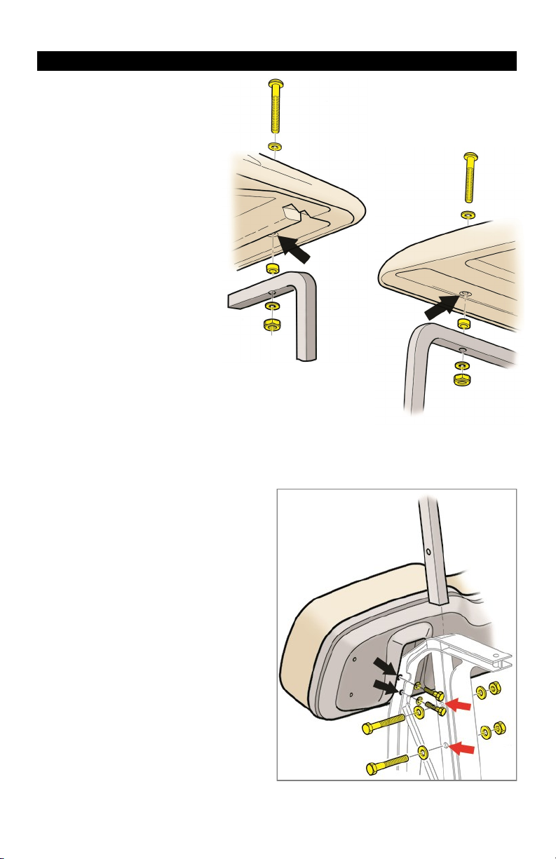
a (1 ea.) Front Seat Back Support, Driver Side
b (1 ea.) Front Seat Back Support, Passenger Side
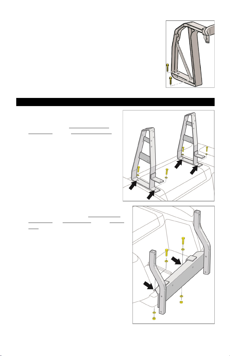
c (1 ea.) Vertical Support Bracket
d (1 ea.) Arm Rest, Passenger Side
e (1 ea.) Arm Rest, Driver Side
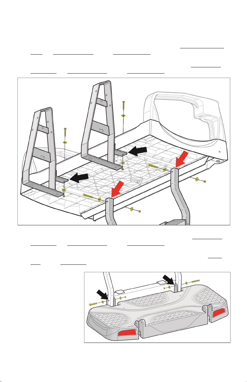
f (1 ea.) Platform
g (1 ea.) Footplate
h (1 ea.) Safety Grab Bar
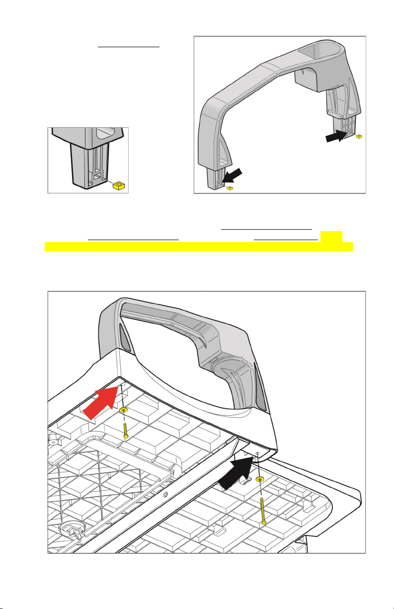
i (1 ea.) Seat Bottom Handle
j (1 ea.) Cushion Set (Not Shown)
k (1 ea.) Bag of Hardware (Contents on Next Page)

Page 2
Tools Needed For Installation
- Sockets and Open Ended Wrenches: 10mm, 12mm, 7/16”, 1/2”, 9/16”
- Phillips Screwdriver
- Rubber Mallet (Optional)
Contents of SEAT-511 Hardware Kit QTY
a3/8-16 x 1.5” Hex Head Bolts 4
b3/8” Flat Washers 4
cM8-1.25 x 55 Hex Head Bolts 4
dM8-1.25 x 45 Hex Head Bolts 2
eM8 Flat Washers 12
fM8-1.25 Nylock Nuts 6
gM6-1.0 x 70 Hex Head Bolts 2
hM6-1.0 x 45 Hex Head Bolts 2
iM6-1.0 x 35 Hex Head Bolts 2
jM6-1.0 x 30 Hex Head Bolts 6
kM6 Flat Washers 14
lM6 Lock Washers 4
mM6-1.0 Nylock Nuts 2
nM6-1.0 Square Nuts 4
o#10 x 3/4” Flat Head Sheet Metal Screws 2
p5/16” Ø, 2-5/8” Useable Length Clevis Pins 4
qHairpin Cotter Pins (3/32” wire Ø, 1-3/4” OAL) 4
rWeather Seal for Seat Bottom Cushion (not shown) 1

Page 3
Installation Preparation
1. Engage parking brake.
2. Turn key OFF.
3. Electric Carts Only: Place
Tow/Run Switch in Tow.
4. Remove top.
NOTE: If reinstalling the top,
keep the top attached to
the front struts and prop
up the rear of the top using
a broom handle or similar
tool. Retain hardware.
5. Remove the front seat back cushion
(black arrows). Retain hardware.
6. Remove rear struts (red arrows).
Retain hardware.
Front Strut (Driver Side)
Rear Strut (Driver Side)
(Driver Side)

Page 4
7. Remove both seat back supports and the bag attachment.
Driver side seat support shown.
Rear Seat Kit Installation
1. Install the new front seat back support
brackets where the original bracket was
installed using (4) 3/8-16 x 1.5” Hex
Head Bolts and (4) 3/8” Flat Washers.
NOTE: The driver and passenger side
brackets are different.
2. Loosely fasten the vertical support bracket to
the bagwell area using (2) 8mm x 45 Hex
Head Bolts, (4) Flat Washers and (2) Nylock
Nuts.

Page 5
3. Insert the (4) M6 Square Nuts into
the lower portions of the arm rests.
4. Place the arm rests with the square nuts inside of the seat platform as shown.
Fasten the arm rests to the platform using (2) M6 x 70 Hex Head Bolts (black
arrow), (2) M6 x 45 Hex Head Bolts (red arrow) and (4) M6 Flat Washers. Fully
tighten with hand tools but do not overtighten. Overtightening will cause damage.
NOTE: Driver side and passenger side arm rests are different. If oriented correctly,
the slots for the square nuts will face the outside of the platform.
(Driver Side Shown)

Page 6
5. Place the platform sub-assembly on top of the seat back support brackets and
vertical support bracket. A second installer will be helpful on this step.
6. Loosely fasten the platform to the seat back supports using (2) M6 x 30 Hex Head
Bolts, (4) M6 Flat Washers and (2) M6 Nylock Nuts (black arrows).
7. Loosely fasten the platform to the vertical support bracket using (2) M8 x 55 Hex
Head Bolts, (4) M8 Flat Washers and (2) M8 Nylock Nuts (red arrows).
8. Loosely fasten the footplate to the vertical support bracket using (2) M8 x 55 Hex
Head Bolts, (4) M8 Flat Washers and (2) M8 Nylock Nuts (upper mounting holes).
9. Secure the footplate to the bottom of the vertical support bracket using (2) Clevis
Pins and (2) Cotter Pins (not shown).
STORAGE NOTE:
To save space once
assembled, the clevis
and cotter pins can
be removed to fold
the footplate
assembly towards the
cart.
Bottom View of Platform

Page 7
10. Secure the safety grab bar to the footplate using (2) Clevis Pins and (2) Cotter Pins
on the upper mounting holes (black arrows) and (2) M6 x 35 Hex Head Bolts and
(2) M6 Flat Washers on the lower mounting holes (red arrows).
11. Install the front seat back to the new seat back brackets using the Original
Hardware.
12. Loosely fasten the rear seat back cushion to the rear seat back brackets using
(4) M6 x 30 Hex Head Bolts, (4) M6 Lock Washers and (4) M6 Flat Washers. Hand
tighten.
Bottom View of Footplate

13. If reinstalling the OE top and struts, install them to the seat back supports using the
Original Hardware.
NOTE: RHOX 88” Tops require TOP-0511 rear struts. Install TOP-0511 rear struts in
the same location as the OE struts.
14. Optional Weather Seal: Clean the surface of the platform indicated by the red
dashed line. Adhere the weather seal to the platform following the red dashed line.
15. Align the recessed areas on the seat bottom cushion with the locking tabs on the
seat platform (yellow). Slide the seat bottom onto the platform until it locks into
place on the locking tabs.
16. Secure the seat bottom using (1) seat bottom
handle and (2) No. 10 x 3/4” Flat Head Sheet
Metal Screws. Hand tighten.
17. Tighten any hardware left loose in this
installation.
This completes the installation of your
RHOX 500 Series Rear Seat Kit. Please enjoy safely!
Scan QR code or use the link below to
view the installation video.
https://vimeo.com/user39935056
Page 8
This manual suits for next models
1
Table of contents
Other RHOX Car Seat manuals
Popular Car Seat manuals by other brands

Mamas & Papas
Mamas & Papas Vito installation instructions

CYBEX gold
CYBEX gold SIRONA M2 i-Size user guide

Toyota
Toyota Auris 2006 installation instructions

BRITAX RÖMER
BRITAX RÖMER KID User instructions

VERTBAUDET
VERTBAUDET 1004234-0907 SA ISIZE 1/2/3 instruction manual

Britax
Britax BOULEVARD 65 CS manual