RIAN NDS3542A User manual

(MPEG-2 HD/MPEG-4 HD Encoding + DVB-T Modulating)
SW Version: 1.07
HW version: 0.1
Web NMS version: 1.03
4 HDMI to DVB-T Encoder Modulator
RIAN BV Bergstraat 25 5581 BL Waalre 040-2213656 [email protected]

Directory
CHAPTER 1 INTRODUCTION ...................................................................................................................1
1.1 PRODUCT OVERVIEW .........................................................................................................................1
1.2 KEY FEATURES ..................................................................................................................................1
1.3 SPECIFICATIONS.................................................................................................................................2
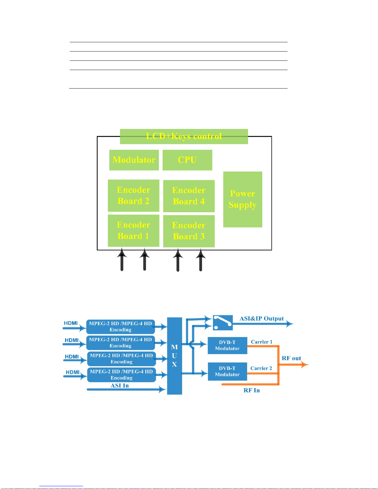
1.4 SCHEMATIC OVERVIEW ......................................................................................................................3
1.5 PRINCIPLE CHART..............................................................................................................................3
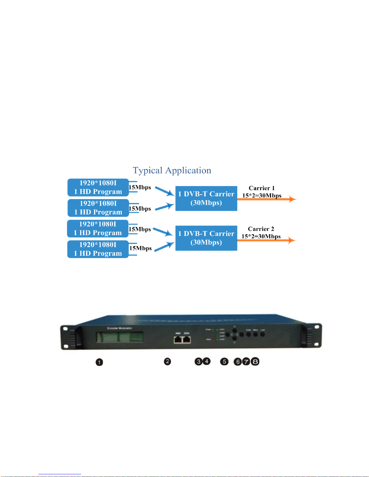
1.6TYPICALAPPLICATION OF DUAL CARRIER OUTPUTS............................................................................3
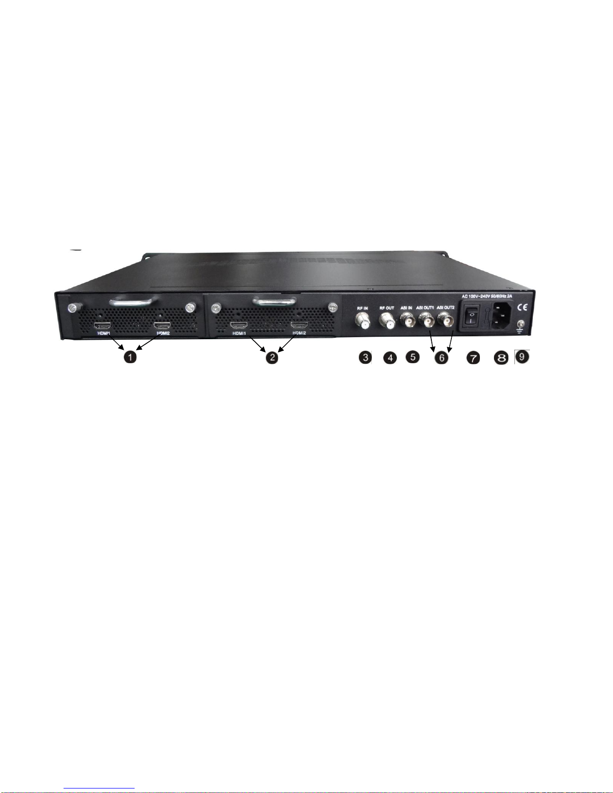
1.7APPEARANCE AND DESCRIPTION.........................................................................................................4
CHAPTER 2 INSTALLATION GUIDE...........................................................................................................6
2.1 GENERAL PRECAUTIONS ....................................................................................................................6
2.2 POWER PRECAUTIONS ........................................................................................................................6
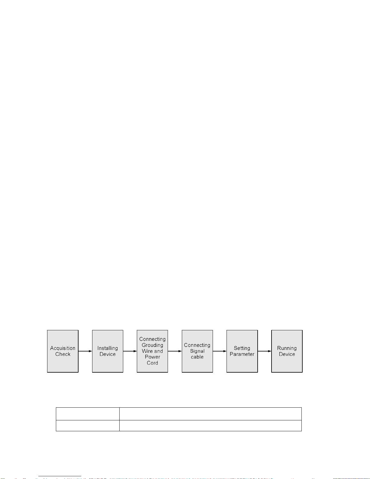
2.3 DEVICE’S INSTALLATION FLOW CHART ILLUSTRATED AS FOLLOWING ..................................................6
2.4 ENVIRONMENT REQUIREMENT ...........................................................................................................6
2.5 GROUNDING REQUIREMENT ...............................................................................................................7
CHAPTER 3 OPERATION..........................................................................................................................8
3.1 LCD MENUS .....................................................................................................................................8
3.2 INITIAL STATUS................................................................................................................................10
3.3 GENERAL SETTINGS FOR MAIN MENU ..............................................................................................11
CHAPTER 4 WEB NMS OPERATION.......................................................................................................19
4.1 LOGIN..............................................................................................................................................19
4.2 OPERATION......................................................................................................................................20
CHAPTER 5 TROUBLESHOOTING...........................................................................................................31

CHAPTER 6 APPLICATION.....................................................................................................................32
CHAPTER 7 PACKING LIST.....................................................................................................................34

Chapter 1 Introduction
1.1 Product Overview
1.2 Key Features
MPEG2 HD/MPEG4 HD video encoding
Up to 1920*1080@50P/60Psupported (MPEG4 HD)
Up to 1920*1080@50I/60I supported (MPEG2 HD)
4* HDMI in, 1*ASI in
Simultaneously encoding each channel more than 10Mbps
2* DVB-T RF out (2 carriers combined output)
IP(2 MPTS channels) out
LCN support (Logical Channel Number)
Excellent modulation quality MER≥42dB
All-in-one devices which integrate encoding (MPEG-2 HD, MPEG-4/AVC H.264) and
modulation (DVB-C, DVB-T, ISDB-T, or ATSC) to convert V/A signals into RF
output. It has equipped with 4 HDMI channels input and 1 ASI input and output with 2
ASI ports and 1 UDP IP port.
It adopts inner drawer-type structural design which greatly facilitates the change of
encoding modules (HDMI/CVBS/SDI/YPbPr/…) as needed.
The signals source could be from satellite receivers, closed-circuit television cameras,
Blue-ray players, and antenna etc. Its output signals are to be received by TVs, STB
and etc with corresponding standard.
With its various inputs available, our products are wildly used in public places such
as metro, market hall, theatre, hotels, resorts, and etc for advertising, monitoring,
training and educating in company, schools, campuses, hospital… It’s a good choice
to offer HD channels and more.

RF Frequency range 30Mhz~960Mhz
LCD display, Remote control and firmware
Web NMS management; Updates via web
Lowest cost per channel --- breakthrough price
1.3 Specifications
Encoding Section
Video
Encoding MPEG2 HD/MPEG4 HD
Input HDMI*4
Resolution 1920*1080_60P, 1920*1080_50P, (-for MPEG4/H.264)
1920*1080_60i, 1920*1080_50i,
1280*720_60p, 1280*720_50P
Audio
encoding MPEG1 Layer II, (MPEG2-AAC, MPEG4-AAC available )
Sample rate 48KHz
Bit rate 64kbps, 96kbps,128kbps, 192kbps, 256kbps, 320kbps
DVB-T Modulator Section
Standard EN300744
FFT mode 2K, 8K
Bandwidth 6M, 7M, 8M
Constellation QPSK, 16QAM, 64QAM
Guard Interval 1/4, 1/8, 1/16, 1/32
FEC 1/2, 2/3, 3/4, 5/6, 7/8
MER ≥42dB
RF frequency 30~960MHz, 1KHz step
RF out 2*RF COFDM DVB-T out (2 carrierscombined output);
Double output bandwidth
RF output level -30~ -10dbm (81~97 dbµV), 0.1db step
System
Local interface LCD + control buttons
Remote management Web NMS
output 2*ASI out (BNC type);
2*MPTS out (RJ45, 100M)
NMS interface RJ45, 100M
Language English
General

Power supply AC 100V~240V
Dimensions 482*400*44mm
Weight 4.5 kgs
Operationtemperature 0~45℃
1.4 Schematic Overview
1.5 Principle Chart
1.6 Typical Application of Dual Carrier Outputs
As we all know, to guarantee the picture quality of 1920x1080@50I/60I resolution HD

program, the video bit-rate may exceed 10Mbps, even up to 15Mbps. However, the
maximum possible bit-rate output for single DVB-T carrier is only around 30Mbps.
15Mbps x4 =60Mbps > 30Mbps.
It means the single DVB-T carrier simply can't carry the 4 channels 1080i HD
programs if the average bit-rate reaches 15Mbps.
That's why we design 2*DVB-T carrier modulation board which double the maximum
possible bit-rate bandwidth up to 60Mbps, which rightly makes it reliably carry 4
channels HD programs output simultaneously.
Below brief chart will help to more clearly illustrate the working principle.
1.7 Appearance and Description
Front Panel Illustration
①LCD window: LCD display
②NMS & DATA ports
③Power and Alarm Indicators

④Lock Indicators
⑤Up and down, left and right button
⑥Enter button: for confirm
⑦Menu button: for back step
⑧Lock button: press to lock set
Rear Panel Illustration
HDMI Module 1: HDMI input port 1&2
HDMI Module 2: HDMI input port 3&4
RF in port (for combiner use)
RF out port
ASI input port
ASI output ports
Switch
Power supply slot
Grounding

Chapter 2 Installation Guide
This section is to explain the cautions the users must know in some case that possible
injure may bring to users when it’s used or installed. For this reason, please read all
details here and make in mind before installing or using the product.
2.1 General Precautions
Must be operated and maintained free of dust or dirty.
The cover should be securely fastened, do not open the cover of the products when the
power is on.
After use, securely stow away all loose cables, external antenna, and others.
2.2 Power precautions
When you connect the power source, make sure if it may cause overload.
Avoid operating on a wet floor in the open. Make sure the extension cable is in good
condition
Make sure the power switch is off before you start to install the device
2.3 Device’s Installation Flow Chart Illustrated as following
2.4 Environment Requirement
Item Requirement
Machine Hall When user installs machine frame array in one machine hall,

Space the distance between 2 rows of machine frames should be
1.2~1.5m and the distance against wall should be no less than
0.8m.
Machine Hall Floor
Electric Isolation, Dust Free
Volume resistivity of ground anti-static material:
1X10⁷~1X10¹⁰,Grounding current limiting resistance: 1M
(Floor bearing should be greater than 450Kg/㎡)
Environment
Temperature 5~40℃(sustainable ),0~45℃(short time),
installing air-conditioning is recommended
Relative Humidity 20%~80% sustainable 10%~90% short time
Pressure 86~105KPa
Door & Window Installing rubber strip for sealing door-gaps and dual level
glasses for window
Wall It can be covered with wallpaper, or brightness less paint.
Fire Protection Fire alarm system and extinguisher
Power
Requiring device power, air-conditioning power and lighting
power are independent to each other. Device power requires
AC 110V±10%, 50/60Hz or AC 220V±10%, 50/60Hz. Please
carefully check before running.
2.5 Grounding Requirement
All function modules’ good grounding is the basis of reliability and stability of devices.
Also, they are the most important guarantee of lightning arresting and interference
rejection. Therefore, the system must follow this rule.
Grounding conductor must adopt copper conductor in order to reduce high frequency
impedance, and the grounding wire must be as thick and short as possible.
Users should make sure the 2 ends of grounding wire well electric conducted and be
antirust.
It is prohibited to use any other device as part of grounding electric circuit

The area of the conduction between grounding wire and device’s frame should be no
less than 25 mm2.
Chapter 3 Operation
3.1 LCD Menus
An overview of the LCD menus:


3.2 Initial Status
Switch on the device and after a few seconds’ initialization, it presents start-up pictures as
below:
DVB-T: indicate the modulation standard of this device
A: carrier output A; B: carrier output B
XXX.XX MHz indicates the current output frequency (range: 30~960MHz) of its
corresponding carrier output.
P1: Program 1; P2: Program 2; P3: Program 3; P4: Program 4
X.XX Mbps indicate the encoding bit rate of the corresponding program respectively.
Start up… Start OK… DVB-T A XXX.00MHz
P1:X.XXMbps P2: X.XXMbps

3.3 General Settings for Main Menu
Press “Lock” key on the front panel to enter the main menu. The LCD will display
the following pages where user can configure the parameters for the device:
User can press UP/DOWN buttons to specify menu item, and then press ENTER to
enter the submenus as below:
1) Alarm Status
The alarm indicator will turn on if there is no A/V signals inputting or outputting bit
rate overflows. User then can enter this menu to check the error type.
2) Encode Setting
Under this submenu, the LCD will show “2.1 Input 1”, “2.2 Input 2” and “2.3 ASI”.
Under submenus 2.1 or 2.2, user could set the video/audio encoding format and bit rate
of the program from the HDMI input.
1 Alarm Status
2 Encode Setting 3 Modulate Setting
4 IP Output Setting
5 Network Setting
6 Saving Config 7 Loading Config
8 Version
2.1 Input 1
2.2 Input 2 2.3 ASI
2.1 Input 1
2.1.1 Program 1
2.1.2 Program 2

“Video Format”: the HDMI MPEG2 HD encoding module supports both MPEG2
and H.264 formats. Move the triangle mark with LEFT/RIGHT keys to specify the
intended format and press ENTER to confirm.
“Video Bit Rate”: Move the underline with LEFT/RIGHT keys and modify the
value of frequency with UP/DOWN keys, and press ENTER key to save the
settings.
“Audio Format”: the encoding module supports MPEG2 audio format. This is a
read-only interface for checking.
“Select Program” is to select programs from the RF IN to output. Move the triangle
mark to specify the program and press ENTER to confirm.
Under submenu 2.3, user could parse the inputting programs and select the
programs to output.
Video Bit Rate
14.000 Mbps
Video Format
Video Bit Rate
MPEG2
64 Kbps
96 Kbps
Audio Format
Audio Bit Rate
MPEG2 H.264
►1 GXTV √
2 SZTV
X
Parse Program
Get 3 programs
Parse Program
Select Program A
Select Program B
2.3 ASI

“Parse Program” is for checking the quantity of input programs from the
corresponding Tuner input.
“Select Program A (or B)” is for selecting programs from the ASI IN to output through
Carrier A (or B). Move the triangle mark to specify the program and press
RIGHT/LEFT keys to shift the mark between “√” and “X”. (“√”: to output the
corresponding program; “X”: not to output the corresponding program)
3) Modulator Setting
When entering “Modulator Setting” submenu, user can find below different
parameters can be set and the LCD window would show as below:
As the NDS3542A is with dual carrier outputs, “3.1” and “3.2” represent the
“Carrier A” and “Carrier B” respectively. User can enter “3.1” or “3.2” to set the
corresponding modulating parameters. Submenus are as below:
Bandwidth
There are three possible options provided for selecting bandwidth: 6M, 7M, and 8M.
When the display shows them, user just need swift LEFT and RIGHT key to choose
and repressing ENTER to confirm.
3.1 Bandwidth
3.2 Constellations
3.5 Code Rate
3.6 RF Frequency
3.3 Transmission Mode
3.4 Guard Interval
3.7 RF Out Level
3.8 RF On
Bandwidth
6M 7M 8M
3.1 Output A
3.2 Output B 3.3 ASI Output

Constellation
There are three different constellations QPSK, 16QAM and 64QAM shown on the LCD
window. When entering Constellation, user can apply the same setting method as
mentioned above to select and confirm one mode.
Transmission Mode
When user enters Transmission Mode, the LCD would show the current working mode.
User can move LEFT/RIGHT keys to select and press ENTER key to confirm. 2K and
8K are the options:
2K: When the device works as current mode, the number of current carrier is 2048
8K: When the device works as current mode, the number of current carrier is 8192
Guard Interval
In communications, guard intervals are used to ensure that distant transmissions do
not interfere with each other. These transmissions may belong to different users (as in
TDMA) or same user (as in OFDM). The purpose of the guard interval is to
introduce immunity to propagation delays, echoes and reflections, to which digital
data is normally very sensitive. There are four possible options provided to be
selected. They are 1/4, 1/8, 1/16, 1/32. User can shift the LEFT/RIGHT keys to select
and press ENTER to confirm.
Code Rate
The code rate includes 1/2, 2/3, 3/4, 5/6, and 7/8. After entering this submenu, the
Guard Interval
1/8 1/16 1/32
Transmission Mode
2K 8K
Constellation
QPSK 16QAM 64QAM

LCD display would show them, users just need press LEFT and RIGHT buttons to
choose and press ENTER button to confirm.
RFFrequency
The RF output frequency range is from 30 to 960MHz with 1K stepping. After entering
the RF frequency setting submenu, users the can press LEFT, RIGHT, UP, and DOWN
buttons to adjust the frequency and confirm by press ENTER button.
RFOut Level
The RF attenuation range is -30~-10dbm (81~97dbµV) with 0.1db step. After entering
this setting submenu, user can shift UP/DOWN/LEFT/RIGHT key to set the output
level and press ENTER to confirm.
RFOn
This interface is to decide whether to enable the RF (carrier A) output or not.
OFF: to disable programs to output through carrier A.
ON: to enable programs to output through carrier A.
NOTE: The setting principle of “3.2” is the same with “3.1” explained above.
ASI Output
If the encoder & modulator is with dual-carrier output: Output A and Output B.
Code Rate
1/2 2/3 3/4 5/6
RF Frequency
750.000 MHz
RF Out Level
-10.0 dbm
RF On Off On

Output A: the ASI output programs are same as carrier output A.
Output B: the ASI output programs are same as carrier output B.
4) IPOutput Setting
The NDS3542A encoder & modulator is with two dual-carrier output (Output A and
Output B), 4.1 and 4.2 are for the settings of the two carrier output respectively.
Submenus go as 4.1.1-4.1.6.
User can enter 4.1.1 to decide whether to turn the IP port on or off, and enter to the
rest menu items to set the corresponding parameters.
5) Network setting
After enter Network Setting, there are three submenus shows as the following LCD
displays.
User can press “UP/DOWN” to choose this item and “ENTER” & “LEFT/RIGHT” to
set the parameters.
5.5 Reset Password
5.6 Web Manage Port
5.3 Gateway
5.4 MAC Address
5.1 IP Address
5.2 Subnet Mask
4.1.1 IP Output
4.1.2 Service IP 4.1.3 Output IP
4.1.4 Subnet Mask
4.1.5 Gateway
4.
1.6 Port
ASI Output
Output A Output B
4.1 IP Output A
4.2 IP Output B

NOTE: The MAC address is according to the factory setting, and it is unique. It
can only be modified through special software.
6) Saving Configuration
Users can enter Saving Configuration submenu for saving settings. Choose yes and
press ENTER to confirm.
7) Loading Configuration
At this menu, user can press UP/DWON key to select and repress ENTER to confirm.
User can restore the device into the last saved configuration by choosing “7.1” and
restore the device into factory configuration by choosing “7.2” the display will show
as below:
8) Version
User can check the software version and hardware version of this equipment under
IP Address
192.168.000.136 Subnet Mask
255.255.255.000
Gateway
192.168.000.001 MAC Address
ffffffffffffffffffffff
Reset Password?
Yes NO
Save Configuration?
Yes
No Saving Config…
Load Saved CFG?
Yes
No Loading Config…
7.1 Load Saved CFG
7.2 Load Default
Web Manage Port
00080
Table of contents