RIB NOVA Wi-Fi User manual

NOVA Wi-Fi
ITALIANO pag. 02 / FRANÇAIS pag. 08 / ENGLISH page 14 / DEUTSCH pag. 20 / ESPAÑOL pag. 26
FOTOCELLULE SENZA FILI
⚠
NON POSIZIONARE LA SCHEDA DI GESTIONE MASTER Wi-Fi DIETRO A MURI, PANNELLI METALLICI O ALTRI TIPI DI OSTACOLI CHE POSSANO IMPEDIRE LA
COMUNICAZIONE RADIO CON NOVA Wi-Fi
PHOTOCELLULES SANS FIL
⚠
NE PAS POSITIONNEZ LA FICHE DE GESTION MASTER Wi-Fi DERRIÈRE DES MURS, PANNEAUX MÉTALLIQUES, OU AUTRES TYPES D’OBSTACLES QUI
POURRAIENT COMPROMETTRE LA TRANSMISSION RADIO AVEC NOVA Wi-Fi.
PHOTOCELLS WITHOUT WIRES
⚠
DO NOT INSTALL MASTER Wi-Fi RECEIVER CARD BEHIND WALLS, METAL FRAMES OR PANELS, OR OTHER KIND OF OBSTACLES THAT COULD PREVENT THE
PROPER RADIO COMMUNICATION WITH NOVA Wi-Fi.
FOTOZELLEN OHNE KABEL
⚠
NICHT INSTALLIEREN MASTER Wi-Fi KARTE HINTER MAUERN, METALLPLATTEN ODER ANDERE ARTEN VON HINDERNISSEN, DIE DEN FUNKVERKEHR MIT NOVA
Wi-Fi BEEINTRÄCHTIGEN KÖNNEN.
FOTOCÉLULAS SIN CABLES
⚠
NO INSTALAR LA FICHA DE GESTION MASTER Wi-Fi EN UN LUGAR DETRÁS DE LAS PAREDES, DE PANELES DE METAL O DE OTRO TIPO DE OBSTÁCULOS QUE
PUEDAN IMPEDIR LA COMUNICACIÓN POR RADIO CON NOVA Wi-Fi
I
F
G
B
E
S
D
code ACG8037
Batterie alcaline AA non incluse
Piles alcalines AA non incluses
AA Alkaline batteries not included
AA Akaline-Batterien nicht beiliegend
Baterías alcalinas AA no incluidas
MASTER Wi-Fi
🚫
NO - NEIN !
MASTER Wi-Fi
✅
SI - OUI - YES - JA !
✅
SI - OUI - YES - JA !
MASTER Wi-Fi
MASTER Wi-Fi
🚫
NO - NEIN !

2
I
SETTAGGI E COLLEGAMENTI TRASMETTITORE
J6 Morsetti per collegamento del contatto pulito della costa meccanica o resistiva
(N.C. o N.O.)
SWTX Microinterruttori di abbinamento e identificazione
JP3 Ponticello abilitazione/esclusione costa (di serie ponticello non inserito per costa
non collegata. Chiudere il ponticello se si collega una costa)
JP4 Ponticello selezione contatto costa N.O./N.C. (impostazione di fabbrica N.C.)
JP5 Ponticello selezione range di portata 13/25 m (impostazione di fabbrica 25 M)
BAT Batterie alcaline 2 x AA 1,5V
DLTX Led verde per verifica funzionamento
SETTAGGI E COLLEGAMENTI RICEVITORE
J7 Morsetti per collegamento del contatto pulito della costa meccanica o
resistiva (N.C. o N.O.)
SWRX Microinterruttori di abbinamento e identificazione
S3 PROG. TX Pulsante per memorizzazione e allineamento
JP6 Ponticello abilitazione/esclusione costa (di serie ponticello non inserito
per costa non collegata. Chiudere il ponticello se si collega una costa)
JP7 Ponticello a filo selezione funzionamento come fotocellula o costa
(impostazione di fabbrica CHIUSO)
JP8 Ponticello selezione contatto costa N.O./N.C. (impostazione di fabbrica
N.C.)
BAT Batterie alcaline 2 x AA 1,5V
DLRX Led rosso per segnalare la corretta alimentazione e l’allineamento del
segnale infrarosso
RIFERIMENTI NORMATIVI PER PORTE E CANCELLI AUTOMATICI
L’installatore deve assicurarsi che l’installazione delle fotocellule NOVA Wi-Fi sia fatta solo in
presenza di una ulteriore protezione principale come specificato nella norma EN 12453 al punto
5.1.3 (requisiti generali di protezione).
RIB NON PUÓ CONSIDERARSI RESPONSABILE PER EVENTUALI DANNI CAUSATI DA UN USO
IMPROPRIO, ERRONEO O IRRAGIONEVOLE.
Restrizioni d’uso: Le fotocellule NOVA Wi-Fi non possono essere utilizzate su apparecchiature
escluse dall’applicazione della EN 12978, quali:
- apparati di protezione per installazione su porte destinate ad un uso differente rispetto a
quello sulle porte di accessi pedonali e veicolari coperti dalla norma e il cui principale uso è
quello di dare accesso sicuro in luoghi industriali, commerciali, pubblici o residenziali. Alcuni
esempi di esclusioni possono essere: chiuse e paratie; porte di ascensori; porte di veicoli;
porte principalmente usate per la custodia di animali; tende in tessuto per teatro; barriere
ferroviarie; barriere utilizzate solo per veicoli.
- dispositivi usati solo per il controllo normale e per l’arresto, incluso l’arresto di emergenza,
di porte motorizzate.
- apparati di sicurezza o dispositivi di sicurezza per l’uso su macchine diverse dalle porte.
⚠
Eventuali modifiche del prodotto o della configurazione dell’apparato non possono essere
eseguite senza consultare il fabbricante o il suo rappresentante autorizzato.
L’installatore del dispositivo di sicurezza deve fornire all’utilizzatore finale quanto segue:
- i dispositivi di sicurezza devono essere fatti conoscere a tutte le persone appropriate.
- le aree che danno accesso ai dispositivi devono essere tenute libere da ostacoli;
- i requisiti per la pulizia per evitare eventuali accumuli pericolosi di materiale;
- possibili dettagli per una procedura di riavvio da eseguire dopo una fermata di emergenza o
accidentale causata dal sistema di controllo.
La modifica del progetto o della configurazione dell’apparato senza la consultazione del
fabbricante o del suo rappresentante autorizzato può creare situazioni pericolose.
POSSIBILITÁ DI IMPIEGO
Le fotocellule NOVA Wi-Fi comunicano costantemente ed esclusivamente con la scheda
MASTER Wi-Fi e soddisfano completamente i requisiti di una sicurezza attiva su tutti i tipi di
aperture automatiche.
⚠
Se viene tolta l’alimentazione del MASTER Wi-Fi per un periodo di tempo prolungato le
coste TOUCH Wi-Fi e le fotocellule NOVA Wi-Fi esauriranno più velocemente del normale
la carica delle loro batterie. Tenere i MASTER Wi-Fi sempre correttamente alimentati per
garantire la durata di 3 anni delle batterie come dichiarata da RIB.
Se per esempio viene tolta la tensione al cancello tutte le notti, fotocellule e coste “cercano”
ripetutamente il segnale dal MASTER Wi-Fi senza trovarlo e quindi la durata delle batterie di
questi accessori si riduce a meno di un anno.
⚠
OGNI VOLTA CHE SI ESEGUE UNA NUOVA CONFIGURAZIONE TRAMITE PONTICELLO È NECESSARIO TOGLIERE E RIDARE ALIMENTAZIONE SIA AL TRASMETTITORE CHE AL RICEVITORE.
SCHEMA CON POSIZIONI STANDARD DEI PONTICELLISCHEMA CON POSIZIONI STANDARD DEI PONTICELLI
JP7
JP6
JP8
S3
BAT
SWRX
J7
DLRX
JP4
JP3
BAT
JP5
DLTX
SWTX
J6

3
⚠
Prima di posizionare o incollare la dima
di foratura (cod. CVA1940) controllare
che la superficie di contatto sia pulita.
- Fissare le basi plastiche CPL1312 sui
pilastri o sulle colonnine ad un’altezza
di circa 40÷60 cm dal suolo e ad una
distanza max di 10 cm dalla zona di
convogliamento o schiacciamento
o subito dopo l’ingombro dato da
un’eventuale costa.
- Terminare le regolazioni montare lo
schermo protettivo CPL1311.
- Installare il ricevitore NOVA Wi-Fi al
massimo a 20 metri di distanza dalla
scheda MASTER Wi-Fi per consentire il
corretto funzionamento radio e in ombra
o in una posizione in cui il sole non possa
battere orizzontalmente per consentire
il corretto funzionamento del segnale
infrarosso.
- In ogni caso si consiglia di posizionare le
fotocellule alla stessa altezza e allineate
tra loro.
- Per il corretto posizionamento delle
fotocellule fare riferimento al manuale di
installazione dell’operatore o comunque
alla norma EN12453.
I
MONTAGGIO
LE FOTOCELLULE NOVA Wi-Fi SONO ACCESE SOLO DURANTE L’AZIONAMENTO DELLA PORTA.
GRAZIE ALLA FUNZIONE SLEEP MODE, A PORTA FERMA LE FOTOCELLULE SONO SPENTE
CONSENTENDO UN RISPARMIO ENERGETICO DELLE BATTERIE.
Sono prodotte nella versione da parete, da fissare su colonne in ferro o di altro materiale liscio,
o su COLONNINE DI SUPPORTO DEDICATE cod. ACG8039.
CPL1311 CPL1312
BC08037R
BC08037T CVA1940
Le fotocellule NOVA Wi-Fi possono essere installate vicinissime tra di loro grazie alla funzione
di SINCRONISMO.
Il SINCRONISMO è garantito per 2 coppie di fotocellule con DIP 1 ON (1acoppia) e DIP 2 ON (2a
coppia).
Eventuali altre 2 coppie di fotocellule possono essere installate, ma invertite nella loro
trasmissione/ricezione rispetto alle 2 coppie precedenti.
Devono essere settate con DIP 3 ON (3acoppia) e DIP 4 ON (4acoppia).
⚠
POSIZIONARE IL RICEVITORE DELLA FOTOCELLULA IN VISTA DELLA SCHEDA MASTER Wi-Fi. TRA MASTER Wi-Fi E RICEVITORE NOVA Wi-Fi NON DEVONO ESSERCI OSTACOLI IN METALLO O IN CEMENTO.
Se non è possibile posizionare il Ricevitore NOVA Wi-Fi in vista della scheda MASTER Wi-Fi per la presenza di ostacoli, installare un’antenna 868 MHz (cod. ACG5451) a MASTER Wi-Fi in modo
da garantire la buona qualità delle trasmissioni radio.
Questi accorgimenti evitano che le batterie del Ricevitore NOVA Wi-Fi si scarichino velocemente.
RX PHOT 3 TX PHOT 3
TX PHOT 1 RX PHOT 1
TX PHOT 2 RX PHOT 2
RX PHOT 4 TX PHOT 4

4
⚠
È possibile collegare sia al ricevitore che al trasmettitore delle coste meccaniche o
resistive come riferito nel paragrafo “COLLEGAMENTO DI COSTE MECCANICHE O RESISTIVE”.
PORTATA
È possibile decidere la portata delle fotocellule posizionando un jumper sul/sui trasmettitore/i.
Ponticello JP5 con portata regolata a 13 m
JP5
Ponticello JP5 con portata regolata a 25 m (impostazione di fabbrica)
JP5
Con JP5 con portata regolata a 13 m le batterie possono durare più di 4 anni.
Con JP5 con portata regolata a 25 m le batterie durano 3 anni.
Queste durate sono previste con 20 manovre al giorno per tutto l’anno.
Dopo aver fissato le basi plastiche delle fotocellule NOVA Wi-Fi, inserire le schede elettroniche
nelle apposite sedi predisposte sulle basi e quindi fissarle con le viti in dotazione.
COLLEGAMENTO BATTERIE
- Inserire le due batterie alcaline tipo AA da 1,5V facendo attenzione alle polarità (si veda
immagine a lato).
- Nel momento dell’inserimento delle batterie sul trasmettitore
TX NOVA Wi-Fi il led verde si accende per 10 s segnalando
il corretto funzionamento. In seguito il led si spegne per
non consumare inutilmente l’energia delle batterie, ma la
trasmissione del segnale infrarosso è attiva.
- Nel momento dell’inserimento delle batterie sul ricevitore
RX NOVA Wi-Fi il led rosso si accende per 3 s segnalando il
corretto funzionamento.
- Se il led rosso rimane acceso le fotocellule sono già
correttamente allineate.
- Se il led rosso si spegne, eseguire l’allineamento del segnale
infrarosso come descritto nel paragrafo successivo.
ALLINEAMENTO E SINCRONIZZAZIONE DEL SEGNALE INFRAROSSO
- Le fotocellule NOVA Wi-Fi vengono confezionate con allineamento centrale, tuttavia in caso
di necessità è possibile eseguire una regolazione dei gruppi ottici del trasmettitore e del
ricevitore (+90°/-90° in orizzontale e +5°/-5° in verticale).
- Premere il tasto S3 PROG. TX presente sul Ricevitore NOVA Wi-Fi per attivarlo per 3 minuti
(tempo necessario ad eseguire l’allineamento fra trasmettitore e ricevitore).
⚠
Trascorsi 3 minuti il led rosso si spegne per non consumare inutilmente l’energia
delle batterie, tuttavia è possibile rinnovare il tempo di altri 3 minuti semplicemente
ripremendo il tasto S3 PROG. TX.
- Ad allineamento eseguito il led rosso presente sul Ricevitore NOVA Wi-Fi si deve accendere
fisso indicando la corretta ricezione del segnale infrarosso ricevuto dal Trasmettitore
NOVA Wi-Fi. Se il led rosso lampeggia, ciò significa che il segnale risulta debole e quindi
l’allineamento è da migliorare fino a quando il led rosso resta acceso fisso.
- Se il trasmettitore ed il ricevitore sono montati ad una distanza inferiore a 13 metri,
consigliamo di posizionare il ponticello JP5 come indicato nel paragrafo “PORTATA” in questo
modo si ha un minor consumo delle batterie con conseguente allungamento della vita delle
stesse.
- Montare lo schermo protettivo.
IDENTIFICAZIONE
Ogni coppia di fotocellule NOVA Wi-Fi viene fornita con i microinterruttori in posizione OFF per
evitare il consumo delle batterie quando non viene utilizzata (se collegate).
Ogni coppia di fotocellule NOVA Wi-Fi deve essere OBBLIGATORIAMENTE univocamente
identificata mettendo su ON un solo diverso DIP
dei 6 presenti sulla scheda. Esempio: Impostare DIP 1 ON su MASTER Wi-Fi, DIP 1 ON su ricevitore
NOVA Wi-Fi e DIP 1 ON su trasmettitore NOVA Wi-Fi.
IDENTIFICARE I CONTENITORI DELLE FOTOCELLULE NOVA Wi-Fi APPLICANDO L’ADESIVO IN
DOTAZIONE ALL’ESTERNO DI OGNI CONTENITORE.
L’IDENTIFICAZIONE SERVE PERCHE’ POSSA ESSERE VELOCEMENTE IDENTIFICATA LA FOTOCELLULA
QUANDO LE SUE BATTERIE SONO QUASI SCARICHE.
MEMORIZZAZIONE
Dopo avere eseguito l’allineamento e l’identificazione delle fotocellule NOVA Wi-Fi, settare i
microinterruttori sulla scheda MASTER Wi-Fi per abilitare le fotocellule da memorizzare (questa
operazione può essere eseguita anche dopo la procedura di memorizzazione).
Per eseguire la memorizzazione seguire la seguente procedura:
- Premere il tasto PROG RX che si trova sulla scheda MASTER Wi-Fi=> il LED EDGE PHOT 1 rimarrà
acceso rosso lampeggiante per 1 minuto (tempo utile per eseguire la memorizzazione).
12/24V ac/dc
PROG RX LED EDGE PHOT
- Premere il tasto PROG TX sul ricevitore con DIP 1 su ON => sul MASTER Wi-Fi il LED EDGE PHOT 1
da rosso lampeggiante diventa verde e un tono di buzzer segnala la corretta memorizzazione
della fotocellula. Contemporaneamente si accende lampeggiante rosso il LED EDGE PHOT 2
per 1 minuto (tempo utile per eseguire la memorizzazione).
Se non vengono memorizzate altre fotocellule lasciare trascorrere un minuto oppure premere
il tasto PROG. RX per 4 volte per terminare la procedura di memorizzazione (il LED EDGE PHOT
2si spegnerà) => tutti i LED EDGE PHOT devono risultare spenti durante il funzionamento
normale.
PER MEMORIZZARE ALTRE FOTOCELLULE NOVA Wi-Fi:
- Premere il tasto PROG. TX sulla fotocellula con DIP 2 su ON => sul MASTER Wi-Fi il LED
EDGE PHOT 2 da rosso lampeggiante diventa verde e un tono di buzzer segnala la corretta
memorizzazione della fotocellula.
- Eseguire la stessa procedura per eventuali altre fotocellule (fino ad un massimo di 4).
⚠
a fine procedura di memorizzazione e dopo aver abilitato i microinterruttori riferiti alle
sicurezze memorizzate sul MASTER Wi-Fi, eseguire una scansione dei LED EDGE PHOT
premendo per 6 volte il tasto PROG. RX.
VERIFICA DEL CORRETTO FUNZIONAMENTO
Terminata la procedura di memorizzazione, verificare il corretto funzionamento tra Fotocellule
NOVA Wi-Fi e MASTER Wi-Fi nel seguente modo:
- Premere il tasto S3 PROG. TX presente su un RX NOVA Wi-Fi per attivarne il led rosso per 3
minuti.
- Verificare che interponendo un ostacolo il led rosso si spenga e che
contemporaneamente sulla MASTER Wi-Fi il corrispondente LED EDGE PHOT si accenda di
colore verde per la durata dell’interposizione.
Anche il led DL3 del MASTER Wi-Fi si deve spegnere per segnalare l’avvenuto corretto scambio
del contatto dedicato all’ingresso PHOT sulla centralina comando motore.
Ripetere la verifica sulle altre fotocellule NOVA Wi-Fi installate.
Eseguirepoiunaverificafunzionaledi tuttelefotocelluleinstallateattivandola movimentazione
dell’automazione e controllando che interponendo un ostacolo l’automazione fermi/inverta se
in chiusura, oppure fermi/continui ad aprire se in apertura.
ANTENNA
L’antenna radio è già collegata su tutti i ricevitori NOVA Wi-Fi. NON TOCCATELA !!!
VERIFICA DELLA SEGNALAZIONE DI ALLARME
Verificare che staccando una batteria dal ricevitore fotocellula con ad esempio DIP 3 su ON, ed
eseguendo un comando di apertura della porta, su MASTER Wi-Fi il LED EDGE PHOT 3 lampeggi
verde/rosso, mentre i led DL2 e DL3 si spengono, e che il buzzer emetta un suono alternato
per 1 minuto.
Ripetere la verifica su eventuali altre fotocellule installate.
⚠
se togliendo la batteria dal ricevitore fotocellula ed eseguendo un comando di apertura
della porta il buzzer su MASTER Wi-Fi non suona, il DIP 3 su MASTER Wi-Fi si trova su OFF
(consenso non abilitato). Posizionarlo su ON.
STATO DI ATTENZIONE (avviso di sostituzione batterie)
Lo stato di attenzione (WARNING) avverte l’utilizzatore dell’imminente necessità di sostituire
le batterie.
I

5
Quando le batterie quasi scariche raggiungono i 2,3V, la fotocellula ricevitore segnala via radio
a MASTER Wi-Fi lo stato di batteria quasi scarica e attiva il BUZZER di MASTER Wi-Fi con un tono
ogni 3 s per 1 minuto.
Lo stato di attenzione si rinnova per 1 minuto a fronte di un comando della porta.
Il LED EDGE PHOT riferito alla fotocellula con le batterie quasi scariche, si accende fisso rosso.
Durante queste segnalazioni il sistema è ancora funzionante, ma è opportuno sostituire al più
presto le batterie evitando il blocco della porta che avviene al raggiungimento dei 2,0 V.
STATO DI ALLARME
Lo stato di allarme si attiva con batterie completamente scariche (2,0 V) o con guasto della
fotocellula.
Su MASTER Wi-Fi i led DL2 e DL3 si spengono bloccando l’automazione in quanto non è garantita
la funzionalità di una delle fotocellule installate.
Su MASTER Wi-Fi (fw 01_04_13) il led riferito alla fotocellula con batterie scariche o guasta,
lampeggia rosso ed il buzzer emette un tono ogni 3 s per 1 minuto richiamando l’attenzione
dell’utilizzatore che dovrà sostituire le batterie o riparare la fotocellula.
Lo stato di allarme si rinnova per 1 minuto a fronte di un comando della porta.
PER ESCLUDERE LA SINGOLA FOTOCELLULA LEGGERE IL MANUALE DEL MASTER Wi-Fi.
SOSTITUZIONE DELLE BATTERIE
La durata delle batterie delle NOVA Wi-Fi è di circa 3 anni.
- Identificare quale fotocellula ha le batterie scariche guardando i led EDGE-PHOT sulla MASTER
Wi-Fi.
Il LED EDGE PHOT della sicurezza registrata sul MASTER:
- lampeggia rosso/verde (se in allarme)
- su MASTER Wi-Fi fw 01_04_13 lampeggia rosso (se in allarme)
- acceso rosso fisso (se in attenzione)
- acceso verde fisso (se batteria trasmettitore NOVA Wi-Fi scarica)
- Ricercare sul contenitore delle fotocellule l’adesivo con il numero corrispondente.
- Sostituire le batterie sia sul trasmettitore che sul ricevitore facendo attenzione al rispetto
delle polarità.
- Premere il tastino PROG TX della fotocellula ricevitore per riattivare il funzionamento di
MASTER Wi-Fi. Il buzzer a bordo della MASTER Wi-Fi se attivo si spegne e i led DL2- DL3 (se in
allarme) si accendono e il LED EDGE PHOT riferito alla fotocellula a cui sono state sostituite
le batterie si spegne.
L’automazione è pronta a ripartire in tutta sicurezza.
⚠
Vi ricordiamo che le batterie vanno smaltite secondo le Norme vigenti. In caso di
rottamazione delle fotocellule vi ricordiamo di togliere le batterie e di smaltirle secondo
le Norme vigenti.
AGGIUNTA DI ALTRE FOTOCELLULE NOVA Wi-Fi (MAX 6 TOTALI)
Se dopo l’installazione si decidono di applicare altre fotocellule per aumentare lo stato di
sicurezza della porta, si consiglia di:
- Togliere tensione alla porta.
- Fissare la coppia di fotocellule aggiuntiva nella posizione desiderata.
- Eseguire la programmazione posizionando un DIP su ON, diverso da quello delle altre
fotocellule o sicurezze installate e identificarla con l’adesivo numerato corrispondente (vedi
paragrafo “Identificazione”).
- Abilitare sulla scheda MASTER Wi-Fi il DIP relativo alla fotocellula appena aggiunta.
- Dare tensione alla porta.
Eseguire le procedure di memorizzazione e verifica come indicato precedentemente.
PROCEDURA DI CANCELLAZIONE DELLA SINGOLA SICUREZZA (FOTOCELLULA O
COSTA) IN CASO DI GUASTO O SOSTITUZIONE
Per cancellare una singola sicurezza memorizzata su MASTER Wi-Fi, procedere nel seguente
modo:
- Premere una o più volte il tasto PROG. RX per selezionare il LED EDGE PHOT che lampeggia
verde, corrispondente alla sicurezza da eliminare.
- Selezionata la sicurezza, premere e mantenere premuto il tasto PROG. RX per 10 s.
- Al termine dei 10 s il LED EDGE PHOT lampeggia per 6 volte rosso/verde, segnalando l’avvenuta
cancellazione.
⚠
Posizionare su OFF il DIP relativo alla sicurezza eliminata, poi eseguire una scansione dei
led premendo per 6 volte il tasto PROG. RX.
⚠
Togliere le batterie alla sicurezza eliminata.
COLLEGAMENTO DEL CONTATTO PULITO DI COSTE MECCANICHE O RESISTIVE
ALLE FOTOCELLULE NOVA Wi-Fi
È possibile collegare ai trasmettitori e ai ricevitori NOVA Wi-Fi delle coste meccaniche o
resistive.
Per i collegamenti delle coste al trasmettitore o al ricevitore della fotocellula NOVA Wi-Fi,
utilizzare un cavo da 2 x 0,5 mm2con diametro esterno massimo di 5 mm.
In caso si utilizzi un cavo di diametro inferiore, è opportuno verificare che il passacavo
garantisca la NON infiltrazione di acqua, pertanto per mantenere il grado di protezione IP44
chiudere ermeticamente con silicone le eventuali aperture intorno al cavo.
LA FUNZIONALITÁ DELLA COSTA CAMBIA IN BASE A DOVE È COLLEGATA, PERTANTO FARE
ATTENZIONE A QUANTO SEGUE:
La costa collegata al RICEVITORE NOVA Wi-Fi:
- se attivata mentre il cancello sta CHIUDENDO => INVERTE IL MOVIMENTO IN APERTURA;
- se attivata mentre il cancello sta APRENDO => INVERTE IL MOVIMENTO IN CHIUSURA.
IL SUO FUNZIONAMENTO È QUINDI QUELLO INDICATO PER UNA COSTA.
La costa collegata al TRASMETTITORE NOVA Wi-Fi:
- se attivata mentre il cancello sta CHIUDENDO => INVERTE IL MOVIMENTO IN APERTURA;
- se attivata mentre il cancello sta APRENDO => FERMA E POI LASCIA CONTINUARE L’APERTURA.
IL SUO FUNZIONAMENTO È QUINDI COME QUELLO DI UNA FOTOCELLULA.
PER COSTE MECCANICHE TOUCH (cod. ACG3015) CON CONTATTO N.C.
- Collegare in serie al contatto N.C. della costa una resistenza da 8,2 KΩ (senza tale resistenza il
sistema non funziona ed entra in allarme - vedere tabella “IN CASO DI DIFFICOLTÁ)
- Collegare ai morsetti J6 per il trasmettitore o J7 per il ricevitore il contatto N.C. della costa.
- Posizionare sul ricevitore il ponticello JP6 nella seguente posizione per abilitare la costa:
JP6
- Posizionare sul ricevitore il ponticello JP8 nella seguente posizione per gestire il contatto
N.C.: JP8
- Posizionare sul trasmettitore il ponticello JP3 nella seguente posizione per abilitare la costa:
JP3
- Posizionare sul trasmettitore il ponticello JP4 nella seguente posizione per gestire il contatto
N.C.: JP4
PER COSTE RESISTIVE CON CONTATTO N.O.
- Collegare in parallelo al contatto N.O. della costa una resistenza da 8,2 KΩ (senza tale
resistenza il sistema non funziona ed entra in allarme - vedere tabella “IN CASO DI DIFFICOLTÁ).
- Collegare ai morsetti J6 per il trasmettitore o J7 per il ricevitore il contatto N.O. della costa.
- Posizionare sul ricevitore il ponticello JP6 nella seguente posizione per abilitare la costa:
JP6
- Posizionare sul ricevitore il ponticello JP8 nella seguente posizione per gestire il contatto
N.O.: JP8
- Posizionare sul trasmettitore il ponticello JP3 nella seguente posizione per abilitare la costa:
JP3
- Posizionare sul trasmettitore il ponticello JP4 nella seguente posizione per gestire il contatto
N.O.: JP4
I

6
FUNZIONE SPECIALE
CON IL RICEVITORE NOVA Wi-Fi È POSSIBILE, TRAMITE IL PONTICELLO JP7, FARE FUNZIONARE LA
FOTOCELLULA COME UNA COSTA.
Eseguire la seguente procedura:
- Togliere le batterie sul ricevitore NOVA Wi-Fi.
- Tagliare il ponticello JP7.
- Rimettere le batterie.
- Eseguire la memorizzazione su MASTER Wi-Fi
- Selafotocellulaègiàstataprecedentementememorizzata,eseguireunasingolacancellazione
della posizione precedentemente memorizzata, e quindi eseguire la memorizzazione con la
nuova configurazione.
A QUESTO PUNTO LE FOTOCELLULE SE INTERCETTATE AGISCONO COME COSTA SIA IN APERTURA
CHE IN CHIUSURA.
Questa funzione serve per proteggere le zone non interessate al transito veicolare, ma solo
pedonale (area in cui scorre la parte mobile del cancello mentre si sta aprendo o area tra
le ante dei battenti e muri laterali verso i quali aprono) per proteggere le persone in caso di
presenza in queste aree.
IN CASO DI DIFFICOLTÀ
SINTOMO VERIFICA
Il led verde DLTX del trasmettitore non si accende all’inserimento delle batterie. - Verificare il corretto inserimento con il rispetto delle polarità, OPPURE
- Sostituire le batterie in quanto scariche
Il led rosso DLRX del ricevitore non si accende all’inserimento delle batterie. - Verificare il corretto inserimento con il rispetto delle polarità, OPPURE
- Sostituire le batterie in quanto scariche
Il buzzer del MASTER Wi-Fi emette un tono ogni 3 s per 1 minuto e la porta continua a funzionare. Sostituire al più presto le batterie delle/a fotocellule/a in quanto quasi scariche.
Il buzzer del MASTER Wi-Fi emette un tono alternato per 1 minuto, e la porta non si muove. Sostituire le batterie delle/a fotocellule/a in quanto scariche.
La porta non apre.
- Fotocellula non allineata, impegnata o batterie scariche sul trasmettitore, OPPURE
- Resistenza da 8,2 kΩ non collegata in serie al contatto N.C. o in parallelo al contatto N.O. della
costa collegata sul trasmettitore o sul ricevitore.
La porta non apre, il buzzer del MASTER Wi-Fi (fw 01_04_13) emette un suono ogni 3 s ed uno dei
led si accende rosso lampeggiante. Batterie scariche sul ricevitore NOVA Wi-Fi.
La costa collegata al trasmettitore o al ricevitore non agisce come sicurezza. Verificate il corretto posizionamento dei ponticelli sul trasmettitore e sul ricevitore NOVA Wi-Fi.
Premendo la costa con contatto N.O. collegata al ricevitore, il buzzer emette 5 toni consecutivi. Il ponticello JP8 è configurato come contatto N.C., posizionarlo su N.O.
Premendo la costa con contatto N.C. collegata al ricevitore, il buzzer emette 5 toni consecutivi. Il ponticello JP8 è configurato come contatto N.O., posizionarlo su N.C.
Le batterie del Ricevitore NOVA Wi-Fi si scaricano dopo pochi mesi
- Fissare il circuito del Ricevitore Nova Wi-Fi in vista del quadro MASTER Wi-Fi, OPPURE
- Installare un’antenna 868 MHz (cod. ACG5451) al MASTER Wi-Fi per garantire la ricezione del
segnale radio.
I
JP7

7
CARATTERISTICHE TECNICHE
RICEVITORE NOVA Wi-Fi
- ALIMENTAZIONE
batterie 2 x AA 1,5 V (>2,7Ah)
- ASSORBIMENTO A RIPOSO 5 µA
- ASSORBIMENTO MASSIMO 25 mA
- TIPO DI MODULAZIONE FSK
- VITA DELLE BATTERIE circa 3 anni
- TEMPERATURA DI LAVORO -20 ÷ +60°C
- TEMPO DI ATTIVAZIONE DEL RICEVITORE 90 ms
- TEMPO DI RIPRISTINO ALLA LIBERAZIONE 90 ms
- COPERCHIO in policarbonato
- BASE in ABS
- GRADO DI PROTEZIONE IP44
- DIMENSIONI 150x45x41 mm
- PESO 0,150 kg
DATI TECNICI SEGNALE RADIOFREQUENZA
- FREQUENZA 868,3 MHz
- SENSIBILITÁ-108 dBm
- POTENZA DI EMISSIONE <25 mW
- PORTATA 20 m in spazio libero senza
antenna
TRASMETTITORE NOVA Wi-Fi
- ALIMENTAZIONE batterie 2 x AA 1,5 V (>2,7 Ah)
- ASSORBIMENTO 3 µA
- TIPO DI MODULAZIONE FSK
- VITA DELLE BATTERIE circa 3 anni
- VITA BATTERIE CON JUMPER JP5 PER PORTATA 13 m 4 anni (20 cicli/giorno)
- VITA BATTERIE CON JUMPER JP5 PER PORTATA 25 m 3 anni (20 cicli/giorno)
- TEMPERATURA DI LAVORO -20°C ÷ +60°C
- COPERCHIO in policarbonato
- BASE in ABS
- GRADO DI PROTEZIONE IP 44
- DIMENSIONI 150x45x41 mm
- PESO 0,150 kg
DATI TECNICI SEGNALE INFRAROSSO
- LUNGHEZZA D’ONDA 890 nm
- PORTATA 25 m
- DIMENSIONI DELLA ZONA DI RILEVAMENTO Ø 20 mm
MANUTENZIONE PERIODICA
Deve essere effettuata solo da personale autorizzato in accordo con le regole di sicurezza e con
le istruzioni del fabbricante, con frequenza semestrale.
- I dispositivi di sicurezza devono essere mantenuti in condizioni di lavoro efficienti e in accordo
con le istruzioni del fabbricante.
- Verificare la presenza e la leggibilità della marcatura iniziale.
- Sostituire le batterie quando richiesto dal sistema (si veda tabella “IN CASO DI DIFFICOLTÀ”).
- Pulire gli schermi di protezione CPL1311 con panno inumidito.
- Sostituire gli schermi di protezione CPL1311, se danneggiati e se non garantiscono il segnale tra
TRASMETTITORE e RICEVITORE; comunque sostituirli dopo 10 anni.
OPTIONAL
COPPIA COLONNINE NOVA BATTERIE
H = 0,5 m cod. ACG8039
BATTERIE ALCALINE AA
4 X 1,5V - con NOVA Wi-Fi durata batterie 3 anni.
cod. ACG9519
BATTERIE LITHIO AA
2 X 1,5V - con NOVA Wi-Fi durata batterie 4 anni
(prendere 2 pezzi).
Per temperature estreme -40÷+60°C.
cod. ACG9509
0
1
2
3
4
20 40 60 80 100
Anni
Cicli giornalieri
durata batterie alcaline durata batterie lithio
I

8
RÉFÉRENCES NORMATIVES POUR PORTES ET PORTAILS AUTOMATISÉS
L’installateur devra s’assurer que l’installation des photocellules NOVA Wi-Fi respecte les
conditions générales de protection spécifiées au paragraphe 5.1.3 de la norme EN 12453
concernant une utilisation ultérieure sans danger de l’appareil.
RIB SE DÉCHARGE DE TOUTE RESPONSABILITÉ DES DOMMAGES CAUSÉS PAR UNE UTILISATION NON
CONFORME, ERRONÉE OU DÉRAISONNÉE
Restrictions de mode d’emploie: Les photocellules NOVA Wi-Fi ne peuvent pas être utilisées sur
des appareillages exclus de l’application de l’EN 12978, quels:
- appareils de protection pour installation sur des portes destinées à emploie différent par
rapport à cela sur les portes d’accès pour piétons et de véhicules couverts de la règle et
le principal emploie est cela de donner accès sûr en lieux industriels, commerciaux, publics
ou résidentiels. Quelques exemples d’exclusions peuvent être: écluses et cloisons; portes
d’ascenseurs; portes de véhicules; des portes principalement employées pour la garde
d’animaux; draperies en tissu pour théatre; barrières ferroviaires; des barrières utilisées
seulement pour véhicules.
- dispositifs employés seulement pour contrôle normal et pour arrête, inclus arrête
d’émergence, de portes motorisées.
- appareils de sûreté ou dispositifs de sûreté pour emploie sur des machines différentes des
portes.
ATTENTION: Des eventuelles modifications de produit ou de la configuration
de l’appareil ne peuvent pas être exécutées sans consulter le fabricant ou son
représentant autorisé.
L’installateur du dispositif de sûreté doit fournir à l’utilisateur final tout ce qui suit:
- les dispositifs de sûreté doivent être connus de toutes les personnes appropriées;
- les aires qui donnent accès aux dispositifs doivent être tenues libres d’obstacles;
- les qualités pour le nottoyage à éviter eventuelles accumulations dangereuses de matériel;
- possibles spécifications pour une procédure de renvoi à exécuter après une arrêtée
d’émergence ou accidentelle causée du système de contrôle.
La modification du projet ou de la configuration de l’appareil sans la consultation du fabricant
ou de son représentant autorisé peut créer des situations dangereuses.
POSSIBILITÉS D’EMPLOI
Les photocellules NOVA Wi-Fi communiquent constamment et exclusivement avec la carte
MASTER Wi-Fi et satisfont pleinement les exigences de sécurité active sur tous les types
d’ouvertures automatiques.
⚠
Si vous avez enlevée l’alimentation du MASTER Wi-Fi pour une période de temps rallongé,
les barre palpeuse TOUCH Wi-Fi et les photocellules NOVA Wi-Fi termineront plus
rapidement du normal la charge de leurs batteries.
RÉGLAGES ET CONNEXIONS DE L’ÉMETTEUR
J6 Bornes pour liaison du contact net de le barre palpeuse mécanique ou résistive
(N.C. ou N.O.)
SWTX Micro-interrupteurs de couplage et d’identification
JP3 Cavalier de sélection habilitation/exclusion barre palpeuse (cavalier non inséré en
série car barre palpeuse non branchée. Fermer le cavalier si une barre palpeuse est
branchée)
JP4 Cavalier de sélection du contact barre palpeuse N.O./N.C. (réglage par défaut N.C.)
JP5 Cavalier de sélection de portée du signal 13/25 m (réglage par défaut 25 m)
BAT Piles alcalines 2 x AA 1,5V
DLTX LED verte allumée si émetteur en fonction
RÉGLAGES ET CONNEXIONS DU RÉCEPTEUR
J7 Bornes pour liaison du contact net de le barre palpeuse mécanique ou
résistive (N.C. ou N.O.)
SWRX Micro-interrupteurs de couplage et d’identification
S3 PROG. TX Bouton de mémorisation et d’alignement
JP6 Cavalier de sélection habilitation/exclusion barre palpeuse (cavalier non
inséré en série car barre palpeuse non branchée. Fermer le cavalier si une
barre palpeuse est branchée)
JP7 Cavalier de sélection de fonctionnement comme photocellule ou barre
palpeuse (réglage par défaut FERMÉ)
JP8 Cavalier de sélection du contact barre palpeuse N.O./N.C. (réglage par
défaut N.C.)
BAT Piles alcalines 2 x AA 1,5V
DLRX LED rouge allumée si récepteur en fonction et aligné à l’émetteur.
⚠
CHAQUE FOIS QU’UNE NOUVELLE CONFIGURATION EST EFFECTUÉE GRÂCE AU Wi-Fi, IL EST NÉCESSAIRE DE DÉBRANCHER ET DE REBRANCHER L’ÉMETTEUR ET LE RÉCEPTEUR.
POSITIONS DES CAVALIERS STANDARD POSITIONS DES CAVALIERS STANDARD
JP7
JP6
JP8
S3
BAT
SWRX
J7
DLRX
JP4
JP3
BAT
JP5
DLTX
SWTX
J6
F

9
Les cellules photo-électriques NOVA Wi-Fi peuvent être installées très proches les unes des
autres grâce à la fonction de SYNCHRONISME.
Le SYNCHRONISME est garanti pour 2 paires de photocellules avec des DIP 1 ON (1ère paire) et
DIP 2 ON (2ème paire).
2 autres paires de photocellules peuvent être installées, mais le couplage émission/
transmission doit être à l’inverse des 2 paires précédentes. Elles doivent être installées avec
des DIP 3 ON (3ème paire) et DIP 4 ON (4ème paire).
RX PHOT 3 TX PHOT 3
TX PHOT 1 RX PHOT 1
TX PHOT 2 RX PHOT 2
RX PHOT 4 TX PHOT 4
Gardez les MASTER Wi-Fi toujours correctement alimentés, pour garantir la durée de 3 ans
des batteries, comme déclarée de RIB. Par exemple, si l’alimentation est coupée à la grille
toutes les nuits, les photocellules et les cordons “essaient” à plusieurs reprises sans trouver
le signal du MASTER Wi-Fi et l’autonomie des batteries de ces accessoires peut être réduite
à moins d’un an.
LES PHOTOCELLULES NOVA WI-FI NE SONT ALLUMÉES QUE LORSQUE LA PORTE EST ACTIONNÉE.
GRÂCE À LA FONCTION SLEEP MODE, LES PHOTOCELLULES SONT
ÉTEINTES QUAND LA PORTE EST FERMÉE, PERMETTANT UNE UTILISATION ÉCONOMIQUE DES PILES.
Elles sont produites en version murale sur colonnes en fer ou tout autre matériel lisse, ou sur
POTEAUX DE SUPPORT dédiés code ACG8039.
⚠
Vérifier que la surface de contact soit
bien propre avant de positionner et
fixer le gabarit de perçage fourni (code
CVA1940).
- Fixer les appliques en plastique CPL1312
sur les piliers ou les colonnes à une
hauteur de 40÷60 cm environ du sol et
à une distance maximum de 10 cm de la
zone de passage piéton ou d’écrasement,
ou tout de suite après l’encombrement
dû à une éventuelle pente.
- Fixer l’écran de protection CPL1311 une
fois les réglages effectués.
- Installer le récepteur NOVA Wi-Fi à une
distance maximale de 20 m maximum
de la carte MASTER Wi-Fi pour permettre
un bon fonctionnement des ondes wifi
et dans une zone ombragée ou dans
une position où le soleil ne tape pas
horizontalement pour ne pas gêner le
faisceau infrarouge.
- Dans tous les cas, il est vivement
recommandé de positionner les cellules
photo-électriques à la même hauteur, de
manière à ce qu’elles soient parfaitement
alignées.
- Se référer au manuel d’installation de
l’opérateur et lire la norme EN12453 pour
un positionnement correct des cellules photo-électriques.
MONTAGE
CPL1311 CPL1312
BC08037R
BC08037T CVA1940
⚠
POSITIONNER LE RECEPTEUR DE LA PHOTOCELLULE AFIN QU’IL VOIT LA FICHE MASTER Wi-Fi.
ENTRE MASTER Wi-Fi ET RECEPTEUR NOVA Wi-Fi IL FAUT QU’IL N’YA PAS DES OBSTACLES EN MÉTAL OU BÉTON.
S’il n’est pas possible de positionner le Recepteur NOVA Wi-Fi afin qu’il voit la fiche MASTER Wi-Fi pour la présence des obstacles, il faut installer une antenne 868 MHz (code ACG5451) au
MASTER Wi-Fi afin qu’il puisse garantir les transmissions radio avec le Recepteur NOVA Wi-Fi.
Cette astuce élimine la possibilité de décharger de façon rapide les batteries du Recepteur NOVA Wi-Fi.
F

10
⚠
Il est possible de relier des barres palpeuses mécaniques ou résistives aussi bien au
récepteur qu’à l’émetteur, comme indiqué dans le paragraphe “CONNEXION DE BARRES
PALPEUSES MECANIQUES OU RESISTIVES”.
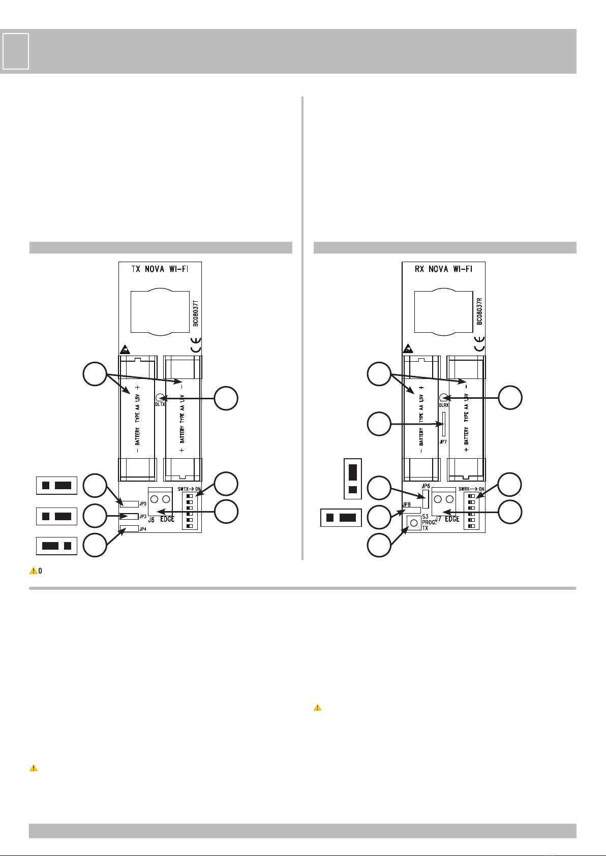
PORTÉE
Il est possible de choisir la portée des cellules photo-électriques en positionnant un cavalier
sur le ou les émetteurs.
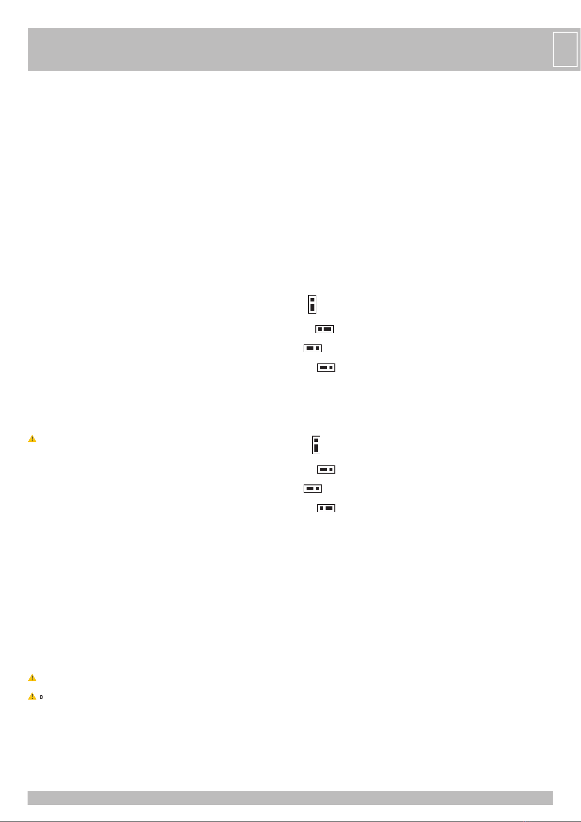
Cavalier JP5 en position 13 m de portée
JP5
Cavalier JP5 en position 25 m de portée (réglage d’usine)
JP5
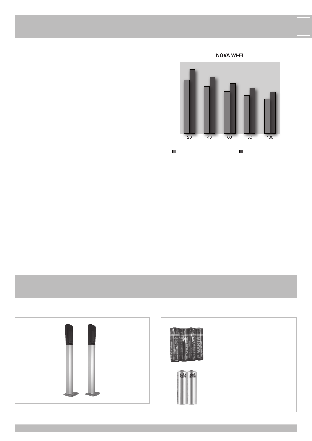
Avec JP5, avec portée réglée à 13 m, les batteries peuvent durer plus que 4 ans.
Avec JP5, avec portée réglée à 25 m, les batteries durent 3 ans.
Ces durées sont prévues avec 20 manoeuvres au jour pour tout l’an.
Une fois les appliques en plastique des cellules photo-électriques NOVA fixées, insérer les
cartes électroniques dans les slots appropriés placés sur les appliques et les fixer avec les
vis fournies.
INSTALLATION DES PILES
- Insérer les 2 piles alcalines type AA de 1,5V en faisant
attention à la polarité (voir image ci-contre).
- Si les piles ont été correctement installées dans l’émetteur TX
NOVA Wi-Fi, la LED verte devrait rester allumée pendant 10 s.
La LED s’éteint ensuite pour ne pas consommer inutilement
l’énergie des piles, mais l’émission du faisceau infrarouge est
toujours active.
- Si les piles ont été correctement installées dans le récepteur
RX NOVA Wi-Fi, la LED rouge doit rester allumée pendant 3 s.
- Si la LED rouge reste allumée, les photocellules sont déjà
alignées correctement.
- Si la LED rouge s’éteint, effectuer l’alignement du faisceau
infrarouge comme le décrit le paragraphe suivant.
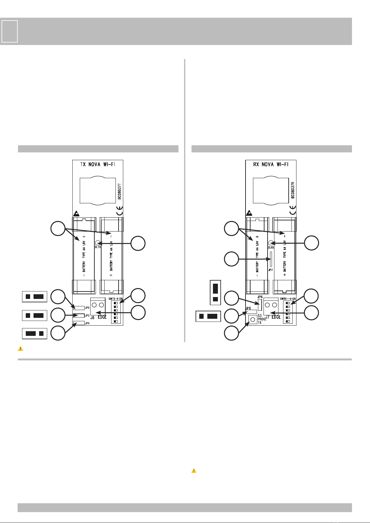
ALIGNEMENT ET SYNCHRONISATION DU FAISCEAU INFRAROUGE
- Les photocellules NOVA Wi-Fi sont construites avec un alignement central, cependant il
est possible si nécessaire d’effectuer un réglage des groupes optiques de l’émetteur et du
récepteur (+90°/-90° horizontalement et +5°/-5° verticalement).
- Appuyer sur la touche S3 PROG. TX présente sur le récepteur NOVA Wi-Fi pour activer le
faisceau pendant 3 minutes (temps nécessaire pour effectuer l’alignement entre l’émetteur
et le récepteur).
La LED rouge s’éteint après 3 minutes pour ne pas consommer inutilement l’énergie des
piles, cependant il est possible de renouveler l’opération pour 3 minutes supplémentaires
en rappuyant simplement sur la touche S3 PROG. TX.
- Si l’alignement est réussi, la LED rouge présente sur le récepteur doit s’allumer fixement et
indiquer la réception du faisceau infrarouge créé par l’émetteur. Si la LED rouge clignote, cela
signifie que le faisceau est faible et que l’alignement doit être mis au point jusqu’à ce que la
LED rouge s’allume fixement.
- Si le récepteur et l’émetteur sont montés à une distance inférieure à 13 mètres, il est conseillé
de positionner le cavalier JP5 comme indiqué dans le paragraphe “PORTÉE”, de cette manière
on réduit l’utilisation des piles et on augmente leur durée de vie.
- Monter l’écran de protection.
IDENTIFICATION
Chaque paire de photocellules NOVA Wi-Fi est munie de DIP sur OFF pour éviter la consommation
des piles quand elles ne sont pas utilisées (si elles sont reliées).
Chaque paire de photocellules NOVA Wi-Fi doit être OBLIGATOIREMENT identifiée en configurant
sur ON un seul des 6 DIP présents sur la carte. Exemple: régler DIP 1 ON sur MASTER WI-Fi, DIP 1
ON sur le récepteur NOVA Wi-Fi et DIP 1 ON sur l’émetteur NOVA Wi-Fi.
IDENTIFIER LES BOÎTIERS DES PHOTOCELLULES NOVA Wi-Fi EN APPLIQUANT L’ÉTIQUETTE FOURNIE
À L’EXTÉRIEUR DE CHAQUE BOÎTIER.
L’IDENTIFICATION EST UTILE POUR RECONNAÎTRE RAPIDEMENT LA PHOTOCELLULE QUAND SES
PILES SONT PRESQUE VIDES.
MÉMORISATION
Après avoir effectué l’alignement et l’identification des photocellules NOVA Wi-Fi, configurer
les DIP sur la carte MASTER Wi-Fi pour permettre aux photocellules de mémoriser (cette
opération peut également être effectuée après la procédure de mémorisation).
Pour effectuer la mémorisation, suivre la procédure suivante:
- Appuyer sur la touche PROG RX qui se trouve sur la carte MASTER Wi-Fi=> la LED EDGE PHOT
1clignotera en rouge pendant 1 minute (temps nécessaire pour effectuer la mémorisation).
12/24V ac/dc
PROG RX LED EDGE PHOT
- Appuyer sur la touche PROG TX qui se trouve sur le récepteur avec le DIP 1 sur ON => la
LED EDGE PHOT 1 présente sur le MASTER Wi-Fi passera du rouge clignotant au vert et un
bip préviendra de la mémorisation de la photocellule. À ce moment là, la LED EDGE PHOT
2s’allumera et clignotera rouge pendant 1 minute (temps nécessaire pour effectuer la
mémorisation).
Si d’autres photocellules ne sont pas mémorisées, patienter 1 minute ou bien appuyer sur
la touche PROG. RX 4 fois pour terminer la procédure de mémorisation (la LED EDGE PHOT 2
s’éteindra) => toutes les LED EDGE PHOT doivent rester éteintes pendant le fonctionnement
normal de l’appareil.
POUR MÉMORISER D’AUTRES PHOTOCELLULES NOVA Wi-Fi:
- Appuyer sur la touche PROG. TX sur la photocellule avec le DIP 2 sur ON => la LED EDGE PHOT
2présente sur le MASTER Wi-Fi passera du rouge clignotant au vert et un bip préviendra de la
mémorisation de la photocellule.
- Effectuer la même procédure pour mémoriser d’autres photocellules (jusqu’à 4 maximum).
⚠
à la fin de la procédure de mémorisation et après avoir habilité les DIP respectifs aux
sécurités mémorisées sur la carte MASTER Wi-fi, effectuer un balayage des LED s EDGE
PHOT en appuyant 6 fois sur la touche PROG RX.
CONTRÔLE DU FONCTIONNEMENT
Une fois la procédure de mémorisation terminée, contrôler le fonctionnement entre les
photocellules NOVA Wi-Fi et la carte MASTER Wi-Fi de la manière suivante:
- Appuyer sur la touche S3 PROG. TX présente sur une RX NOVA Wi-Fi pour activer la LED rouge
pendant 3 minutes.
- Contrôler qu’en interposant un obstacle la LED rouge s’éteigne et qu’en même temps la LED
correspondante EDGE PHOT présente sur la MASTER Wi-Fi s’illumine en vert pendant la durée
de l’interposition.
Même la LED DL3 de la carte MASTER Wi-Fi doit s’éteindre pour signaler le bon changement du
contact dédié à l’entrée PHOT se trouvant sur le boîtier
de commandes du moteur.
Répéter le contrôle sur les autres photocellules NOVA Wi-Fi installées.
Effectuer ensuite un contrôle de fonctionnement de toutes les photocellules installées en
activant le mouvement de l’automatisme et en contrôlant que l’interposition d’un obstacle
arrête/inverse (si automatisme en fermeture) le mouvement, ou qu’elle arrête/continue à
ouvrir (si automatisme en ouverture).
ANTENNE
L’antenne de communication radio est déjà reliée à tous les récepteurs NOVA Wi-Fi. NE PAS LA
TOUCHER !!!
CONTRÔLE DU SIGNAL D’ALARME
Vérifier qu’en enlevant une pile du récepteur photocellule avec DIP sur ON (par exemple 3
sur ON), et en demandant l’ouverture de la porte, la LED EDGE PHOT 3 sur la MASTER Wi-Fi
s’allume vert/rouge, pendant que les LED DL2 et DL3 s’éteignent et que le bipeur émette un
son entrecoupé pendant 1 minute.
Répéter le contrôle sur les autres photocellules NOVA Wi-Fi installées.
⚠
si en enlevant une pile du récepteur photocellule et en demandant l’ouverture de la porte,
le bipeur sur la carte MASTER Wi-Fi ne s’actionne pas, le DIP 3 sur MASTER Wi-Fi est sur OFF
(non habilité). Le positionner sur ON.
F

11
ÉTAT D’ATTENTION (signal de remplacement imminent des piles)
L’état d’attention (WARNING) avertit l’utilisateur d’un remplacement imminent des piles.
Quand les piles presque vides atteignent les 2,3V de puissance, la photocellule du récepteur
signale via radio à la MASTER Wi-Fi que les piles sont presque vides et le bipeur de MASTER Wi-Fi
émettra un bip toutes les 3 s pendant 1 minute.
L’état d’attention se renouvelle pendant 1 minute après une demande d’ouverture de la porte.
La LED EDGE PHOT sur MASTER Wi-Fi correspondant à la photocellule avec piles presque vides
s’allume fixement en rouge.
Pendant ces avertissements le système est toujours en état de marche, mais il est
recommandé de s’occuper du changement des piles au plus vite, pour éviter le blocage de la
porte qui survient quand la puissance des piles n’est plus que de 2,0 V.
Le clignotant SPARK Wi-Fi change le mode de clignotement pendant l’état d’attention en
effectuant 2 clignotements rapprochés suivis de 2 s de pause.
ÉTAT D’ALARME
L’état d’alarme s’active quand les piles sont complètement vides (2,0 V) ou quand la
photocellule est en panne.
Sur MASTER Wi-Fi les LED DL2 et DL3 s’éteignent et bloquent l’automatisme car le
fonctionnement d’une des photocellules installées n’est pas garanti.
Sur MASTER Wi-Fi (fw 01_04_13) la LED correspondant à la photocellule en panne ou dont
les piles sont vides clignote rouge et le bipeur émet un son toutes les 3 s pendant 1 minute,
attirant l’attention de l’utilisateur, qui devra soit changer les piles soit réparer la photocellule.
L’état d’attention se renouvelle pendant 1 minute après une demande d’ouverture de la porte.
POUR RETIRER LA CELLULE DÉFECTUEUSE, CONSULTER LE MANUEL DU MASTER WI-FI.
REMPLACEMENT DES PILES
La durée de vie des piles des photocellules NOVA Wi-Fi est d’environ 3 ans.
- Identifier la photocellule en panne en regardant la LED EDGE PHOT sur la carte MASTER Wi-Fi.
- Identifier grâce au numéro de la paire de photocellules dont les piles sont vides, qui se situe
à côté de la LED qui:
- clignote alternativement rouge/vert (si en état d’alarme)
- MASTER Wi-Fi fw 01_04_13 clignote rouge (si en état d’attention)
- est allumée vert fixe (si les piles de l’émetteur NOVA Wi-Fi sont vides)
- Chercher sur le boîtier des photocellules installées l’étiquette portant le numéro
d’identification correspondant.
- Remplacer les piles sur le récepteur et sur l’émetteur en respectant le sens des polarités.
- Appuyersurla touche PROG TX de la photocellule enquestionpourréactiver le fonctionnement
de la MASTER Wi-Fi. Si le bipeur de la MASTER Wi-Fi est en marche, il doit s’éteindre. Les LED
DL2- DL3 (si en état d’alarme) s’allument et la LED EDGE PHOT correspondant à la photocellule
dont on vient de changer les piles s’éteint.
L’automatisme est prêt à se remettre en marche en toute sécurité.
⚠
Nous vous rappelons que les piles doivent être éliminées selon les normes en vigueur. En
cas de destruction des photocellules, nous vous rappelons de retirer les piles et de les
éliminer selon les normes en vigueur.
AJOUT D’AUTRES PHOTOCELLULES NOVA Wi-Fi (MAX 6 TOTALI)
Si après l’installation, vous décidez d’installer d’autres photocellules pour augmenter la
sécurité de la porte, il est conseillé de:
- Débrancher le fusible de la porte.
- Fixer la paire supplémentaire de photocellules dans la position souhaitée.
- Effectuer la programmation en positionnant sur ON un DIP différent de ceux des autres
photocellules ou sécurités déjà installées et apposer l’étiquette chiffrée correspondante
pour l’identifier (voir paragraphe “Identification”).
- Activer sur la carte MASTER Wi-Fi le DIP correspondant à la photocellule ajoutée.
- Rebrancher la porte.
Effectuer les procédures de mémorisation et de contrôle comme indiqué précédemment.
PROCEDURE D’EFFACEMENT D’UNE SEULE SECURITE (PHOTOCELLULE OU BARRE
PALPEUSE) EN CAS DE PANNE OU SUBSTITUTION
Pour effectuer l’effacement d’une seule sécurité mémorisée sur MASTER Wi-Fi, procéder de
la manière suivante:
- Appuyer une ou plusieurs fois sur la touche PROG. RX pour sélectionner la LED EDGE PHOT
verte clignotante correspondant à la sécurité qu’il faut effacer.
- Une fois la sécurité sélectionnée, appuyer et maintenir appuyée la touche PROG. RX pendant
10 s.
- A la fin des 10 s, la LED EDGE PHOT clignote 6 fois rouge/vert en alternance, afin de signaler
l’effacement de la sécurité.
⚠
Positionner le DIP correspondant à la sécurité effacée sur OFF, puis effectuer un balayage
des LED s en appuyant 6 fois sur la touche PROG. RX.
⚠
Retirez les piles de la sécurité éliminés.
LIAISON DU CONTACT NET DE BARRES PALPEUSES MECANIQUES OU DE
RESISTIVES AUX PHOTOCELLULES NOVA Wi-Fi
Il est possible de connecter des barres palpeuses mécaniques ou résistives aux émetteurs et
aux récepteurs NOVA Wi-Fi.
Pour les liaisons des cordons au trasmetteur ou à l’écouter de la photocellule NOVA Wi-Fi,
utiliser un câble de 2 x 0,5 mm2avec diamètre extérieur maximum 5 mm. En cas on utilise
un câble de diamètre inférieur, il est opportun vérifier que la galoche donne garantie de PAS
infiltration de l’eau, donc pour maintenir le degré de protection IP44, fermer hermétiquement
avec silicone les eventuelles ouvertures autour du câble.
LES PERFORMANCES DE BARRE PALPEUSE MECANIQUE OU RESISTIVE CHANGENT SELON SON
POSITIONNEMENT, PORTER UNE ATTENTION PARTICULIÈRE À CE QUI SUIT:
La barre palpeuse connectée au récepteur NOVA Wi-Fi:
- si activée lorsque le portail se FERME => CHANGE LE MOUVEMENT EN OUVERTURE;
- si activée lorsque le portail s’OUVRE => CHANGE LE MOUVEMENT EN FERMETURE.
ELLE AGIT DONC COMME UNE BARRE PALPEUSE.
La barre palpeuse connectée à l’émetteur NOVA Wi-Fi:
- si activée lorsque le portail se FERME => CHANGE LE MOUVEMENT EN OUVERTURE;
- si activée lorsque le portail s’OUVRE => ARRÊTE ET ENSUITE LAISSE CONTINUER L’OUVERTURE.
ELLE AGIT DONC COMME UNE PHOTOCELLULE.
POUR DES BARRES PALPEUSES MECANIQUES TOUCH (code ACG3015) AVEC CONTACT N.C.
- Connecter en série au contact N.C. de la barre palpeuse mécanique une résistance de 8,2 KΩ
(sans une telle résistance le système ne peut pas fonctionner et se met en état d’alarme -
voir tableau “EN CAS DE DIFFICULTÉ).
- Connecter aux bornes J6 de l’émetteur ou J7 du récepteur le contact N.C. de la barre palpeuse.
- Placer sur le récepteur le cavalier JP6 dans la position suivante pour activer la barre palpeuse:
JP6
- Placer sur le récepteur le cavalier JP8 dans la position suivante pour gérer le contact N.C.:
JP8
- Placer sur l’émetteur le cavalier JP3 dans la position suivante pour activer la barre palpeuse:
JP3
- Placer sur l’émetteur le cavalier JP4 dans la position suivante pour gérer le contact N.C.:
JP4
POUR DES BARRES PALPEUSES RESISTIVES AVEC CONTACT N.O.
- Connecter en parallèle au contact N.O. de la barre palpeuse résistive une résistance de 8,2
KΩ (sans une telle résistance le système ne peut pas fonctionner et se met en état d’alarme
- voir tableau “EN CAS DE DIFFICULTÉ).
- Connecter aux bornes J6 de l’émetteur ou J7 du récepteur le contact N.O. de la barre palpeuse.
- Placer sur le récepteur le cavalier JP6 dans la position suivante pour activer la barre palpeuse:
JP6
- Placer sur le récepteur le cavalier JP8 dans la position suivante pour gérer le contact N.O.:
JP8
- Placer sur l’émetteur le cavalier JP3 dans la position suivante pour activer la barre palpeuse:
JP3
- Placer sur l’émetteur le cavalier JP4 dans la position suivante pour gérer le contact N.O.:
JP4
F

12
F
FONCTION PARTICULIÈRE
IL EST POSSIBLE, AVEC LE RÉCEPTEUR NOVA Wi-Fi, ET VIA LE CAVALIER JP7, DE FAIRE FONCTIONNER
LA PHOTOCELLULE COMME UNE BARRE PALPEUSE.
Effectuer la procédure suivante:
- Retirer les piles du récepteur NOVA Wi-Fi.
- Couper le cavalier JP7.
- Remettre les piles.
- Effectuer la mémorisation sur MASTER Wi-Fi.
- Si la photocellule a déjà été mémorisée, effectuer une élimination de la position mémorisée,
et ensuite mémoriser la nouvelle configuration.
MAINTENANT, SI LES PHOTOCELLULES SONT INTERCEPTÉES, ELLES AGISSENT COMME DES BARRES
PALPEUSE MECANIQUES OU RESISTIVES EN OUVERTURE ET EN FERMETURE.
Cette fonction sert à sécuriser les zones non sujettes au passage des véhicules, c’est-à-dire
seulement les zones de passage piéton (zone dans laquelle coulisse la partie mobile du portail
lorsqu’il s’ouvre ou zone entre les vantaux des battants et les murs latéraux vers lesquels ils
s’ouvrent) pour protéger les personnes en cas de présence dans ces zones.
EN CAS DE DIFFICULTÉ
SYMPTOME CONTRÔLE
La LED verte DLTX de l’émetteur ne s’allume pas après insertion des piles. - Vérifier que les piles ont été correctement installées, en respectant les polarités, OU
- Changer les piles.
La LED rouge DLRX du récepteur ne s’allume pas après insertion des piles. - Vérifier que les piles ont été correctement installées, en respectant les polarités, OU
- Changer les piles.
Le bipeur sur MASTER Wi-Fi émet un son toutes les 3 s pendant 1 minute et la porte continue
à fonctionner.
Remplacer au plus vite les piles de la (des) photocellule(s).
Le bipeur sur MASTER Wi-Fi émet un son entrecoupé pendant 1 minute, et la porte ne se met
pas en mouvement.
Remplacer les piles de la (des) photocellule(s).
La porta ne s’ouvre pas. - Photocellule non alignée, occupée ou piles de l’émetteur déchargées, OU
- Résistance de 8,2 KΩ non connectée en série au contact N.C. ou en parallèle au contact N.O. de
la barre palpeuse reliée à l’émetteur ou au récepteur.
La porta ne s’ouvre pas, le bipeur sur MASTER Wi-Fi (fw 01_04_13) émet un son toutes les 3 s et
une des LED s s’allume rouge.
Piles déchargées sur le récepteur NOVA Wi-Fi.
La barre palpeuse connectée à l’émetteur ou au récepteur n’agit pas en tant que sécurité. Vérifier que les cavaliers ont bien été positionnés sur l’émetteur et sur le récepteur NOVA Wi-Fi.
En appuyant sur la barre palpeuse résistive avec contact N.O. connectée au récepteur, le bipeur
émet 5 sons consécutifs.
Le cavalier JP8 est configuré comme contact N.C., le placer sur N.O.
En appuyant sur la barre palpeuse mécanique avec contact N.C. connectée au récepteur, le
bipeur émet 5 sons consécutifs.
Le cavalier JP8 est configuré comme contact N.O., le placer sur N.C.
Les batteries du Recepteur NOVA Wi-Fi se déchargent après quelque mois. - Fixer le circuit du Recepteur NOVA Wi-Fi afin qu’il voit la fiche MASTER Wi-Fi, OU
- Installer une antenne 868 MHz (code ACG5451) au MASTER Wi-Fi pour garantir la reception du
signal radio.
JP7

13
F
CARACTÉRISTIQUES TECHNIQUES
RÉCEPTEUR NOVA Wi-Fi
- ALIMENTATION piles 2 x AA 1,5 V (>2,7Ah)
- CONSOMMATION AU REPOS 5 µA
- CONSOMMATION MAX 25 mA
- TYPE DE MODULATION FSK
- DURÉE DE VIE DES PILES environ 3 ans
- TEMPÉRATURE DE TRAVAIL -20 ÷ +60°C
- TEMPS D’ACTIVATION DE L’ÉCOUTER LORSQUE ENGAGÉ 90 ms
- TEMPS DE RÉTABLISSEMENT À LA LIBÉRATION 90 ms
- EXTÉRIEUR en polycarbonate
- BASE en ABS
- DEGRÉ DE PROTECTION IP44
- DIMENSIONS 150x45x41 mm
- POIDS 0,150 kg
DONNÉES TECHNIQUES SIGNAL ET FRÉQUENCE D’ONDES
- FREQUENCE 868,3 MHz
- SENSIBILITÉ -108 dBm
- PUISSANCE D’ÉMISSION <25 mW
- PORTÉE 20 m en espace libre sans antenne
ÉMETTEUR NOVA Wi-Fi
- ALIMENTATION piles 2 x AA 1,5 V (>2,7Ah)
- ABSORPTION 3 µA
- TYPE DE MODULATION FSK
- DURÉE DE VIE DES PILES environ 3 ans
- VIE BATTERIES AVEC JUMPER JP5 SUR PORTÉE 13 m 4 ans (20 cycles/jour)
- VIE BATTERIES AVEC JUMPER JP5 SUR PORTÉE 25 m 3 ans (20 cycles/jour)
- TEMPÉRATURE DE TRAVAIL -20°C ÷ +60°C
- EXTÉRIEUR en polycarbonate
- BASE en ABS
- DEGRÉ DE PROTECTION IP44
- DIMENSIONS 150x45x41 mm
- POIDS 0,150 kg
DONNÉES TECHNIQUES FAISCEAU INFRAROUGE
- LONGUEUR D’ONDE 890 nm
- PORTÉE 25 m
- DIMENSIONS DE LA ZONE DE RELEVÉ Ø 20 mm
ENTRETIEN RÉGULIER
Il doit être effectué seulement de personnel autorisé en accord avec les règles de sûreté et avec
les instructions du fabricant, avec la fréquence semestrielle.
- Les dispositifs de sûreté doivent être maintenus en conditions de travail efficaces et en accord
avec les instructions du fabricant.
- Vérifier la présence et la lisibilité du marquage initial.
- Substituer les batteries lorsque demandé du système (voir tableau EN CAS DE DIFFICULTÉ).
- Nettoyer les écrans de protection CPL1311 avec chiffon humidifié.
- Substituer les écrans de protection CPL1311, si endommagés et s’ils ne garantissent pas le
segnale parmi ÉMETTEUR et RÉCEPTEUR; de toute façon les substituer après 10 ans.
OPTIONS
PAIRE DE POTEAUX pour NOVA
H = 0,5 m code ACG8039
BATTERIES
BATTERIES ALCALINES AA
4 X 1,5V - avec NOVA Wi-Fi vie batteries 3 ans.
code ACG9519
BATTERIES LITHIO AA
2 X 1,5V - avec NOVA Wi-Fi vie batteries 4 ans (prendre
2 pièces).
Pour des températures extrêmes -40÷+60°C.
code ACG9509
0
1
2
3
4
20 40 60 80 100
Ans
Cycles au jour
durée piles alcalines durée piles lithio

14
REFERENCE TO STANDARDS FOR AUTOMATIC GATES AND DOORS
The installer must ensure that the installation of the NOVA Wi-Fi photocells is performed
only in the presence of further protection as specified by standard EN 12453 in 5.1.3 (general
protection requirements).
RIB MAY NOT BE HELD RESPONSIBLE FOR DAMAGES CAUSED BY IMPROPER, WRONG OR
UNREASONABLE USE.
Usage restrictions: The NOVA Wi-Fi photocells cannot be used on devices excluded by the
application of the EN 12978, such as:
- protection devices for the installation on doors used for a different purpose to those ones
used for pedestrian or veheicle access, covered by the norm which principal intent is that
of allowing a safe access to industrial, commercial, public and commercial sites. Some
examples of excluded accesses can be: sluice gates, dams, lift doors, vehicles’ doors, doors
used mainly to restrain animals, theatre curtains, railways barriers, barriers used only for
vehicles.
- Devices used only fo the standard control and for the stopping, including the emergency
stopping, of motorized doors.
- Safety systems and safety devices used on machineries different from doors.
⚠
Any possible modification of the device, or of the configuration of the same cannot
be carried out without the clear authorization by the manufacturer or, by the local
authorized dealer.
The installer of the safety device must make sure that the end user know the following:
- That the safety devices must be made known to all appropriate people.
- That the passages to reach the devices must be kept clear from any obtsacle.
- About the procedures for cleaning so to avoid the dangerous building up of material.
- The possible details for a restart of the system after an emergency or accidental stop caused
by the control system.
Any modification of the project or, of the configuration of the device, without discussing it
first with the manufacturer or with the local autorized dealer can cause dangerous situations.
USES
NOVA Wi-Fi photocells communicate constantly and exclusively with the MASTER Wi-Fi card
and completely meet the active security demands of all types of automatic opening systems.
⚠
If you remove the power of the MASTER Wi-Fi for a long time, the TOUCH Wi-Fi safety
edges and the NOVA Wi-Fi photocells will exhaust faster than normal the charging of their
batteries. Keep the MASTER Wi-Fi always properly fed to ensure a period of three years for
the batteries-life, as stated by RIB.
If for instance, the power to the system is cut off every night, the photocells and the safety
edges will regularly and constantly search for the MASTER Wi-Fi without finding it. Therefore,
the life span of the batteries may be reduce to less than one year.
NOVA Wi-Fi PHOTOCELLS ARE ONLY ON DURING DOOR OPERATION. THANKS TO THE SLEEP MODE.
WHEN THE DOOR IS NOT MOVING THE PHOTOCELLS ARE OFF TO ALLOW FOR LONGER BATTERY LIFE.
TRANSMITTER SETTINGS AND CONNECTIONS
J6 Terminals for the connection of the clean contact of the mechanical or inductive
safety edge (N.C. or N.O.).
SWTX Micro-switches for coordination and identification
JP3 Safety edge enabling/disabling jumper (standard jumper not inserted for
unconnected safety edge. Disable the jumper if a safety edge is connected)
JP4 Safety edge contact selector jumper N.O./N.C. (factory setting N.C.)
JP5 Range selector jumper 13/25 m (factory setting 25 m)
BAT Alkaline batteries 2 x AA 1,5V
DLTX Green LED function indicator
RECEIVER SETTINGS AND CONNECTIONS
J7 Terminals for the connection of the clean contact of the mechanical or
inductive safety edge (N.C. or N.O.).
SWRX Micro-switches for coordination and identification
S3 PROG. TX Push-button for memorization and alignment
JP6 Safety edge enabling/disabling jumper (standard jumper not inserted
for unconnected safety edge. Disable the jumper if a safety edge is
connected)
JP7 Jumper wire for photocell or safety edge selection (factory setting
contacts closed)
JP8 Safety edge contact selector jumper N.O./N.C. (factory setting N.C.)
BAT Alkaline batteries 2 x AA 1,5V
DLRX Red LED indicating correct power and infrared signal alignment
⚠
EACH TIME A NEW JUMPER CONFIGURATION IS USED IT IS NECESSARY TO TURN OFF AND TURN ON POWER TO BOTH THE TRANSMITTER AND THE RECEIVER.
STANDARD POSITIONS OF THE JUMPERSSTANDARD POSITIONS OF THE JUMPERS
JP7
JP6
JP8
S3
BAT
SWRX
J7
DLRX
JP4
JP3
BAT
JP5
DLTX
SWTX
J6
G
B

15
NOVA Wi-Fi photocells may be installed very close together thanks to SYNCHRONIZATION.
SYNCHRONIZATION is guaranteed for up to 2 pairs of photocells with DIP 1 ON (1st pair) and DIP
2 ON (2nd pair).
Another 2 pairs of photocells may be installed, with transmission/reception inverted from that
of the 2 previous pairs.
DIPes must be set: DIP 3 ON (3rd pair) and DIP 4 ON (4th pair).
They are produced in versions for wall mounting, for mounting to columns of iron or other
smooth material, or on dedicated SUPPORT COLUMNS code ACG8039.
⚠
Before placing the drilling template
(code CVA1940) make sure that the
contact surface is clean.
- Affix the plastic bases CPL1312 to the
pillars or columns about 40÷60 cm
from the ground and at a maximum
distance of 10 cm from the conveyance
or pressure area or immediately out of
range of any protruding edge.
- After adjustment attach the protective
casing CPL1311.
- Install the NOVA Wi-Fi receiver a
maximum distance of 20 m from
the MASTER Wi-Fi card in order to allow
correct radio function and in a shaded
area or in a position not exposed to
horizontal sunlight for correct infrared
signal operation.
- In every case it is advisable to place the
photocells at the same height and in line
with each other.
- For the correct positioning of the
photocells refer to the user installation
manual or to standard EN12453.
MOUNTING
CPL1311 CPL1312
BC08037R
BC08037T CVA1940
⚠
THE RECEIVER OF THE PHOTOCELLS MUST BE IN CLEAR VIEW OF THE MASTER Wi-Fi BOARD
NO OBSTACLES SUCH AS WALLS, PILLARS OR METAL CABINETS MUST BE PRESENT BETWEEN THE RECEIVER OF THE NOVA Wi-Fi PHOTOCELLS AND THE MASTER Wi-Fi BOARD.
If it is not possible to avoid that because the obstacles cannot be removed, please install an 868 MHz aerial (code ACG5451) on the MASTER Wi-Fi and position it so to guarantee a good quality
radio communication between the parts.
This solution also prevents the quick discharge of the batteries on the NOVA Wi-Fi.
G
B
RX PHOT 3 TX PHOT 3
TX PHOT 1 RX PHOT 1
TX PHOT 2 RX PHOT 2
RX PHOT 4 TX PHOT 4

16
⚠
It is possible to connect both the transmitter and the receiver to mechanical or resistive
safety edges as shown in the paragraph “CONNECTION OF MECHANICAL OR RESISTIVE
SAFETY EDGE”.
RANGE
It is possible to adjust the range of the photocells by placing a jumper on the transmitter(s).
Jumper JP5 with a range of 13 m
JP5
Jumper JP5 with a range of 25 m (factory setting)
JP5
With JP5 set on 13 m range, the batteries can last more than 4 years.
With JP5 set on 25 m range, the batteries will last 3 years.
That is based on 20 daily complete operations every day of the year.
After affixing the plastic bases of the NOVA Wi-Fi photocells, insert the circuit boards into the
proper places on the bases and attach them with the supplied screws.
BATTERY CONNECTION
- Insert the two AA 1,5V Alkaline batteries checking that the
polarity is correct (see side image).
- Upon insertion of the batteries into the transmitter TX NOVA
Wi-Fi the green LED will light for 10 s indicating that it works
correctly. The LED then shuts off so as not to waste battery
energy, but the infrared signal is active.
- Upon insertion of the batteries into the receiver RX NOVA Wi-Fi
the red LED will light for 3 s indicating that it works correctly.
- If the red LED remains lit then the photocells are already
aligned correctly.
- If the red LED turns off, align the infrared signal as described
in the next paragraph.
ALIGNMENT AND SYNCHRONIZATION OF THE
INFRARED SIGNAL
- NOVA Wi-Fi photocells are packaged with central alignment however, if necessary, it is
possible to adjust the optical units of the transmitter and receiver (+90°/-90° horizontally
and +5°/-5° vertically).
- Push the button S3 PROG. TX on the NOVA Wi-Fi receiver to activate it for 3 minutes (the time
necessary to perform the alignment between the transmitter and receiver). ATTENTION: After
3 minutes the red LED shuts off so as not to waste battery energy, in any case it is possible to
restart the 3 minute period simply by pushing again on the button S3 PROG. TX.
- After performing the alignment the red LED on the NOVA Wi-Fi receiver must emit a constant
light to indicate correct reception of the infrared signal from the NOVA Wi-Fi transmitter.
If the red LED is flashing it means that the signal is weak and that the alignment must be
improved until the red LED emits a constant light.
- If the transmitter and the receiver are mounted at a distance of less than 13 meters, we
recommend positioning the jumper JP5 as indicated in the paragraph “RANGE”. This will
provide lower battery consumption and consequently add to their duration.
- Mount the protective cover.
IDENTIFICATION
Every pair of NOVA Wi-Fi photocells is supplied with the DIPes in the OFF position to avoid
battery consumption when not in use (if connected).
Every pair of NOVA Wi-Fi photocells must OBLIGATORILY be unequivocally identified by placing
only one of the 6 different DIPes on the card into the ON position. Example: set DIP 1 to ON on
the MASTER Wi-Fi, DIP 1 to ON on the NOVA Wi-Fi receiver and DIP 1 to ON on the NOVA Wi-Fi
transmitter.
IDENTIFY THE NOVA Wi-Fi PHOTOCELL CONTAINERS BY APPLYING THE ADHESIVE SAFETY EDGE ON
PROVIDED ON THE OUTSIDE OF EVERY CONTAINER.
IDENTIFICATION HELPS TO QUICKLY IDENTIFY THE PHOTOCELL WHEN ITS BATTERIES ARE LOW.
MEMORIZATION
After aligning and identifying the NOVA Wi-Fi photocells, set the DIPes on the MASTER Wi-Fi
card to enable the photocell to be memorized (this operation may also be performed after the
memorization procedure).
To perform memorization use the following procedure:
- Push the button PROG RX found on the MASTER Wi-Fi=> card. The EDGE PHOT LED 1 will flash
red for 1 minute (the time necessary to perform memorization).
12/24V ac/dc
PROG RX LED EDGE PHOT
- Push the button PROG TX on the receiver with DIP 1 set to ON => on the MASTER Wi-Fi the
EDGE PHOT LED 1 flashing red will turn green and a buzzer will signal that memorization of the
photocell has been done correctly. At the same time the EDGE PHOT LED 2 will begin flashing
red for 1 minute (the time necessary to perform memorization).
If there are no other photocells to be memorized let a minute pass or push the button PROG.
RX 4 times to complete the memorization procedure (the EDGE PHOT LED 2 shuts off) => all of
the LEDs EDGE PHOT should be off during normal operation.
TO MEMORIZE OTHER NOVA Wi-Fi PHOTOCELLS:
- Push the button PROG TX on the receiver with DIP 2 set to ON => on the MASTER Wi-Fi the
EDGE PHOT LED 2 flashing red will turn green and a buzzer will signal that memorization of
the photocell has been done correctly.
- Follow the same procedure for any other photocells (up to a maximum of 4).
NOTE: at the end of the memorization procedure and after having enabled the DIPes for the
safety devices memorized on the MASTER Wi-Fi, run a scan on the EDGE PHOT LED pushing the
button PROG. RX 6 times.
SYSTEM CHECK
After finishing the memorization procedure, check the correct working order between the
NOVA Wi-Fi photocells and the MASTER Wi-Fi by doing the following:
- Push the button S3 PROG. TX on a RX NOVA Wi-Fi to activate the red LED for 3 minutes.
- Place an object between them and check that the red LED turns off and that at the same
time on the MASTER Wi-Fi the corresponding EDGE PHOT LED is on and green while the object
is present.
- The LED DL3 of the MASTER Wi-Fi should also turn off indicating the correct exchange of
dedicated contact with the PHOT entry on the motor control panel.
Repeat the process on the other NOVA Wi-Fi photocells installed.
Then perform a system check of all the photocells installed by activating the movement of the
automation and checking that when an object is present the automation stops/reverses when
closing, or stops/continues to open when opening.
ANTENNA
The radio antenna is already connected to all of the NOVA Wi-Fi receivers.
DO NOT TOUCH IT !!!
ALARM CHECK
Check that by removing a battery from the photocell receiver with a DIP (example 3 set to
ON), and commanding the door to open, on the MASTER Wi-Fi the LED 3 alternates from red
to green, while LEDs DL2 and DL3 turn off, and the buzzer sound intermittently for 1 minute.
Repeat the process for any other photocells installed.
⚠
if when the battery from the photocell receiver is removed and commanding the door to
open the buzzer on the MASTER Wi-Fi does not sound, DIP 3 on the MASTER Wi-Fi is set to
OFF (disabled). Set it to ON.
WARNING (replace the batteries)
The WARNING tells the user of the immediate need to replace the batteries.
When battery power reaches 2,3V, the photocell receiver signals the MASTER Wi-Fi via radio
of the low battery status and activates the BUZZER of the MASTER Wi-Fi with a sound every
3 s for 1 minute.
The warning is renewed for 1 minute if a command is given to the door.
The LED on the MASTER Wi-Fi of the photocell with the low batteries emits a constant red light.
The system is still operational during these signals, but it is advantageous to replace the
batteries as soon as possible in order to avoid a full stop of the door operation which happens
when the batteries reach 2,0 V.
G
B

17
The SPARK Wi-Fi flashing light changes flash modes during the warning status; flashing 2 times
in quick succession followed by a 2 second pause.
ALARM STATUS
The alarm activates when the batteries have been exhausted (2,0 V) or when a photocell is
not working.
On the MASTER Wi-Fi LEDs DL2 and DL3 turn off, stopping the automation due to the fact that
one of the photocells installed is not working properly.
On the MASTER Wi-Fi (fw 01_04_13) the LED of the photocell with the low or exhausted battery,
lights flashing red and the buzzer emits a sound every 3 s for 1 minute to alert the user that
the batteries or the photocell need attention.
The alarm is renewed for 1 minute if a command is given to the door.
IN ORDER TO REMOVE THE SINGLE PHOTOCELL FROM THE Wi-Fi SYSTEM READ THE MASTER Wi-Fi
CARD MANUAL.
CHANGING THE BATTERIES
The duration of the batteries used for NOVA Wi-Fi photocells is about 3 years.
- Identify which photocell has the exhausted batteries by looking at the EDGE PHOT LED on the
MASTER Wi-Fi card.
EDGE PHOT LED on MASTER Wi-Fi:
- flashes red/green (if the alarm is on)
- MASTER Wi-Fi fw 01_04_13 lights flashing red (if the warning is on)
- stays on green (if the NOVA Wi-Fi transmitter batteries are exhausted)
- Locate the adhesive safety edge with the corresponding identity number of the photocells
on the outside of the container.
- Replace the batteries of both the transmitter and receiver checking that the polarity is
correct.
- Push the button PROG TX of the photocell receiver to reactivate the MASTER Wi-Fi. The buzzer
on the edge of the MASTER Wi-Fi card turns off and the LED DL2- DL3 (if the alarm is on) turn
on and the EDGE PHOT LED of the photocell with the replaced batteries turns off.
The automation is now ready to begin safe operation once more.
⚠
Please remember that batteries must be disposed of properly according to current
standards. In case of disposal of the photocells please remember to remove and dispose
of the batteries properly.
ADDING OTHER NOVA Wi-Fi PHOTOCELLS (UP TO 6 TOTAL)
If after installation the use of further photocells is desired to increase door safety, it is
recommended to:
- Turn off power to the door.
- Place the additional photocells in the desired position.
- Perform the programming by setting to ON a DIP different from that of the other photocells
or safety devices installed and identify it with the corresponding numbered adhesive safety
edge (see paragraph “Identification”).
- Enable the DIP of the added photocell on the MASTER Wi-Fi card.
- Return power to the door.
Follow the memorization procedure and system check as indicated previously.
REMOVAL PROCEDURE FOR A SINGLE SAFETY DEVICE (PHOTOCELL OR SAFETY EDGE)
FOR BREAKDOWN OR SUBSTITUTION
In order to remove a single memorized safety device on the MASTER Wi-Fi, use the following
procedure:
- Push the button PROG. RX one or more times to select the EDGE PHOT LED which begins
flashing green, corresponding to the safety device to be eliminated.
- After selecting the safety device, push and hold the button PROG. RX for 10 s.
- After 10 s the EDGE PHOT LED flashes alternately red and green 6 times, indicating successful
removal.
⚠
Place the DIP corresponding to the deleted safety device to OFF, then scan the EDGE PHOTO
LEDs pushing the PROG. RX button 6 times.
⚠
Remove the batteries from the deleted safety device.
CONNECTION OF THE MECHANICAL OR RESISTIVE SAFETY EDGES CLEAN
CONTACTS TO THE NOVA Wi-Fi PHOTOCELLS.
It is possible to connect mechanical or resistive safety edges to NOVA Wi-Fi transmitters and
receivers.
For the connection of the safety edges to the transmitter or receiver of the NOVA Wi-Fi
photocells, a 2 x 0,5 mm2cable with external diametre of 5 mm must be used.
When using wires and cables of smaller diametre, verify that the cable conector is thoroughly
water tight.
However, in order to ensure an IP44 protecion rating, it can be advisable to seal off with
silicone glue any opening that could allow the passage of water.
THE OPERATION OF THE SAFETY EDGE CHANGES ACCORDING TO ITS POSITION, THEREFORE PAY
ATTENTION TO THE FOLLOWING:
The safety edge connected to the NOVA Wi-Fi RECEIVER:
- if activated while the door is CLOSING => REVERSES THE OPENING MOVEMENT;
- if activated while the door is OPENING => REVERSES THE CLOSING MOVEMENT.
IT IS OPERATING AS A SAFETY EDGE.
The safety edge connected to the NOVA Wi-Fi TRANSMITTER:
- if activated while the door is CLOSING => REVERSES THE OPENING MOVEMENT;
- if activated while the door is OPENING => STOPS AND THEN ALLOWS OPENING TO CONTINUE.
IT IS OPERATING AS A PHOTOCELL.
FOR MECHANICAL TOUCH SAFETY EDGES (code ACG3015) WITH CONTACT N.C.
- Connect in series to the N.C. contact of the safety edge a resistance of 8,2 KΩ (without this
resistance the series will not work and the alarm will come on - see table “TROUBLESHOOTING’)
- Connect the safety edge N.C. contact to the feed terminals J6 for the transmitter or J7 for
the receiver.
- Place the jumper JP6 on the receiver in the following position to enable the safety edge:
JP6
- Place the jumper JP8 on the receiver in the following position to control the N.C. contact:
JP8
- Place the jumper JP3 on the transmitter in the following position to enable the safety edge:
JP3
- Place the jumper JP4 on the transmitter in the following position to control the N.C. contact:
JP4
FOR RESISTIVE SAFETY EDGES WITH N.O. CONTACT
- Connect in parallel to the N.O. contact of the safety edge a resistance of 8,2 KΩ (without this
resistance the series will not work and the alarm will come on - see table “TROUBLESHOOTING’)
- Connect the safety edge N.O. contact to the feed terminals J6 for the transmitter or J7 for
the receiver.
- Place the jumper JP6 on the receiver in the following position to enable the safety edge:
JP6
- Place the jumper JP8 on the receiver in the following position to control the N.O. contact:
JP8
- Place the jumper JP3 on the transmitter in the following position to enable the safety edge:
JP3
- Place the jumper JP4 on the transmitter in the following position to control the N.O. contact:
JP4
G
B

18
G
B
SPECIAL FEATURES
WITH THE NOVA Wi-Fi RECEIVER IT IS POSSIBLE TO MAKE THE PHOTOCELL FUNCTION AS A SAFETY
EDGE BY USING THE JUMPER JP7.
Perform the following procedure:
- Remove the NOVA Wi-Fi receiver battery.
- Cut the jumper JP7.
- Replace the battery.
- Perform memorization on the MASTER Wi-Fi
- If the photocell has already been memorized, perform a single cancellation of the previously
memorized position, and then proceed to memorize using the new configuration.
IF THE PHOTOCELLS ARE NOW INTERCEPTED, THEY WORK AS A SAFETY EDGE BOTH IN OPENING
AND IN CLOSING.
This function protects the area not used for pedestrian and not vehicular traffic (the motion
area of the door when opening or the area between the door panels and the side walls to which
they open) to protect individuals who may be present in these areas.
TROUBLESHOOTING
PROBLEM CHECK
The green LED DLTX of the transmitter does not come on when the battery is inserted. - Check that the polarity of the batteries is correct, OR
- Replace exhausted batteries
The red LED DLRX of the receiver does not come on when the battery is inserted. - Check that the polarity of the batteries is correct, OR
- Replace exhausted batteries
The MASTER Wi-Fi buzzer emits a sound every 3 s for 1 minute and the door continues to
function. Replace the batteries of the photocell(s) as they are low.
The MASTER Wi-Fi buzzer emits an intermittent sound for 1 minute, and the door does not move. Replace the batteries of the photocell(s) as they are low.
The door does not open.
- The photocell is not aligned, stuck or the transmitter has exhausted batteries, OR
- Resistance of 8,2 kΩ is not connected in series to the N.C. contact or in parallel to the N.O.
contact of the safety edge connected to the transmitter or receiver.
The door does not open, the MASTER Wi-Fi (fw 01_04_13) buzzer emits a sound every 3 s for 1
minute and one of the LED lights flashing red. The NOVA Wi-Fi receiver batteries are exhausted.
The safety edge connected to the transmitter or receiver does not act as a safety device. CheckthatthejumpersontheNOVA Wi-Fi transmitter or receiverhavebeenpositionedcorrectly.
Pushing the safety edge with an N.O. contact connected to the receiver, the buzzer emits 5
consecutive sounds. Jumper JP8 is configured as an N.C. contact, place it on N.O.
Pushing the safety edge with an N.C. contact connected to the receiver, the buzzer emits 5
consecutive sounds. Jumper JP8 is configured as an N.O. contact, place it on N.C.
The batteries of the Nova Wi-Fi Receiver discharge within a few months.
- Install the receiver of the photocells in clear view of the MASTER Wi-Fi board, OR
- Alternatvely, install an 868 MHz aerial (code ACG5451) on the MASTER Wi-Fi and position it so to
guarantee a good quality radio communication between the parts
JP7

19
G
B
TECHNICAL SPECIFICATIONS
NOVA Wi-Fi RECEIVER
- POWER batteries 2 x AA 1,5 V (>2,7Ah)
- ABSORPTION AT REST 5 µA
- MAXIMUM ABSORPTION 25 mA
- MODULATION TYPE FSK
- BATTERIE LIFE about 3 years
- TIME OF ACTIVATION OF THE RECEIVER WHEN ENGAGED 90 ms
- TIME OF RESET WHEN DISENGAGED 90 ms
- OPERATING TEMPERATURE -20 ÷ +60°C
- COVER in polycarbonate
- BASE in ABS
- PROTECTION LEVEL IP44
- DIMENSIONS 150x45x41 mm
- WEIGHT 0,150 kg
RADIO FREQUENCY SIGNAL TECHNICAL DETAILS
- FREQUENCY 868,3 MHz
- SENSITIVITY -108 dBm
- EMISSION POWER <25 mW
- RANGE 20 m in open spaces without antenna
NOVA Wi-Fi TRANSMITTER
- POWER batteries 2 x AA 1,5 V (>2,7Ah)
- POWER ABSORBED 3 µA
- MODULATION TYPE FSK
- BATTERY LIFE about 3 years
- BATTERY LIFE WITH JP5 SET ON 13 m RANGE 4 years (with 20 daily cycles)
- BATTERY LIFE WITH JP5 SET ON 25 m RANGE 3 years (with 20 daily cycles)
- OPERATING TEMPERATURE -20°C ÷ +60°C
- COVER in polycarbonate
- BASE in ABS
- PROTECTION LEVEL IP44
- DIMENSIONS 150x45x41 mm
- WEIGHT 0,150 kg
INFRARED SIGNAL TECHNICAL DETAILS
- WAVELENGTH 890 nm
- RANGE 25 m
- DIMENSION OF THE DETECTION AREA Ø 20 mm
ROUTINE MAINTENANCE
Must be carried out every six months, only by authorized personnel in agreement with the
safety rules and with the manufacturer’s instructions.
- The safety devices must be kept in efficient working conditions and in agreement with the
manufacturer’s instructions.
- Verify the presence and the possibility to read the initial marking.
- Replace the batteries when requested by the system (see the chart “IN CASE OF DIFFICULTIES”).
- Clean the protection screens CPL1311 with a wet cloth.
- Replace the protection screens CPL1311 if damanged, and if they do not guarantee the correct
communication between the TRANSMITTER and the RECEIVER; in any case replace them after
10 years.
ACCESSORIES
PAIR OF COLUMNS for NOVA
H = 0,5 m code ACG8039
BATTERIES
AA ALKALINE BATTERIES
4 X 1,5V - battery life with NOVA Wi-Fi 3 years.
code ACG9519
AA LITHIO BATTERIES
2 X 1,5V - battery life with NOVA Wi-Fi 4 years (buy 2
pieces).
For extreme temperatures -40÷+60°C.
code ACG9509
0
1
2
3
4
20 40 60 80 100
Years
Daily cycles
alkaline batteries life lithio batteries life

20
HINWEIS AUF NORMEN FÜR AUTOMATISCHE TORE UND TÜREN
Der Installateur muss sicherstellen, dass die Installation der NOVA Wi-Fi-Fotozellen nur
in Gegenwart weiteren Schutzes gemäß der Norm EN 12453 in 5.1.3 (Allgemeine
Schutzanforderungen) erfolgt.
RIB KANN NICHT FÜR SCHÄDEN; DIE SICH AUF UNSACHGEMÄSSE, FALSCHE ODER UNANGEMESSENE
BENUTZUNG ZURÜCKFÜHREN LASSEN, HAFTBAR GEMACHT WERDEN.
Gebrauchseinschränkungen: Die Fotozellen NOVA Wi-Fi können sich nicht auf Geräte aus der EN
12978, einschließlich ausgeschlossen werden:
- Schutzausrüstungen für den Einbau in Türen für einen anderen Zweck als der Fußgänger-und
Fahrzeugverkehr Zugangstüren von der Regel abgedeckt sind und deren Hauptzweck ist
es, einen sicheren Zugang zu Stellen für Industrie-, Handels-, Wohn-oder öffentliche. Einige
Beispiele für Ausschlüsse werden kann: Dämme und Schotten, Aufzugtüren, Fahrzeug-Türen,
verwendete Türen in erster Linie für die Lagerung von Tiere, Gewebe für Theater-Vorhänge,
Leitschienen, verwendete Schranken nur für Fahrzeuge.
- Geräte, die nur für die normale Steuerung und Abschaltung, einschließlich der Not der Macht
von Motortüren.
- Sicherheits-Ausrüstungen oder Sicherheitseinrichtungen für den Einsatz auf anderen
Maschinerien, die Türen nicht sind.
⚠
Man kann nicht Änderungen am Produkt oder Gerät-Konfiguration ohne Rücksprache mit
dem Hersteller oder seinem Bevollmächtigten erfolgen.
Der Installer der Sicherheitseinrichtung muss dem Endbenutzer liefern, wie folgt:
- Sicherheitseinrichtungen müssen bekannt gemacht, alle geeigneten Personen sein.
- Gebiete, die den Zugang zu Geräten sollten frei von Hindernissen gehalten werden;
- Anforderungen an die Reinigung keine Ansammlung von gefährlichen Stoffen zu verhindern;
- Mögliche Einzelheiten für einen Wiederaufnahme-Verfahren nach einem Stopp in einem
Notfall oder Unfall durch das Steuersystem verursacht ausgeführt werden.
Ändern Sie das Design oder die Konfiguration der Geräte ohne Rücksprache mit dem Hersteller
oder sein Bevollmächtigter können zu gefährlichen Situationen führen.
ANWENDUNGEN
NOVA Wi-Fi Fotozellen kommunizieren ununterbrochen und ausschließlich mit der MASTER
Wi-Fi Karte und erfüllen die gültigen Sicherheitsanforderungen aller Arten von automatischen
Öffnungssystemen.
⚠
Wenn die Speisung des MASTER Wi-Fi für eine lange Zeit entfernt wird, leeren die
Kontaktleisten TOUCH Wi-Fi und die Fotozellen NOVA Wi-Fi schneller als die normale
Aufladung ihrer Batterien. Halten die MASTER Wi-Fi immer richtig ernährt, die Batterien
sorgen für einen Zeitraum von drei Jahren, als von RIB angegeben ist.
Zum Beispiel, wenn die Speisung am Tor, jede Nacht, entfernt wird, “versuchen” Fotozellen
und Kontaktleisten wiederholt, ohne Befund, das Signal vom MASTER Wi-Fi und dann die
Lebensdauer der Batterien dieser Zubehörteile auf weniger als ein Jahr reduziert werden
kann.
EINSTELLUNGEN UND SENDERANSCHLÜSSE
J6 Klammer für Anschluss des sauberen Kontakts der mechanischen Kontaktleiste
oder Resistive (N.C. oder N.O.)
SWTX DIP-Schalter für Koordination und Identifikation
JP3 Aktivierung/Deaktivierung der Kontaktleiste (Standardmäßig ohne eingesetzten
Jumper für nicht angeschlossenene Kontaktleiste. (Der Jumper muss deaktiviert
werden wenn eine Kontaktleiste angeschlossen ist)
JP4 Jumper für Sensorkontaktselektor N.O./N.C. (Einstellung ab Werk N.C.)
JP5 Jumper für Reichweitenselektor 13/25m (Einstellung ab Werk 25 m)
BAT Akaline-Batterien 2 x AA 1,5V
DLTX Grüne LED-Funktionsanzeige
EINSTELLUNGEN UND EMPFÄNGERANSCHLÜSSE
J7 Klammer für Anschluss des sauberen Kontakts der mechanischen
Kontaktleiste oder Resistive (N.C. oder N.O.)
SWRX DIP-Schalter für Koordination und Identifikation
S3 PROG. TX Drucktaste für Speicherung und Ausrichtung
JP6 Aktivierung/Deaktivierung der Kontaktleiste (Standardmäßig ohne
eingesetzten Jumper für nicht angeschlossene Kontaktleiste. (Der Jumper
muss deaktiviert werden wenn eine Kontaktleiste angeschlossen ist)
JP7 Jumper-Draht für Fotozellen- oder Kontaktleisteauswahl (Einstellung ab
Werk OFF)
JP8 Jumper für Sensorkontaktselektor N.O./N.C. (Einstellung ab Werk N.C.)
BAT Akaline-Batterien 2 x AA 1,5V
DLRX Rote LED zeigt richtige Spannung und Infrarotsignalausrichtung an
⚠
NACH JEDER JUMPER-KONFIGURATION MUSS DIE STROMVERSORGUNG SOWOHL VOM SENDER ALS AUCH VOM EMPFÄNGER AUS UND WIEDER EINGESCHALTET WERDEN.
STANDARD JUMPER-POSITIONENSTANDARD JUMPER-POSITIONEN
JP7
JP6
JP8
S3
BAT
SWRX
J7
DLRX
JP4
JP3
BAT
JP5
DLTX
SWTX
J6
D
This manual suits for next models
1
Table of contents
Languages:
Other RIB Transmitter manuals
Popular Transmitter manuals by other brands

Honeywell
Honeywell 5820L - Slim Line Wireless Door/Window... Installation and setup guide

Acromag
Acromag TT351-07 0 Series user manual

BD Sensors
BD Sensors DPS 200 Mounting instructions

merten
merten 506004 operating instructions

Vaisala
Vaisala Humicap HMW60U user guide

YOKOGAWA
YOKOGAWA YTMX580 Startup guide