Introduction 1
About This Manual
This manual is intended for use by service technicians
responsible for installing and servicing 320IS Plus
digital weight indicators. This manual applies to
indicators using Version 2.0 of the 320IS Plus
software.
Configuration and calibration of the indicator can be
accomplished using the indicator front panel keys, the
EDP command set, or the 320IS Plus configuration
utility. See Section 3.1 on page 13 for information
about configuration methods.
Some procedures described in this
manual require work inside the
indicator enclosure. These procedures
are to be performed by qualified
service personnel only.
Improper specification, installation, or service of this
equipment could result in personal injury or property
damage.
The 320IS Plus is a Factory Mutual-Entity approved
component. This approval is valid only if the installation
conforms to the guidelines described in this manual and
FM-approved control drawing (PN 72717). If
modifications are made to the installation procedure, or
the instrumentation is changed in any way, Factory
Mutual approval is void and the customer becomes fully
responsible for such modifications.
Authorized distributors and their employees
can view or download this manual from the
Rice Lake Weighing Systems distributor
site at www.ricelake.com.
1.0 Introduction
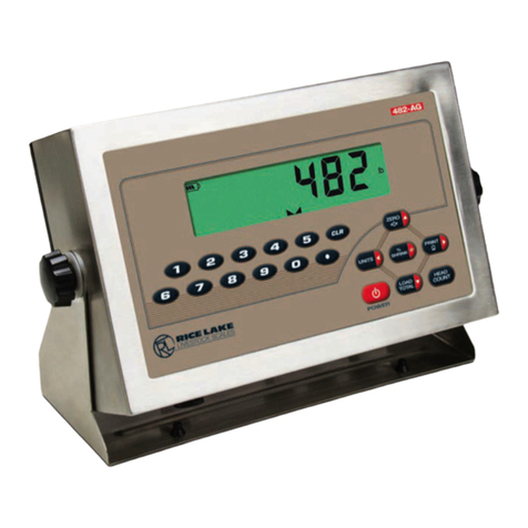
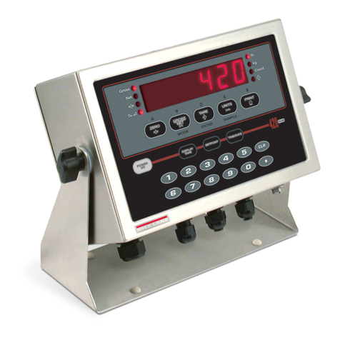
The 320IS Plus is a single-channel digital weight
indicator designed and approved to operate as an
intrinsically safe system in a wide variety of scale and
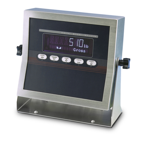
weighing applications. The indicator is housed in a
NEMA 4X/IP66-rated stainless steel sealed case. The
standard unit is equipped with a tilt stand base for
tabletop or wall mounting applications. The indicator
front panel consists of a large (0.8 in, 20 mm,
16-segment), six-digit LED display, 24-button keypad
and eight LED annunciators. Features include:
• Drives up to four 350Ω or eight 700Ωload
cells
• Supports four- and six-wire load cell
connections (six-wire remote sense
recommended)
• Full-duplex fiber optic interface to attach an
external I/O board located in the safe area
The 320IS Plus is NTEP-certified and pending
Measurement Canada approval for Classes I, II and III
at 10,000 divisions. See See Section 9.10 on page 68
for detailed specifications.
Available with optional I/O Module (PN 72721):
• Four configurable digital inputs
• Four digitally-controlled single pole single
throw-normally open non-latching relay
contact outputs
• Electronic data processing (EDP) port
communications at up to 38400 bps for full
duplex RS-232/RS-422/RS-485 and Current
loop
• Printer port communications at up to 38400
bps for full duplex RS-232/RS-422/RS-485
and Current loop
• Two 16–bit analog output channels provide
±10V or ±5V, 0-5V or 0-10V, and 4-20 mA
tracking of gross or net weight values
1.1 Factory Mutual Approval
The 320IS Plus is Factory Mutual (FM) Entity
approved for:
• Classes I, II, and III
• Divisions 1 and 2
• Groups A, B, C, D, E, F and G
• T-rating T4
Only devices that have FM Entity Approval with
proper entity parameters may be used unless
specifically listed in this manual or control drawing
PN 72717 as part of the Rice Lake Factory Mutual
systems approval. Failure to comply with this voids
the FM approval.
The classification of hazardous materials are different
in the US and European standards. Because of this, the
safety class of the 320IS Plus is declared in the
following regulations:
• US standards: Class I, II, III, DIV1, Groups
A-G
Substitution of components may impair
intrinsic safety.
To prevent ignition of flammable or
combustible atmospheres, disconnect
power before servicing.
Warning
Warning
