manuals.online logo
Brands
  1. Home
  2. •
  3. Brands
  4. •
  5. Rice Lake
  6. •
  7. Accessories
  8. •
  9. Rice Lake IQ plus 590-DC Parts list manual

Rice Lake IQ plus 590-DC Parts list manual

Other Rice Lake Accessories manuals

Rice Lake 120 User manual

Rice Lake

Rice Lake 120 User manual

Rice Lake IQ plus 710 User manual

Rice Lake

Rice Lake IQ plus 710 User manual

Rice Lake iRite 920i User manual

Rice Lake

Rice Lake iRite 920i User manual

Rice Lake 520 User manual

Rice Lake

Rice Lake 520 User manual

Rice Lake RailBoss 1280 Enterprise iRite User manual

Rice Lake

Rice Lake RailBoss 1280 Enterprise iRite User manual

Rice Lake IQ plus 355 User manual

Rice Lake

Rice Lake IQ plus 355 User manual

Rice Lake SCT-2200 User manual

Rice Lake

Rice Lake SCT-2200 User manual

Rice Lake CLS420 User manual

Rice Lake

Rice Lake CLS420 User manual

Rice Lake EZ Mount User manual

Rice Lake

Rice Lake EZ Mount User manual

Rice Lake MSI-8000 User manual

Rice Lake

Rice Lake MSI-8000 User manual

Rice Lake IQ plus 350 User manual

Rice Lake

Rice Lake IQ plus 350 User manual

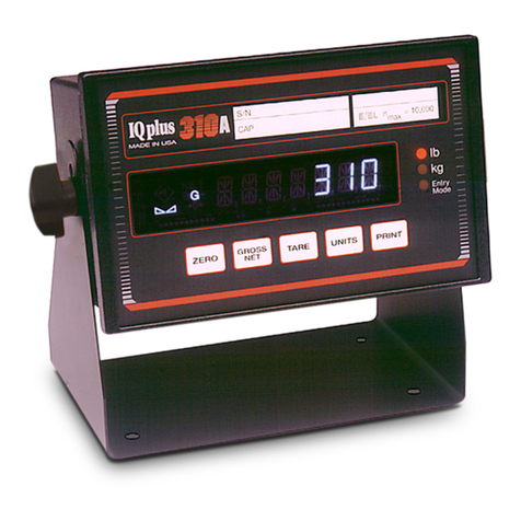
Rice Lake IQ plus 310A User manual

Rice Lake

Rice Lake IQ plus 310A User manual

Rice Lake 482-AG User manual

Rice Lake

Rice Lake 482-AG User manual

Rice Lake iRite 920i User manual

Rice Lake

Rice Lake iRite 920i User manual

Rice Lake MSI-8000HD User manual

Rice Lake

Rice Lake MSI-8000HD User manual

Rice Lake FlexWeigh System 101 User manual

Rice Lake

Rice Lake FlexWeigh System 101 User manual

Rice Lake IQ plus 310A User manual

Rice Lake

Rice Lake IQ plus 310A User manual

Rice Lake 380 Synergy User manual

Rice Lake

Rice Lake 380 Synergy User manual

Rice Lake REVOLUTION 682 Synergy Plus User manual

Rice Lake

Rice Lake REVOLUTION 682 Synergy Plus User manual

Rice Lake RL1800 Series User manual

Rice Lake

Rice Lake RL1800 Series User manual

Rice Lake IQ plus 390-DC Parts list manual

Rice Lake

Rice Lake IQ plus 390-DC Parts list manual

Rice Lake iRite 920i User manual

Rice Lake

Rice Lake iRite 920i User manual

Rice Lake RL1800 Series User manual

Rice Lake

Rice Lake RL1800 Series User manual

Rice Lake RL50210 TA User manual

Rice Lake

Rice Lake RL50210 TA User manual

Popular Accessories manuals by other brands

Quincy lab 140AE-1 operating manual

Quincy lab

Quincy lab 140AE-1 operating manual

HomePro ZIR000 user manual

HomePro

HomePro ZIR000 user manual

DOL 20SCR Technical user guide

DOL

DOL 20SCR Technical user guide

RAB Smart Task installation manual

RAB

RAB Smart Task installation manual

Kemppi KMS 300 quick guide

Kemppi

Kemppi KMS 300 quick guide

Stearns 57,500 Series Installation and service instructions

Stearns

Stearns 57,500 Series Installation and service instructions

iGuzzini TWILIGHT COPENAGHEN manual

iGuzzini

iGuzzini TWILIGHT COPENAGHEN manual

Adelaide Annexe & Canvas Avan Deluxe installation guide

Adelaide Annexe & Canvas

Adelaide Annexe & Canvas Avan Deluxe installation guide

OHAUS 5000 instruction manual

OHAUS

OHAUS 5000 instruction manual

HOME8 WLS1300 quick start guide

HOME8

HOME8 WLS1300 quick start guide

MAXBOTIX MaxSonar quick start guide

MAXBOTIX

MAXBOTIX MaxSonar quick start guide

ioSmart iSmart56 Installation and user guide

ioSmart

ioSmart iSmart56 Installation and user guide

Focusrite Scarlett 18i8 user guide

Focusrite

Focusrite Scarlett 18i8 user guide

Velleman ED38105 user manual

Velleman

Velleman ED38105 user manual

JumpSport SkyBounce user manual

JumpSport

JumpSport SkyBounce user manual

Prima-Temp PRIYA Instructions for use

Prima-Temp

Prima-Temp PRIYA Instructions for use

Tefcold BC85I-BC85I W user manual

Tefcold

Tefcold BC85I-BC85I W user manual

Vaisala WMS302 user guide

Vaisala

Vaisala WMS302 user guide

manuals.online logo
manuals.online logoBrands
  • About & Mission
  • Contact us
  • Privacy Policy
  • Terms and Conditions

Copyright 2025 Manuals.Online. All Rights Reserved.

May 2002
IQ plus
®
590-DC Digital Weight Indicator
Operator Card
Do not open the indicator enclosure!
Refer all repairs and modifications to
your distributor or service technician.
This
Operator Card
describes the IQ plus 590-DC LCD display, weighing and counting operations, and
procedures for battery replacement and AC adapter use.
LCD Display and Annunciators
The IQ plus 590-DC display uses a set of LCD
annunciators to provide additional information about
the value being displayed. The illustration below
shows these annunciators and their meanings.
G
The displayed weight is a gross weight.
N
The displayed weight is a net weight.
Scale is at standstill or within the specified motion
band. Some operations, including zero, tare, and
printing functions, can only be done when the
standstill symbol is shown.
Center of zero. Gross weight is within 0.25
graduations of zero. This annunciator lights when
the scale is zeroed.
Indicates that a tare has been entered. The tare
value can be entered by pressing the
TARE
key on
the keypad or by sending the KTARE EDP
command.
Indicates that the battery charge is low.
lb, kg, PC
Three arrow annunciators on the right side of the
LCD display indicate the units associated with the
displayed value. The bottom arrow annunciator
(PC) is lit when the indicator is in piece count
mode. The top and middle arrows, labeled lb and
kg, show primary and secondary units, as
described below:
•If the displayed weight is in pounds, the top
arrow (lb) is lit; if kilograms, the middle
arrow (kg) is lit.
•If the primary unit of weight is pounds, the
middle (kg) arrow is lit for secondary units—
or, if the primary unit is kilograms, the top
(lb) arrow is lit for secondary units, unless the
secondary unit of weight is the same as the
primary unit.
•If neither primary nor secondary units are
pounds or kilograms, the top arrow is used as
a primary units annunciator and the middle
arrow is used as the secondary units
annunciator.
A set of replacement overlay decals is included in
the parts kit for units other than pounds and
kilograms.
Warning
Gross mode
Net modeStandstill
Center of zero
Tare in system
Low battery
lb
kg
PC
Displayed units
Secondary
Primary
Piece count mode
2
IQ plus 590-DC Operator Card
Weighing Operations
The illustration below shows the IQ plus 590-DC keypad and normal mode key functions.
Basic IQ plus 590-DC weighing operations are
summarized below:
Toggle Gross/Net/Piece Count Mode
Press the
GROSS/NET
key to switch the display mode
between gross, net, and piece count modes. If a tare
value has been entered or acquired, the net value is the
gross weight minus the tare. If access to piece count
mode is disabled, pressing the
GROSS/NET
key
switches between gross and net modes only.
Gross mode is shown by the
G
annunciator; net mode
is shown by the
N
annunciator. Piece count mode is
shown by the LCD annunciator adjacent to the
PC
at
the right edge of the display.
Toggle Units
Press the
UNITS
key to switch between primary and
secondary units. The units annunciator arrow on the
right side of the LCD display points to the units
identifier.
Zero Scale
1. In gross mode, remove all weight from the
scale and wait for the standstill annunciator
().
2. Press the
ZERO
key. The center of zero
()annunciator lights to indicate the
scale is zeroed.
Acquire Tare
1. Place container on scale and wait for the
standstill annunciator ( ).
2. Press the
TARE
key to acquire the tare weight
of the container.
3. Net weight is displayed and the
annunciator lights to show the tare value was
acquired.
Enter Tare (Keyed Tare)
1. Use the numeric keypad to enter the tare
value, then press the
TARE
key.
2. Net weight is displayed and the
annunciator lit to show the tare value was
entered.
Remove Stored Tare Value
1. Remove all weight from the scale and wait for
the standstill annunciator ( ).
2. Press the
TARE
key. The annunciator goes
off, indicating the tare value has been
removed.
Indicators with the REGULA parameter set to
NONE or NTEP can clear a stored tare value
using the following procedure:
1. Press
DISPLAY TARE
to show the stored tare
value.
2. Press the
CLEAR
key twice to remove the
stored tare.
Print Ticket
1. Wait for the standstill annunciator ( ).
2. Press the
PRINT
key to send weight data to
the serial port.
T
4
90
8
5
2
76
3
CLEAR
DISPLAY
TARE
ZERO GROSS
NET TARE UNITS PRINT
B/N
Units
POWER
ENTER SAMPLEMODE PRINT
I/O
Switch between
primary and
secondary units
Send data to
serial port
Set gross weight
to zero
Switch between
gross, net, and
piece count mode
Acquire tare
NORMAL MODE KEY FUNCTIONS
Display current
tare weight Power on/off
T
IQ plus 590-DC Operator Card
3
Counting Operations
The illustration below shows the IQ plus 590-DC keypad and piece count mode key functions.
NOTE:
Legal-for-trade applications require product to be sold by weight rather than an equivalent parts
count. Operator access to piece count mode is disabled when the indicator is shipped from the factory. To
use piece count mode, access must be enabled when the indicator is configured.
Piece count mode is entered by pressing the
MODE
(
GROSS/NET
) key from normal weighing mode. In
count display mode, the display shows the number of
parts rather than weight, the arrow annunciator at the
right side of the LCD display points to piece count
(PC), and pressing the
PRINT
key sends the CFMT
print format data string to the serial port.
IQ plus 590-DC counting operations are summarized
below:
Acquire Parts Sample
1. Place empty parts container on scale. Wait for
the standstill annunciator ( ), then press
TARE
to acquire the tare weight of the
container.
2. Press
MODE
to enter piece count mode.
3. Press the
SAMPLE
(
UNITS
) key to enter
sample acquisition mode.
4. The indicator display shows the message
Addnnn
, where
nnn
is the sample quantity to
be placed on the scale. You can do one of the
following:
• Add the number of parts shown.
•Choose a different sample size. Press the
SAMPLE
key to scroll through the
selectable sample quantities (5, 10, 20,
50, 100) or use the numeric keypad to
specify a custom sample size.
•Specify a known piece weight. Press the
SAMPLE
key to scroll through the
selectable sample quantities until the
PC
WGT
prompt is shown. Use the numeric
keypad to enter the piece weight.
5. Once the sample quantity is on the scale,
press
ENTER
to calibrate the indicator for
counting the new parts. If a sample size was
specified, the indicator display shows the
message
–CNT–
as it acquires the sample
weight, then switches to count display mode
and shows the part quantity. If a known piece
weight was specified, the display switches to
count display mode immediately.
Display Part Weight
To view gross and net weight of parts, press
MODE
to switch from count display mode to
normal weighing mode. To view the current piece
weight while in count mode, press the
DISPLAY
TARE
key.
Print Ticket
1. Wait for the standstill annunciator ( ).
2. Press the
PRINT
key to send piece count data
to the serial port.
T
4
90
8
5
2
76
3
CLEAR
DISPLAY
TARE
ZERO GROSS
NET TARE UNITS PRINT
B/N Units
POWER
ENTER SAMPLEMODE PRINT
I/O
New sample / change
sample quantity
Send data to
serial port
(CFMT format)
Not used
Switch between
gross, net, and
piece count mode
Acquire tare /
acquire sample
COUNTING MODE KEY FUNCTIONS
Display current
piece weight Power on/off
T
4
IQ plus 590-DC Operator Card
Battery Installation
To install or replace batteries, do the following:
1. Remove the four thumbscrews that hold the
battery cover to the enclosure backplate.
2. Install six alkaline C-cell batteries as shown
in Figure 1.
3. Replace the battery cover and reinstall
thumbscrews. Torque thumbscrews to 15 in-lb
(1.7 N-m).
NOTE: A grounding screw is provided on the indicator
backplate for connecting a grouding wire (see Figure 3 on
page 4).
Figure 1. Battery Installation
Using the AC Adapter
The AC adapter can be used to provide power to the
indicator if battery power is low and AC power is
available. Use only the adapter supplied with the
indicator.
To use the AC adapter, do the following:
1. Remove the top screw from the AC adapter
port cover.
2. Loosen the bottom screw, then rotate the port
cover to expose the AC adapter port (see
Figure 2).
3. Reinstall the top screw in the backplate.
4. Plug AC adapter from power outlet to the
indicator adapter port.
The IQ plus 590-DC enclosure cannot
be rated for NEMA 4X/IP66 applications
with the AC adapter port cover open.
Do not use the AC adapter in washdown environments.
Figure 2. AC Adapter Port Cover
When not using the AC adapter, close the adapter port
cover and reinstall all backplate screws. Use the
torque pattern shown in Figure 3 to prevent distorting
the backplate gasket. Torque screws to 15 in-lb (1.7
N-m).
Figure 3. Enclosure Backplate
+
+––
+–
+
+––
+–
Caution
1
3
4
56
2
7
Torque backplate screws
to 15 in-lb (1.7 N-m)
Torque
pattern
8
Grounding
Screw