Richmond Powertrax User manual

INSTALLATION GUIDE
TM


Installation Guide
Contents Page
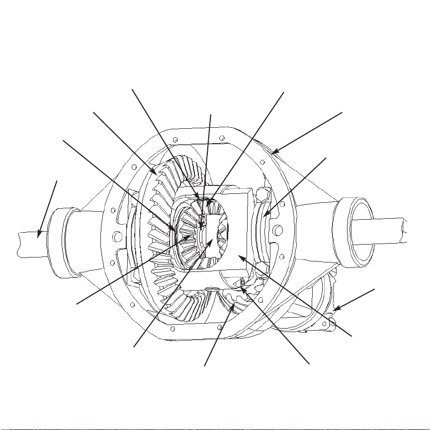
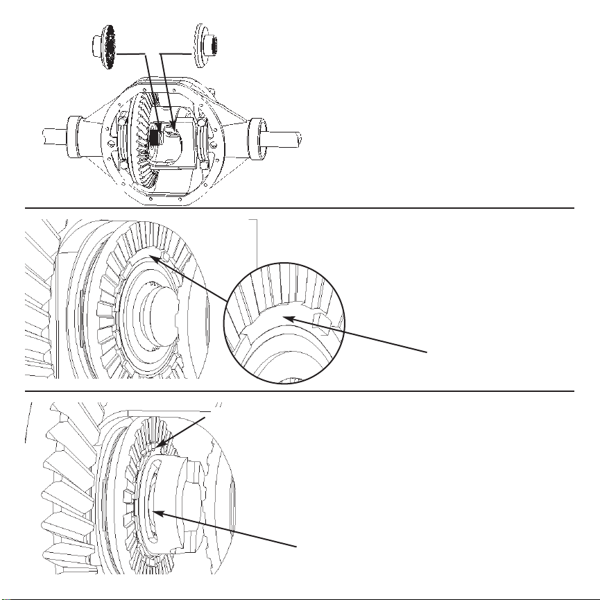
Open Differential Part Identification & Terminology ......... 2
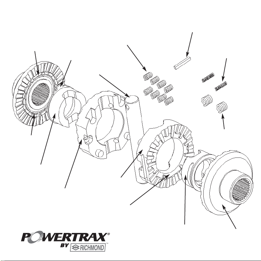
Powertrax No-Slip Differential Exploded View .................. 3
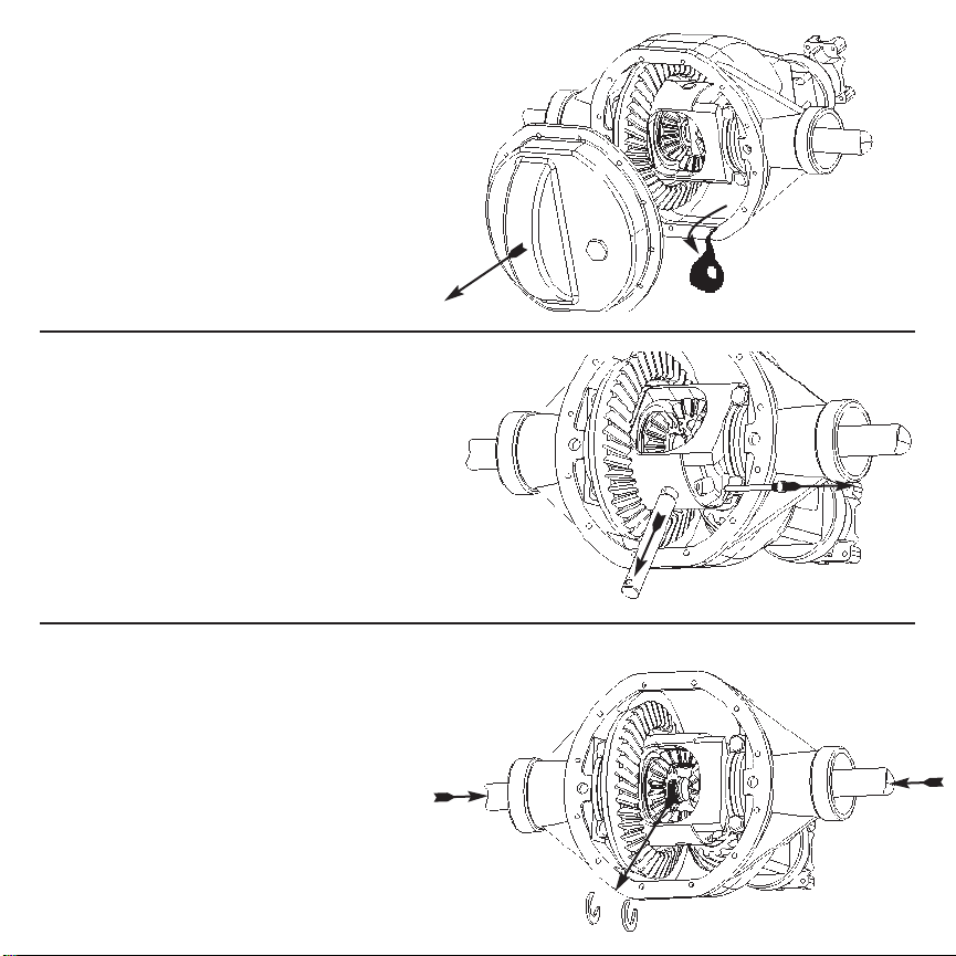
Vehicle Preparation for Installation (steps 1 to 5) ............. 4
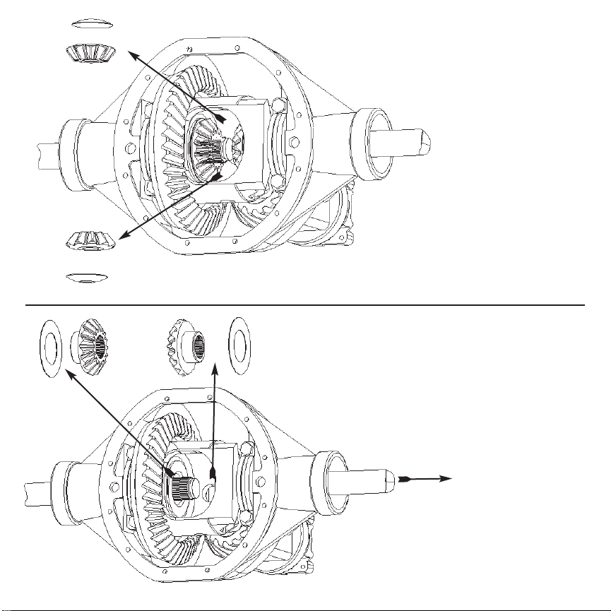
Removal of Open Differential Parts (steps 6 to 10) ........... 5
Preparation of Parts to be Installed (steps 11 to 13) ......... 7
Assembly (steps 14 to 40) .............................................. 8
Verification of Proper Assembly Test (steps 41 to 45) ....... 17
Finish Installation (steps 46 to 50) .................................. 18
Thoroughly read User Manual.
Traction output and resulting handling characteristics of your vehicle will be modified by installation.
Drive carefully and use caution under all on-road and off-road conditions.

Axle Housing
Axle Shaft (2)
Ring Gear
Side Gear (2)
Differential Case
Bearing Cap (2)
Pinion Gear
Thrust Washer (2)
Pinion Shaft
Spider Gear (2)
Pinion Shaft
Retaining Bolt or Roll Pin
C-Clip (2)
2
Spider Gear Washer (2)
Yoke
OPEN DIFFERENTIAL
PART IDENTIFICATION/TERMINOLOGY

Pinion Shaft
Driver
(Slotted)
Synchro
Ring
Coupler
3
Paddle
Paddle Opening
in Synchro
Driver
(Non-Slotted)
Saddle Springs (8)
Active Spacer
Paddle Opening in Driver
(Missing Extended Tooth)
Active Spacer
Inner Springs (2)
Outer Springs (2)
EXPLODED VIEW Check Block

4
1. Put transmission in gear (or park), and
turn off engine.
2. Set parking brake.
3. Safeguard the vehicle from rolling.
4. Safely raise vehicle and
apply jack stands.
5. Put transmission in neutral and release parking brake.

5
6. Remove Differential cover and
drain fluid. Clean the diff cover and
housing sealing surface.
7. Expose pinion shaft; remove
retaining bolt/roll pin and shaft.
8. Push both axles inward and
remove both c-clips. Remove o-
rings from c-clip grooves on axle
shafts if present.
Note: It may be necessary
to remove wheels and disc
brake calipers.

6
9. Remove both spider gears and
their thrust washers.
10. Pull passenger side axle shaft
out approximately 6”. Remove side
gears and thrust washers.

11. Verify gaps in coupler
teeth are aligned with gaps in
synchro ring. Place coupler in
a vise and use an active spacer
to align them if necessary.
13. Apply wheel bearing grease to
saddle springs and seat in holes.
12. Apply wheel bearing grease to
driver teeth and spacer.
7

14. Install couplers inside differential
case, ring gear side first.
12
8
15. Make sure paddle opening
(widest gap) in ring gear side syn-
chro ring is facing up.
Paddle Opening
16. Place an active spacer onto the
ring gear side coupler as shown.
Make sure spacer paddle is seated
in the paddle opening of the synchro
ring and c-clip slot is facing out
towards you.
C-Clip Slot
Spacer Paddle

17. Make sure c-clip groove on ring
gear side axle shaft is aligned with
the c-clip slot in the spacer and
insert a c-clip onto the axle shaft.
Pull out on wheel to seat the c-clip
inside the spacer.
9
18. Rotate ring gear side wheel 1/4
turn back so that the spacer paddle
and the opening in the synchro ring
is facing out towards you.
19. Insert the non-slotted driver as
shown, making sure the paddle
opening in driver (missing extended
tooth) is facing out towards you.
Spacer Paddle

20. Press driver down onto coupler.
Driver teeth should be fully engaged
all the way around.
10
21. Insert the second active spacer
into the slotted driver. Seat the
spacer paddle at the paddle open-
ing in driver (missing extended
tooth).
22. Verify paddle opening (widest
gap) in other synchro ring is facing
away from you.
Paddle Opening

23. Install slotted driver/spacer mak-
ing sure the spacer paddle is point-
ing away from you toward the differ-
ential.
11
24. Verify spacer paddle is aligned
with the paddle opening in synchro
ring and press down on driver/spac-
er to seat on coupler; driver teeth
should be fully engaged all the way
around.
25. Wedge both drivers in engage-
ment with couplers. Rotate driver’s
side wheel forward 1/4 turn to
reveal spring slot.
spring slot

26. Place the two inner springs
inside the two outer springs.
27. Compress inner spring and
install spring assembly into spring
slot.
28. Visually inspect notches in
spring slot to make sure inner
spring is fully seated.
12
check spring

29. Keeping both drivers wedged in
engagement with couplers, rotate
driver’s side wheel forward 1/2 turn
to reveal spring slot on other side.
30. Compress inner spring and
install the second spring assembly
into the second spring slot.
31. Visually inspect notches in
spring slot to make sure inner
spring is fully seated.
13
check spring

14
c-clip slot 34. Making sure drivers stay
engaged with couplers, carefully
rotate wheels until c-clip slot is
accessible. Verify c-clip groove on
axle is accessible through c-clip
slots on driver and spacer.
33. Push passenger side axle shaft
inward through coupler as far as it
will go.
32. Check the gap between
drivers using check block. The
narrow side of the block should
fit between the drivers, but the
wider side should not fit.
Go No Go
If gap is incorrect, STOP and call
Powertrax Technical Support at
864-843-9275. There may be a
problem with your differential case.

15 pinion shaft opening
35. Insert 2nd c-clip through c-clip
slot in driver onto axle shaft; pull
axle shaft out to seat c-clip.
36. Making sure drivers stay
engaged with couplers, carefully
rotate both wheels backwards 1/4
turn to expose pinion shaft opening.
37. Feel through pinion shaft open-
ing and verify both spacers and
drivers are fully seated onto cou-
plers. Verify all 8 saddle springs
are fully seated in holes.
saddle springs
pinion shaft opening

16
40. Insert retaining bolt/roll-pin into
case/shaft. Tighten retaining bolt
firmly.
39. Using the retaining bolt/roll-pin
as a handle, insert the shaft into the
differential. Press hard while twist-
ing to pass shaft by springs.
38. Keeping couplers and drivers
stationary, rotate case 1/4 turn for-
ward to align pinion shaft opening
with driver saddles.

41. Put transmission in gear (or park).
HOLD
43. Passenger side wheel
should not be able to rotate in
the same direction.
45.Repeat the test for both wheels in both
directions.
42. Turn driver’s side
wheel forward and hold
against driveline for steps
43 & 44.
17
HOLD
HOLD
44. After sharply turning the
passenger side wheel in the
opposite direction (to
disengage the unit), the
wheel should rotate freely.

18
46. Install differential cover with gasket sealant.
48. Set parking brake.
49. Be sure transmission is in
gear or park.
50. Remove jack stands, lower vehicle, then remove
blocks.
47. Add Richmond Synthetic
Gear Oil (75W-140) available
at your Authorized Richmond
Distributor.
Table of contents