GTR130 Bluetooth Receiver Manual Rev 1
How to pair the USB transmitter to the receiver:
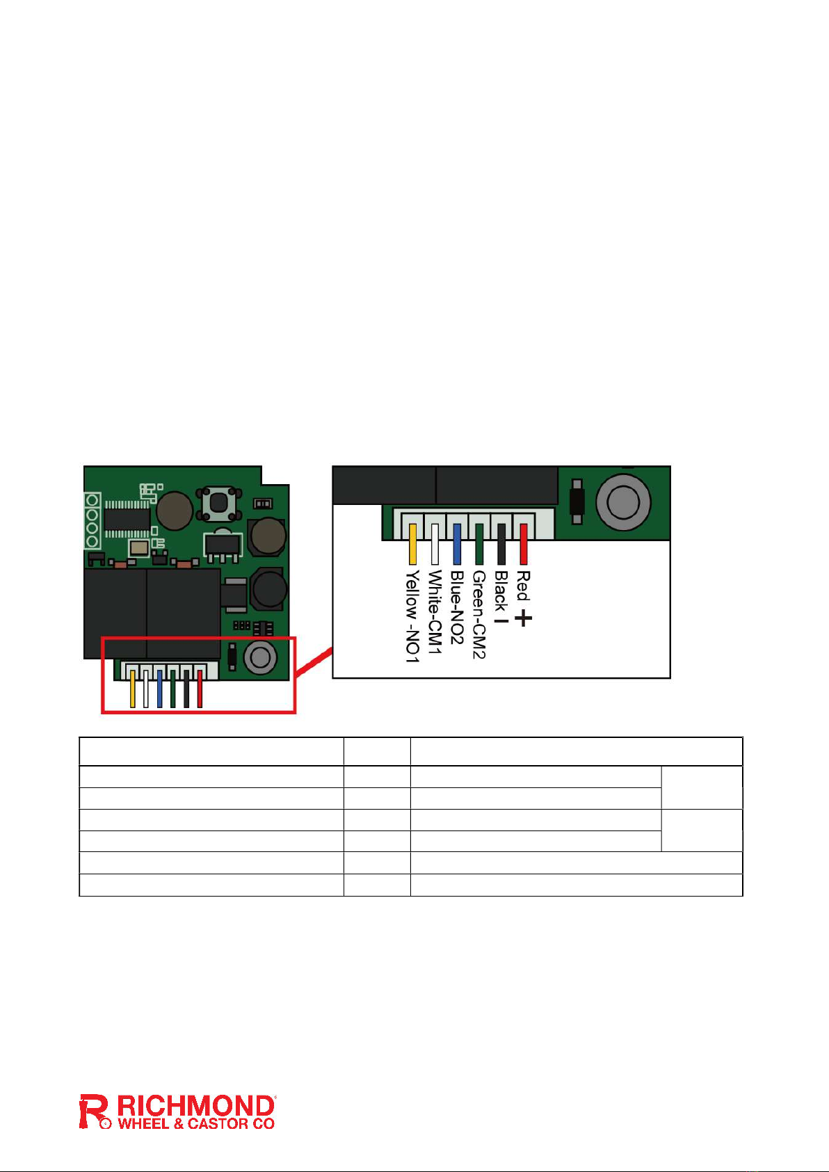
1. Install the Transmitter: Connect the USB transmitter to your vehicle USB port or other power source. A phone charger wall plug can be used to temporarily power the Transmitter. 2. Install the Receiver: Install the Receiver to your gate or garage motor using the wiring instructions below. Press the P1 button once on the receiver. The LED will flash twice to indicate pairing of the Transmitter and Receiver. Press the button again to exit learning mode. If the LED doesn’t flash and pairing fails, check your USB Transmitter is correctly powered and within range of the Receiver and pair again. 3. Delete all paired Transmitters: Hold the P1 button for 5 seconds until the LED flashes five times. After 5 flashes all saved transmitters will be deleted and the button can be released. Wiring Diagram Receiver Wire Colour Label Function
Yellow NO1 Connect to the OPEN terminal. Channel 1
White CM1 Connect to the COM terminal.
Blue NO2 Connect to the CLOSE terminal. Channel 2
Green CM2 Connect to the COM terminal.
Black − Connect to NEGATIVE voltage or GND terminal.
Red + Connect to 12-24 volt AC or Positive DC terminal.
How to connect the receiver you your gate PC board
- Channel 1 (Yellow/White) triggers an opening when the vehicle comes into range. - Channel 2 (Blue/Green) triggers a closing after 10 seconds when the vehicle is turned off or when the vehicle leaves the 10-metre operating range. - Channel 2 is optional if your gate/garage motor has auto-close activated. If auto-close is being used, channel 2 does not need to be connected.


