Richter MNK-B Series User manual

INSTALLATION AND OPERATING MANUAL
Translation of the original manual
Keep for future use!
This operating manual must be strictly observed before
transport, installation, operation and maintenance
Subject to change without notice.
Reproduction is generally permitted with indication of the source.
© Richter Chemie-Technik GmbH
9230-056-en Revision 14 Edition 06/2016
Series MNK-B
Sealless Chemical
Magnetic Drive Pump
Close-coupled design
Size 25-25-100

Series MNK-B, size 25-25-100 Page 2
9230-056-en Revision 14
TM 9542 Edition 06/2016
List of Contents
List of Contents.................................................2
Relevant documents.........................................3
1Technical data .............................................3
1.1 Tightening torques .......................................... 4
1.2 Type plate, dry-running, ATEX-and housing
markings........................................................... 4
1.3 Spare parts....................................................... 4
2Notes on safety............................................5
2.1 Intended use .................................................... 5
2.2 For the customer/operator ............................. 6
2.3 For maintenance.............................................. 6
2.4 Conversion work and production of spare
parts by the customer..................................... 6
2.5 Improper operation.......................................... 6
2.6 Special requirements for explosion protection
....................................................................... 6
2.6.1 Filling the unit........................................................6
2.6.2 Special operating conditions ...............................7
2.6.3 Chargeable liquids................................................7
2.6.4 Identification..........................................................7
2.6.5 Check of the direction of rotation........................7
2.6.6 Mode of operation of the pump...........................7
2.6.7 Temperature limits................................................8
2.6.8 Maintenance..........................................................8
2.6.9 Electric peripheral equipment..............................8
3Transport, storage and disposal...............9
3.1 Return consignments...................................... 9
3.2 Disposal............................................................ 9
4Product description ....................................9
5Installation.................................................. 10
5.1 Safety regulations.......................................... 10
5.2 Installation of pump/unit ............................... 10
5.3 Alignment of pump - motor........................... 10
5.4 Piping.............................................................. 10
5.4.1 Nominal size........................................................10
5.4.2 Nozzle loads........................................................10
5.4.3 Suction line..........................................................11
5.4.4 Supply lines.........................................................11
5.4.5 Discharge line......................................................11
5.4.6 Venting and evacuating .....................................11
5.5 Pipe fittings..................................................... 11
5.6 Monitoring facilities........................................ 11
5.7 Drive................................................................ 11
5.8 Electric connection........................................ 12
6Commissioning/Shutdown.......................13
6.1 Initial commissioning..................................... 13
6.1.1 Filling the pump housing....................................13
6.1.2 Start-up ................................................................13
6.2 Operating limits.............................................. 13
6.2.1 Abrasive media...................................................13
6.2.2 Min./max. flow rate .............................................13
6.3 Shutdown........................................................ 13
6.4 Restarting ....................................................... 14
6.5 Improper operation and their consequences
(examples)...................................................... 14
7Maintenance...............................................15
7.1 Screw connections of the housing.............. 15
7.2 Motor............................................................... 15
7.3 Cleaning.......................................................... 15
7.4 Stand-by pumps ............................................ 15
7.5 Notes on dismantling .................................... 15
7.5.1 Protective clothing..............................................15
7.5.2 Magnetic fields....................................................15
7.6 Dismantling..................................................... 16
7.6.1 Dismantling the slide-in unit..............................16
7.6.2 Dismantling of drive unit.....................................16
7.7 Notes on assembly........................................ 16
7.8 Assembly........................................................ 16
7.8.1 Assembly of drive unit........................................16
7.8.2 Assembly of slide-in unit....................................16
7.8.3 Trial assembly of impeller and bearing bush...16
7.8.4 Determine thicknesses S1and S2of the distance
washers 551........................................................17
7.8.5 Final assembly....................................................17
7.9 Tests................................................................ 17
8Faults ..........................................................18
9Sectional drawing MNK-B, size 25-25-100
(with back plate mades of stainless steel
1.4301/PFA).................................................19

Series MNK-B, size 25-25-100 Page 3
9230-056-en Revision 14
TM 9542 Edition 06/2016
Relevant documents
Data sheet
Works certificate
Sectional drawing MNK-B Size 25-25-100
Back plate CFK 9230-00-0013
Anchored back plate 9230-00-3024
Dimensional drawing 9230-00-3025
Outline drawing
Performance curves
Spare parts list
Operating manual and declaration of conformity
motor
Appendix to the operating instructions
Operational limits 9200-00-0030
Declaration of conformity with ATEX
Declaration of conformity without ATEX
Form for Safety Information Concerning the
Contamination QM 0912-16-2001_en
On request:
Magnetic drive data Richter TIS 0543-03-0001
Publication: "Centrifugal Pump Operation without
NSPH Problems"
Publication "Safe Operation of Magnetic Drive
Pumps“
1 Technical data
Manufacturer :
Richter Chemie-Technik GmbH
Otto-Schott-Str. 2
D-47906 Kempen
Designation :
Single-stage, plastic-lined, magnetic drive chemical
centrifugal pump, series MNK-B, close-coupled
design, size 25-25-100
Heavy-duty horizontal design, sealless, with back
plate made of stainless steel 1.4301/PFA or
heavy-duty horizontal design, sealless, eddy-current-
free back plate made of CFRP/PTFE
Flange connecting dimensions:
DIN EN 1092-2, type B (ISO 7005-2, type B) PN 16
or flanges drilled to ASME 16.5, Class 150
ATEX Directive 2014/34/EU
Machine Directive 2006/42/EC
Materials :
Pressurized parts:
ductile cast iron EN-JS 1049
Wetted parts:
PFA, PTFE, PE-UHMW, PP, PFA-P, anti-static lining
(PFA/PTFE conductive) SSiC, FKM/FFKM,
see also data sheet
Flow rate : up to 6 m3/h (at 2900-1/min)
Delivery head : up to 14,6 m FS (at 2900-1/min)
Housing discharge pressure : max. 10 bar
Back plate
made of stainless steel 1.4301/PFA 10 bar
not certified to ATEX T3-T6
made of CFRP/PTFE 6 bar
Temperature range : - 60 °C to + 150 °C
Note: Consult the manufacturer for higher pressures
and lower or higher temperatures.
Temperature classes: see Section 2.6.7
Noise pressure level : LWA = ≤ 70 dB acc. to DIN
EN ISO 9614-2
Admissible ambient conditions for pumps acc. to
directive 2014/34/EU (ATEX) :
Ambient temperature range: - 20 °C to + 40 °C
(higher temperature after consulting the manufacturer)
Ambient pressure range: 0,8 barabs to 1,1 barabs
Sizes : 25-25-100
Weight : See data sheet
Dimensions : See installation drawing
Design of the motors to be used :
If the motor is supplied or mounted by the customer,
the following data must be observed:
Design B14
Size 71, 80
Flange Ǿ 120 mm
Front-end tapped bore to DIN 332-2 design D.
The motors must be provided with fixed bearings on
the drive side.

Series MNK-B, size 25-25-100 Page 4
9230-056-en Revision 14
TM 9542 Edition 06/2016
1.1 Tightening torques
Screws greased, tighten in diametrically opposite
sequence
Housing screws 901/3
Size
No. x size
Nm
25-25-100
10 x M 8
10
Pipe screws, flanges to DIN/ISO
DN
No. x size
Nm
25
4 x M 12
10
Pipe screws, DIN/ISO flanges drilled to ASME
DN
[mm] [inch]
No. x size
ASME
Nm
in-lbs
25
1“
4 x ½“
8
70
1.2 Type plate, dry-running, ATEX-
and housing markings
The stainless steel type plate is firmly riveted to the
housing:
If the operator attaches his identification, it must be
ensured that the pump matches the application in
question.
Example of type plate:
Dry-running:
ATEX marking:
Housing identification:
The following are visible on the housing according to
DIN EN 19:
Nominal size
Rated pressure
Housing material
Manufacturer's identification
Melt number/Foundry identification
Foundry date
1.3 Spare parts
Spare parts for two years of continuous operation in
accordance with DIN 24296 and in consultation with
the manufacturer.

Series MNK-B, size 25-25-100 Page 5
9230-056-en Revision 14
TM 9542 Edition 06/2016
2 Notes on safety
This operating manual contains fundamental
information which is to be observed during installation,
operation and maintenance.
It must be read before installation and
commissioning!
This operating manual must always be available at the
place of use of the machine/plant.
In addition to the general notes on safety under the
main heading “Safety”, special notes on safety are
included at other points and must be observed.
Installation, operation and maintenance are to be
performed by qualified staff.
The area of responsibility, authority and supervision of
the staff must be exactly regulated by the customer.
If the staff does not have the necessary expertise,
they are to be trained and instructed.
If necessary, this can be provided by the
manufacturer/supplier on behalf of the machine
operator.
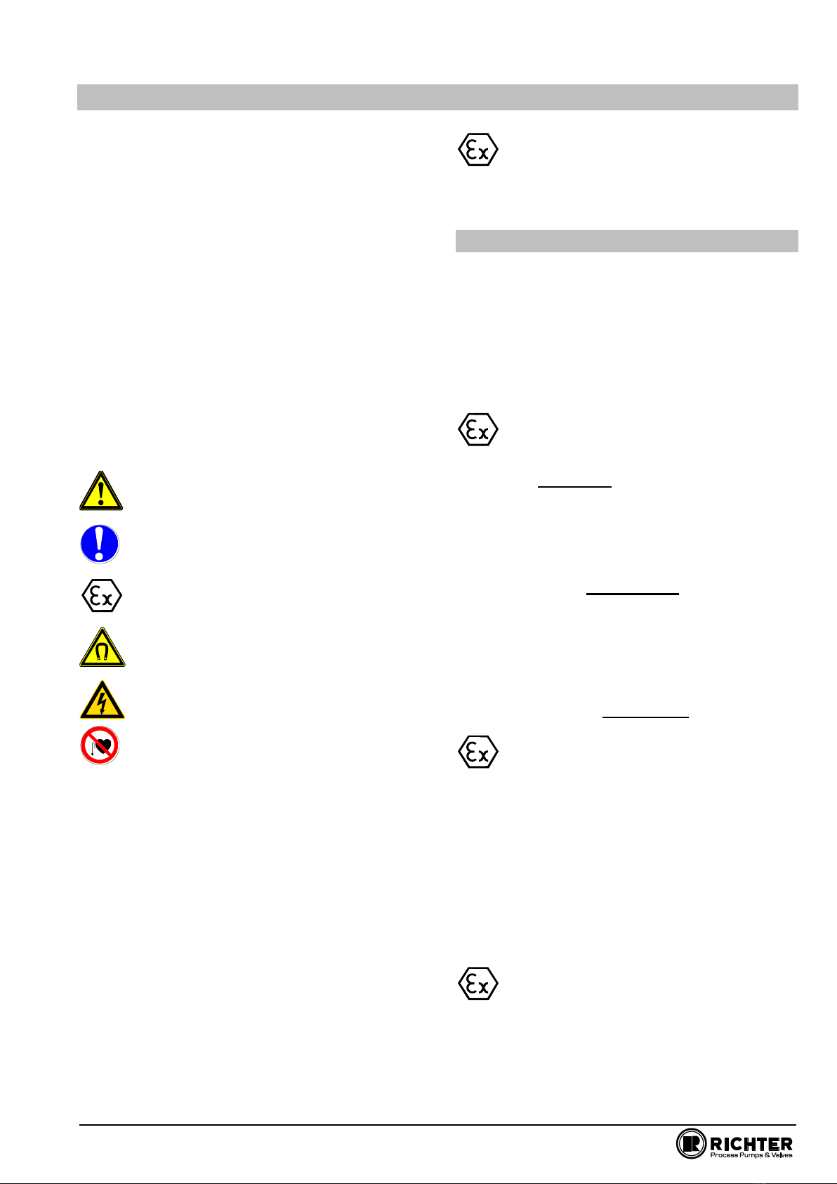
General hazard symbol! People may be put
at risk.
Safety symbol! The pump and its function
may be put at risk if this safety symbol is not
observed.
EU marking! Explosion-protected equipment
must be identified for work in potentially
explosive areas.
Warning of a magnetic field!
Warning of electric power!
This warning sign must be used if people
with a pacemaker are at risk, e.g. from a
strong magnetic field.
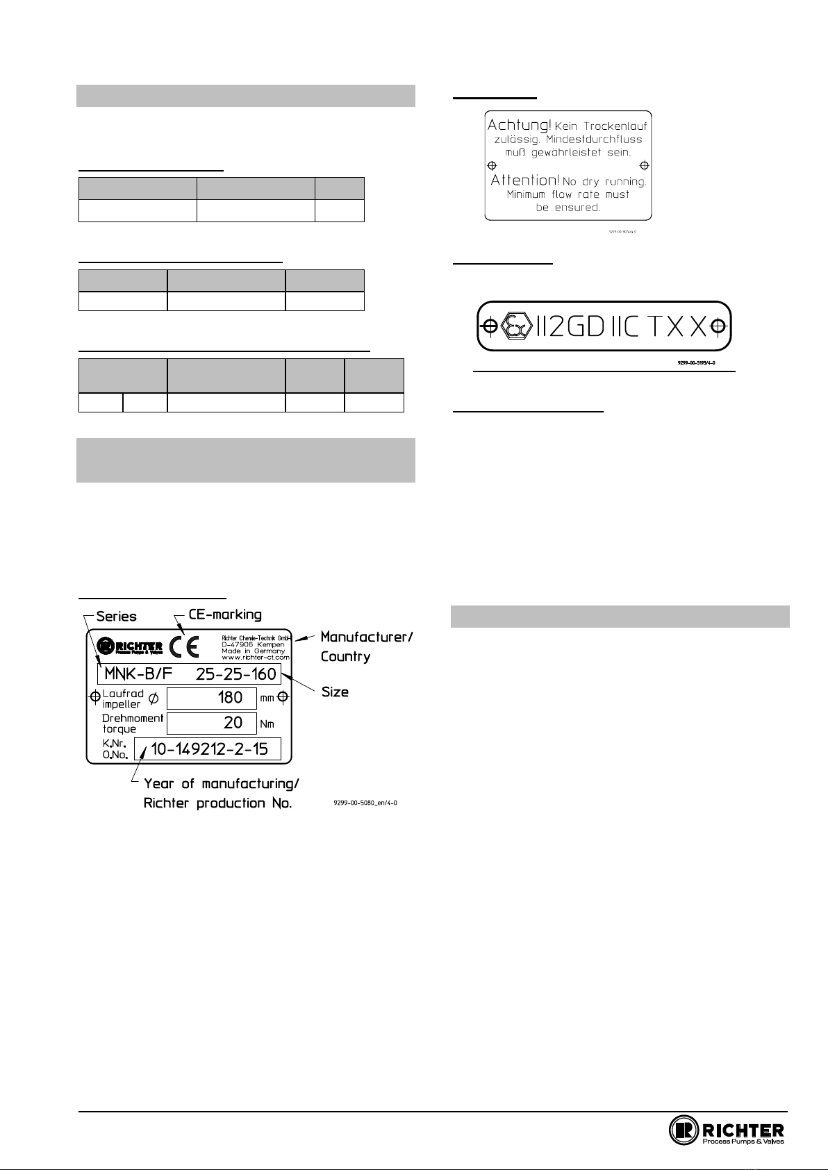
It is imperative to observe signs attached directly to
the pump / unit, e.g.:
Direction of rotation arrow
Warning against dry-running
and they are to be kept legible.
Non-observance of the notes on safety may result
in the loss of any and all claims for damages.
Non-observance may involve the following hazards :
Failure of important functions of the machine/plant.
Failure of electronic equipment and measuring
instruments due to magnetic fields.
Risk to people and their personal property from
magnetic fields.
Risk to people from electric, mechanical and
chemical effects.
Risks to the environment through leaks of
hazardous substances.
If the unit is used in potentially explosive
areas, special attention is to be paid to the
sections identified with “Ex” in this
operating manual.
2.1 Intended use
Richter pumps of the series MNK-B are plastic-lined
magnetic drive centrifugal pumps for the leak-free
conveyance of aggressive, toxic, pure and
inflammable liquids.
The pump is equipped with a permanent magnetic
synchronous drive.
For vertical installation of the pumps, please consult
the manufacturer.
The observance of the specified physical
limits is important for perfect functioning and
safe operation, especially with regard to
explosion protection to prevent potential sources of
ignition (see Section 2.6):
It must be ensured that the pump is always filled
with liquid during operation.
For safe pump operation, we recommend a flow
rate which lies between 0.3 and 1.1 Qopt. The
maximum operating temperature must never be
exceeded. See Section 2.6.7. In case of doubt,
you must consult the manufacturer.
The manufacturer must be consulted in the event
of entrainment of gas >2% as well as solids in
order to avoid a lack of lubrication and dry-running.
The plant NPSH value (NPSHA) should be 0.5 m
higher than the NPSH value of the pump
(NPSHR). See also Section 5.4.1.
Inadmissible modes of operation, even for a
short period, may result in serious damage to
the unit.
In connection with explosion protection, potential
sources of ignition (overheating, electrostatic and
induced charges, mechanical and electric sparks) may
result from these inadmissible modes of operation;
their occurrence can only be prevented by adhering to
the intended use.
Furthermore, reference is made in this connection to
the Directive 95/C332/06 (ATEX 118a) which contains
the minimum regulations for improving the
occupational health and safety of the workers who
may be at risk from an explosive atmosphere.
This unit must not be operated above the
values specified in the data sheet as regards
the fluid to be conveyed, flow rate, speed,
density, delivery head and operating temperature as
well as the motor rating.
The instructions contained in the operating
manual or contract documentation must be
observed; if necessary consult the manufacturer.

Series MNK-B, size 25-25-100 Page 6
9230-056-en Revision 14
TM 9542 Edition 06/2016
All important features are documented in the data
sheet included in the scope of delivery.
In the event of operating conditions other than those
described in the data sheet, the following are to be
checked again:
design of the pump
design of the accessories
resistance of the materials.
2.2 For the customer/operator
The following must be observed:
The notes on safety contained in this operating
manual,
the prevailing regulations on accident prevention,
in-house work, operating and safety regulations of
the customer.
Hot or cold machine parts must be protected by
the customer against being touched.
No protective facilities may be removed when the
machine is in operation.
Hazards due to electricity are to be excluded.
Leaks of hazardous media (e.g. explosive, toxic,
hot) must be removed so that no risk arises for
people and the environment. The statutory
provisions are to be observed.
Caution when using the units in potentially
explosive area! Inadmissible modes of
operation must be prevented.
2.3 For maintenance
In principle, work on the unit may only be performed
when it is at a standstill.
It is imperative to observe the procedure for stopping
the machine described in this operating manual. See
Section 6.3.
Pumps which convey media which are a health
hazard must be decontaminated.
All safety and protective facilities must be remounted
or enabled immediately after the end of work.
In the assemble state, if the safety notes (see also
Section 5.1 and 7.5.2) are observed, the magnetic
drives do not cause any risks or have any affect on
the environment.
During dismantling and assembly as well as
during transport and storage of the magnetic
drives as single components, the notes on
safety in Section 7.5.2 must be observed.
The points listed in Section 6.1 must be followed
before recommissioning.
2.4 Conversion work and
production of spare parts by
the customer
Conversion of or changes to the machine are only
admissible after consultation with the manufacturer.
Original spare parts and accessories authorised by
the manufacturer serve to enhance safety.
The use of other parts may annul the liability for any
resultant consequences.
2.5 Improper operation
The operational safety of the machine supplied is only
guaranteed if it is used properly in accordance with
Section 2.1 of this operating manual.
The operating limits specified in the data sheet must
under no circumstances be exceeded.
2.6 Special requirements for
explosion protection
If the units are used in potentially explosive areas, the
measures and notes in Sections 2.6.1 to 2.6.9 are
imperative to guarantee the explosion protection.
2.6.1 Filling the unit
During pump operation the wetted interior of
the pump must always be filled with the
liquid medium.
This prevents any explosive atmosphere and the risk
of dry-running.
If the customer cannot ensure this, we
recommend that appropriate monitoring
facilities be provided.
All auxiliary, heating and cooling systems
must also be carefully filled.

Series MNK-B, size 25-25-100 Page 7
9230-056-en Revision 14
TM 9542 Edition 06/2016
2.6.2 Special operating conditions
The plain bearings are cooled and lubricated
by a flushing flow.
Owing to properties of the medium (e.g. sticking due
to inadmissible solids entrainment, clogging, gas
entrainment etc.) the cooling flow can be interrupted
and, as a result, an inadmissible temperature rise may
occur. Provide appropriate monitoring facilities. See
Section 5.6.
For safe pump operation, we recommend a flow rate
of 0.3 to 1.1 Qopt. If the pump is operated outside this
range, it must be ensured that the max. admissible
flow rate according to the pump characteristic curve is
not exceeded and that the max. admissible operating
temperature according to Section 2.6.7 is observed.
If the flow rate is too high, the differential pressure
upstream and downstream of the plain bearings could
fall so much that a lack of lubrication or dry-running
may occur.
If the flow rate is too low, the medium may heat up so
much owing to the fluid friction that the max.
admissible surface temperature of the relevant
temperature class is exceeded.
Overloading, overheating or non-observance of the
design data may lead to the decoupling of the
magnetic drive. As a result, eddy currents are induced
on the magnetic drive and the metallic back plate and
an inadmissible rise in temperature may occur.
The situation is to be remedied by providing
appropriate monitoring facilities. See Section 5.6.
The plant NPSH value (NPSHA) should be minimum
0.5 m higher than the NPSH value of the pump
(NPSHR) to prevent a lack of lubrication or dry-
running of the plain bearings.
2.6.3 Chargeable liquids
For operation with chargeable liquids with a
conductivity < 10-8 S/m inert gas must be used
for flushing during evacuation if the lining of
the pump is non-conductive. See Section 6.3.
2.6.4 Identification
The identification on the pump relates to the
pump section. A separate declaration of
conformity must be provided for the shaft
coupling and motor and for other attachments as well
as corresponding identification.
Example of the identification of the pump section:
II2GD IIC TX X.
For assembling the pump with components which are
not explosion-protected (e.g. motor, shaft coupling), it
is recommended to mask or remove the "potentially
explosive" identification from the pump component
and, if necessary, from other accessories.
In this case the declaration of conformity applies
without ATEX identification.
At surface temperatures which depend primarily on
operating conditions, DIN EN 13463-1 Chapter 9.3
allows no temperature class or temperature to be
indicated.
The temperature class must be determined by the
operator in accordance with Section 2.6.7
“Temperature Limits”.
2.6.5 Check of the direction of rotation
If there is also a risk of explosion during the
installation phase, the check of the direction of
rotation must under no circumstances be conducted
by briefly switching on the unfilled pump in order to
prevent an inadmissible rise in temperature at the
plain bearings.
We recommend you to only perform a check
of the direction of rotation with filled pump and
with a rotating field instrument. See also
Section 6.1.2.
2.6.6 Mode of operation of the pump
The pump may only be started with the suction side
shut-off element fully opened and the discharge side
shut-off element slightly opened. Start-up against a
closed check valve is also possible. The discharge
side shut-off element is to be regulated to the
operating design point directly after run-up.
See also Section 5.4.1.
Operation with closed shut-off elements in the
suction and/or discharge lines is not permitted!
There is a risk that even after a short time
high surface temperatures on the pump
housing may occur owing to rapid heating of
the liquid in the pump interior.
A rapid rise in the pressure inside the pump
involves the risk of overloading to the point of
bursting.
The pump must not be in operation in the
unfilled or partially filled state (dry
running). This results in serious damage to
the pump and additional risks to the environment
can arise.
Dry-running cannot only occur with an
insufficiently filled interior but also in the event
of high gas contents in the liquid medium.
Operation of the pump outside the admissible
operating range may also lead to dry-running (e.g.
due to evaporation in the interior).

Series MNK-B, size 25-25-100 Page 8
9230-056-en Revision 14
TM 9542 Edition 06/2016
2.6.7 Temperature limits
In the normal operating condition the highest
temperatures are to be expected on the
surface of the pump housing and on the
stainless steel back plate.
We would like to point out that, under extreme
operating (medium temperature >160 °C) and
ambient conditions (ambient temperature
>30 °C), temperatures of over 130 °C may arise on
the surface of the pump housing.
In the case of media >40° C the surface temperature
of the pump housing is generally lower than the
temperature of the medium as the plastic lining acts
as insulation.
If the pump is heated (e.g. heating jacket), it
must be ensured that the temperature classes
prescribed in the annex are observed.
The not heated pump surface must have free contact
with the environment.
During operation of the pump it must be
ensured that excessive deposits of dust are
prevented (regular cleaning) in order to
prevent the pump surface from heating to above the
admissible temperature.
The plant customer must ensure that the
prescribed operating temperature is observed.
The maximum admissible temperature of the
liquid medium at the pump inlet depends on the
temperature class and the selected lining material
required in each case.
The principle always applies that no inadmissible
temperatures may be introduced into the motor and
that the specifications of the motor manufacturer as
well as VDMA/TVEI 24263 are to be observed.
The temperature limit values of the liquid medium
given in Table 2 are only applicable if motors are used
where the motor manufacturer permits at least the
following surface temperatures for the motor flange
and shaft:
Table 1
Temperature
class
Motor flange
Motor shaft
T6
70 °C
70 °C
T5
70 °C
80 °C
T4
75 °C
85 °C
T3
80 °C
100 °C
T2
80 °C
100 °C
T1
80 °C
100 °C
Observe the figures of the motor manufacturers and
VDMA/ZVEI 24263 on inadmissible ambient
temperatures. If these values are missing, max. 40°C
is to be assumed.
Table 2 below indicates the admissible medium
temperature, depending on the pump design, as a
function of the temperature class in accordance with
EN 13463-1.
Table 2
Temperature
class acc. to
EN 13463-1
Limit value of the temperature
of the liquid
Back plate
CFRP
Back plate
stainless steel
T6 (85 °C)
75 °C 1)
T3 –T6
not certified to
ATEX
T5 (100 °C)
90 °C 1)
T4 (135 °C)
125 °C 1)
T3 (200 °C)
150 °C
T2 (300 °C)
150 °C
150 °C
T1 (450 °C)
150 °C)
150 °C
1) The limit values specified for the temperature of the medium at
the pump inlet are determined for the most unfavourable case
(high speed, low flow, low heat capacity of the medium, ....).
Under favourable operating conditions the limit values specified
may be increased by up to 5 K after consultation with the
manufacturer.
In the case of motors with the ignition protection class
"increased safety", only low surface temperatures are
generally admissible on the motor shaft and on the
motor flange.
In such cases, the max. admissible medium
temperature lies 20 K above the permitted surface
temperature at the interfaces to the motor.
e.g.: max. motor shaft temperature: 60 °C
max. motor flange temperature: 65 °C
This results in an admissible medium temperature at
the pump of 80 °C (60 °C + 20 K).
If values on the admissible ambient temperature are
missing, max. 40 °C is always to be assumed.
2.6.8 Maintenance
For safe and reliable operation, it must be ensured
with regular inspection intervals that the unit is
properly serviced and kept in a perfect technical
condition.
If auxiliary systems (e.g. external flushing, cooling,
heating) are installed, a check must be made to see
whether monitoring facilities are required to safeguard
their operation.
In regard to media containing solids, the maintenance
intervals must be set by the operator in accordance
with the conditions of operation.
2.6.9 Electric peripheral equipment
Electric peripheral equipment, e.g. pressure,
temperature and flow sensors etc. must comply with
the prevailing safety requirements and explosion
protection provisions.
Regular checks of the motor bearings in
accordance with the operating manual of the
motor manufacturer. Observe ATEX notes.

Series MNK-B, size 25-25-100 Page 9
9230-056-en Revision 14
TM 9542 Edition 06/2016
3 Transport, storage and disposal
The pump or the unit must be transported
properly. It must be ensured that during
transport the pump/unit remains in the
horizontal position.
Directly after receipt of the goods, the
consignment must be checked for completeness
and any in-transit damage.
Damaged pumps must not be installed in the plant.
When unpacking magnetic drives as single
parts, the relevant notes in Section 7.5.2
must be observed.
Handle goods carefully to prevent damage.
Flange covers serve as protection during transport
and must not be removed.
If the unit is not installed immediately after delivery, it
must be put into proper storage.
The product should be stored in a dry and vibration-
free, well ventilated room at as constant a
temperature as possible.
Elastomers are to be protected against UV light.
In general, a storage period of 10 years should not
be exceeded. An admissible storage period of 4
years applies to elastomers made of NBR.
If magnetic drives are stored as single parts,
the relevant notes in Section 7.5.2 are to be
observed.
In the case of prolonged storage conservation
agents on machined component surfaces and
packing with a desiccant may be necessary.
3.1 Return consignments
Pumps which have conveyed aggressive or
toxic media must be well flushed and
cleaned before being returned to the
manufacturer's works.
It is imperative to enclose a safety information
sheet / general safety certificate on the field of
application with the return consignment.
Pre-printed forms are enclosed with the installation
and operating manual.
Safety precautions and decontamination methods are
to be mentioned.
3.2 Disposal
Parts of the pump may be contaminated with medium
which is detrimental to health and the environment
and therefore cleaning is not sufficient.
Risk of personal injury or damage to the
environment due to the medium or oil!
Wear protective clothing when work is performed
on the pump.
Prior to the disposal of the pump:
Collect any medium, oil etc. which has escaped
and dispose of it in accordance with the local
regulations.
Neutralise any medium residues in the pump.
Separate pump materials (plastics, metals etc.)
and dispose of them in accordance with the local
regulations.
4 Product description
The sectional drawing shows the set-up of the pump
in the standard design with a back plate made of
stainless steel 1.4301/PFA. See Section 9.
All components which come into contact with the
medium are either plastic-lined or made of other
resistant materials, e.g. silicon carbide.
The housing 100 consists of a metallic shell with a
plastic lining.
The bearing parts are secured against twisting by a
positive connection:
The bearing bushes 545 in the impeller
The right-hand thrust bearing part 393/2 in the
back plate 161
The bearing sleeve 529 in the right-hand thrust
bearing part 393/2
The left-hand thrust bearing part 393/1 in the
bearing sleeve 529
The bearing nut 923/1 with left-hand thread prevents
the bearing components from shifting if axial thrust
occurs in the direction of the suction nozzle.
The back plate 161 is a composite element. The
wetted side is sheathed in plastic. The standard
support structure is made of stainless steel.
As the magnetic drive generates eddy currents in the
stainless steel, the metal around the magnets heats
up. A speed of 2900 rpm and a medium temperature
of 20 °C produce roughly 120 °C in the metal.
The maximum operating pressure is 10 bar. This
back plate made of stainless steel 1.4301/PFA is
not certified for use in the ATEX sector.
As an option, a back plate with a support structure
made of CFRP (carbon-fibre reinforced plastic) is
available. With this design no eddy currents occur and
therefore no elevated temperatures. The maximum
operating pressure is 6 bar.
The flushing flow for the plain bearing lubrication
flows from the impeller rear through the plain bearings
to the suction mouth of the impeller.Additional
information is provided in the brochure.

Series MNK-B, size 25-25-100 Page 10
9230-056-en Revision 14
TM 9542 Edition 06/2016
5 Installation
5.1 Safety regulations
Equipment which is operated in potentially
explosive areas must satisfy the explosion
protection regulations.
People with a pacemaker are at risk from the
strong magnetic field of the magnetic drive. It
may be life-threatening for them to stay at a
distance of less than 500 mm to the pump.
5.2 Installation of pump/unit
The structural work must be prepared in accordance
with the dimensions in the installation drawing.
Method of installation: on a grouted base plate and
firm foundation
Align base plate on the ground foundation.
Insert foundation bolts and grout base plate.
Do not tighten the foundation bolts uniformly and
firmly until the mortar has set.
Other possibilities of alignment are:
4-point-alignment
4-point-alignment with base plate.
As soon as additional installations are
mounted, the stability of the entire unit
installed without a foundation must be
checked.
5.3 Alignment of pump - motor
The following information is of a general
nature. If necessary, special notes of the
motor manufacturer are to be observed.
Prior to alignment work, loosen the screwing 901/6,
920/2 in the lantern. Align the unit with the housing
so that there is no tension and retighten the
screwing.
Use supports in the direct vicinity of the bolts
foundation/base plate.
5.4 Piping
Before the pump is installed, both the suction and
supply lines as well as the discharge line are to be
cleaned.
Dirt or damage to the sealing surfaces is best avoided
if the flange covers remain on the flanges until just
before installation.
Use flange gaskets suitable for the medium.
The screw tightening torques in Section 1.1 are to be
observed for tightening the flange screws.
5.4.1 Nominal size
The operating design point of a centrifugal pump lies
at the intersection of the pump curve and the pipe
curve, see Fig. 2. The pump curve is provided by the
pump manufacturer. The pipe curve is determined
using diagrams or PC programs.
Fig. 1
Under no circumstances can the nominal size of the
piping be derived from the connected nominal size of
the pump.
The pipe nominal size can also be determined using
the flow rate as a rough guide.
The velocity in the suction line should not exceed 2.0
m/s and 5.0 m/s in the discharge line.
When determining the suction line nominal size, the
NPSH value (net positive suction head) must also be
observed. The NPSHR value required for the pump is
specified in the data sheet.
The NPSHR available in the plant
should be at least 0.5 m higher than
the NPSHR required for the pump.
Otherwise, this will lead to a drop in the delivery head,
cavitation or even failure of the pump.
5.4.2 Nozzle loads
The pump can be subjected to nozzle loads in
accordance with ISO 5199.
Changes in the length of the piping caused by
temperature are to be allowed for by appropriate
measures, e.g. the installation of expansion joints.
v m s Q m s
A m
3
2
( / ) = ( / )
( )

Series MNK-B, size 25-25-100 Page 11
9230-056-en Revision 14
TM 9542 Edition 06/2016
5.4.3 Suction line
The suction lines must always be laid on a rising
gradient towards the pump. Otherwise, gas bubbles
may form which considerably reduce the suction line
cross section. Eccentric transition elements must be
installed between different pipe diameters.
Valves which disrupt the course of flow should not be
installed directly upstream of the pump.
Fig. 2
5.4.4 Supply lines
Supply lines should vent towards the reservoir and are
therefore to be laid with a constant downward gradient
towards the pump. Should the piping internals
upstream of the pump be horizontal, a low point can,
of course, be located upstream of these internals.
From here the pipe is then laid with an upward
gradient to the pump so that the gas bubbles which
form here can escape through the pump.
Valves which disrupt the course of flow should not be
installed directly upstream of the pump.
5.4.5 Discharge line
Do not arrange the shut-off valve directly above the
pump but initially provide a transition section.
The discharge nozzle velocity of the medium can –if
necessary –be reduced.
5.4.6 Venting and evacuating
Venting can take place into the discharge line or
upstream of the discharge valve.
A venting line can also be used as a bypass, drain or
flushing line.
The pump housing is fitted with a drain connection as
a standard feature. Optionally, the drain bore can be
drilled.
Fig.3
5.5 Pipe fittings
The following pipe fittings are available from Richter
on request:
Shut-off valves
Check valves
Sight glasses
Priming vessels
Strainers
Pressure gauges
Fig. 4
5.6 Monitoring facilities
Appropriate monitoring facilities are to be
recommended, depending on the
requirements placed on operational safety and
availability of the unit.
Richter provides information on request and can
supply:
Flow meters
Filling level indicators
Motor load monitors
Leak monitors
You can obtain the publications "Safe Operation of
Magnetic Drive Pumps" and "The Operation of
Centrifugal Pumps without NPSH Problems" on
request.
5.7 Drive
The power consumption of the pump at the operating
design point is specified in the data sheet and works
certificate. If the operating design point was not known
when the pump was dispatched, the power
consumption can be read off the appropriate
performance curves. The max. density, the max.
viscosity and a safety margin are to be allowed for.

Series MNK-B, size 25-25-100 Page 12
9230-056-en Revision 14
TM 9542 Edition 06/2016
Care must be taken when selecting the motor size to
ensure that the excess power is not too great. During
start-up the magnetic drive could otherwise stop.
The magnetic drive rating at the nominal speed of
2900 rpm is given in the pump data sheet.
If the motor rating exceeds this magnetic drive rating –
at nominal speed -, it is necessary to check for any
stoppage of the magnetic drive.
This also applies if the required drive rating exceeds
80% of the magnetic drive rating –at nominal speed.
Consult Richter if necessary.
Different operating data can be achieved without
changing the pump through the use of different
speeds, e.g. by means of a frequency converter.
The pump with base plate and motor is illustrated in
the installation drawing.
The operating manual of the motor manufacturer
must be observed.
A motor with a valid ATEX certificate is to be
used if employed in zone 1 and 2.
5.8 Electric connection
The operator is obligated to connect the assembly in
accordance with existing regulations 8 (IEC, VDE,
etc.).
Allow only a trained electrician to perform the
electrical connection.
Compare the existing mains voltage with the
indications on the motor’s manufacturer’s nameplate
and choose a suitable circuit.
A motor protection device (motor-circuit switch) is
urgently recommended.
Danger of explosion if the electrical
installation is incorrect.
In areas at risk of explosion, IEC 60079-14 must also
be observed for the electrical installation.
If the pump is mounted on a base plate, ensuring
electrical conduction through the use of a chopper
disk or contact disk on the housing foot and support
leg.
The assembly must be grounded in accordance with
currently effective regulations, for example, on the
base plate.

Series MNK-B, size 25-25-100 Page 13
9230-056-en Revision 14
TM 9542 Edition 06/2016
6 Commissioning/Shutdown
6.1 Initial commissioning
Normally, the pumps have already been test-run with
water. Unless special agreements have been made,
there could still be residual amounts of water in the
pump. This must be noted in view of a possible
reaction with the medium.
6.1.1 Filling the pump housing
Check to see whether the screws on the suction
flange, discharge flange, housing flange and drain
flange are tightened.
For screw tightening torques see Section 1.1.
Open the suction line fully so that the medium can
flow into the pump.
Open the discharge valve so that the air in the
pump can escape.
If air cannot be vented into the discharge line, e.g.
a drop in pressure in this line is not permitted,
venting must be performed upstream of the
discharge valve.
Monitor the venting operation until no air but only
liquid emerges.
Close the discharge valve again until
only the minimum flow rate is obtained
after the motor has been started.
6.1.2 Start-up
Check the direction of rotation of the
motor with a rotary field instrument.
As viewed from the motor, the direction
of rotation of the pump is clockwise. See also the
direction of rotation arrow of the pump.
If no rotating field instrument is available, the
motor may also be activated briefly, with the
pump filled, so that it does run up. You can
observe the direction of rotation through the fan hood.
The pump must not run dry during the check
of the direction of rotation.
The pump must be completely filled with liquid.
The maximum admissible flow rate must not be
exceeded.
Otherwise the plain bearings can run dry in
both cases.
Switch the motor on.
Set the desired flow by opening the discharge
valve.
When the motor is running but the pump is not
conveying, this means that the magnetic drive
has stopped.
Switch motor off immediately in order to prevent
overheating of the magnet drive and the back
plate.
Then proceeded as follows:
Close discharge valve down to the position
"minimum flow rate".
Start motor again.
If the magnetic drive stops again, look for the cause.
6.2 Operating limits
The operating limits of the pump/unit in terms
of pressure, temperature, power and speed
are entered in the data sheet and it is
imperative to observe them!
6.2.1 Abrasive media
If liquids with abrasive constituents are
conveyed, increased wear at the pump is to
be expected. The inspection intervals should
be reduced compared with the usual times.
6.2.2 Min./max. flow rate
The operating range generally recommended lies at
0.3 Qopt to 1.1 Qopt. Consult the manufacturer for
operation outside this range. and observe Section
2.6.2.
6.3 Shutdown
Close discharge valve down to the position
"minimum flow rate".
Switch motor off.
Close discharge valve completely.
Only close the suction line if the pump is to be
evacuated or dismantled.
For all work on the machine, make sure that
the motor cannot be inadvertently switched
on.
If the pump is to be evacuated or flushed,
observe the local regulations.
If the pump has been operated with a
chargeable liquid, it must be filled with inert
gas (e.g. nitrogen) to prevent an explosive
atmosphere.
It is recommended to wait one hour before the pump
is dismantled from the plant to permit static peak
charges to be eliminated.
These measures are not necessary with pumps with a
conductive plastic lining.
If the pump is returned to the manufacturer's, clean
the pump very thoroughly.
See also Section 3.1.

Series MNK-B, size 25-25-100 Page 14
9230-056-en Revision 14
TM 9542 Edition 06/2016
6.4 Restarting
When the pump is restarted, it must be ensured that
all the relative steps as described in Section 6.1 are
repeated, depending on the progress of the shutdown
operation.
6.5 Improper operation and their
consequences (examples)
Inadmissible modes of operation, even for a
short time, can result in serious damage to the
unit.
In connection with explosion protection, potential
sources of ignition (overheating, electrostatic and
induced charges, mechanical and electric sparks) may
result from these inadmissible modes of operation;
their occurrence can only be prevented by adhering to
the intended use.
Pump is started up without medium :
The plain bearings in the pump may be destroyed.
Other pump components may be destroyed due to
overheating.
Suction line not opened or not opened fully :
Pump is cavitating –material damage to pump and
plain bearings
Pump does not attain the required delivery head or
flow rate.
Pump may be destroyed due to overheating.
Discharge valve closed too much:
Pump may be destroyed due to overheating.
Axial thrust too great.
Discharge valve opened too much:
Pump can cavitate. Particularly severe with an
empty discharge line.
Risk of pressure surge.
Possible damage to the plain bearings.
Magnetic drive may stop.
Motor may be overloaded.
Suction valve and discharge valve closed:
Destruction due to rapid overheating and sharp
rise in pressure.
Control of the pump with the suction valve
Cavitation –the volume may only be regulated on
the discharge side.
Operation with magnetic drive stopped :
If no heat is dissipated, damage to the inner and
drive magnet assemblies may occur.
Overrun of the admissible gas content:
The flow may stop.
Switch pump and vent off for renewed
conveyance.
Make sure that the gas content is not exceeded, as
described in the intended use.

Series MNK-B, size 25-25-100 Page 15
9230-056-en Revision 14
TM 9542 Edition 06/2016
7 Maintenance
7.1 Screw connections of the
housing
After initial loading by the operating pressure and
operating temperature the tightening torques of all
connection screws must be checked at the following
points:
housing flange
suction flange
discharge flange
See also Section 6.1.1, para. 1.
Further checks are to be conducted at regular
intervals in line with the operating requirements.
7.2 Motor
The operating manual of the motor manufacturer must
be observed.
A motor with a valid ATEX certificate is to be
used if employed in zone 1 and 2.
Observe the ATEX notes of the motor manufacturer.
7.3 Cleaning
Care must be taken when cleaning the pump to
ensure that it is not exposed to a strong water jet.
7.4 Stand-by pumps
If a pump is on stand-by, it is to be started up from
time to time.
This operation is to be performed more often for
pumps which are exposed to very strong vibrations
from the plant.
When dismantling the pump from the plant, drain it,
thoroughly clean it, seal with flange covers and store
in accordance with the instructions.
7.5 Notes on dismantling
All repair and maintenance work is to be performed
by skilled staff using appropriate tools and original
spare parts.
Is the necessary documentation available?
Has the pump been taken out of operation,
evacuated and flushed correctly? See also
Section 6.3.
If no new assembly is performed immediately after
dismantling, the plastic and ceramic components in
particular must be stored carefully.
7.5.1 Protective clothing
Even if the pump has been properly evacuated and
flushed, residue of the medium may still remain in the
pump, e.g. between sealing surfaces or in the bearing
seats or in the can or the can insert.
Plastic components may absorb medium
which gradually emerges from the material
after flushing.
Proper protective clothing is to be worn.
Protective clothing is also to be worn even if only the
bearing pedestal is to be removed. Medium may
penetrated the lantern chamber through the can.
7.5.2 Magnetic fields
Caution ! Strong magnetic fields
Risk during dismantling and in the vicinity of
magnetic drives as single parts.
Remove loose parts and other magnetisable metals
from the work bench. They could otherwise be
attracted: Risk of accident!
Place any tools needed at a safe distance.
Keep electronic equipment and measuring
instruments at a distance. In cases of doubt consult
the equipment manufacturer.
Hold magnetic drives as single parts firmly or secure.
Otherwise they could be attracted, for example, by a
vice: Risk of accident!
People with an artificial pacemaker
Keep torso at a minimum distance of
500 mm.
For safety's sake, a distance of 150 mm should be
observed for watches, electric data carriers, data
carriers with magnetic strips etc.

Series MNK-B, size 25-25-100 Page 16
9230-056-en Revision 14
TM 9542 Edition 06/2016
7.6 Dismantling
There are two possibilities for dismantling:
1. Dismantling the complete pump from the plant.
2. Dismantling the complete slide-in unit as the pump
housing can remain in the plant connected to the
piping.
Dismantling of the complete pump is described here.
The operating torque of the magnetic coupling
installed is specified on the type plate.
Undo housing screws 901/3, 554/9.
Remove entire slide-in unit with motor.
If the housing remains in the plant, leave the
housing gasket in the centering to protect the
housing sealing surface.
7.6.1 Dismantling the slide-in unit
Secure slide-in unit on the work bench or a work
top.
Remove intermediate ring 509/1.
Remove back plate 161 with impeller 230 and
bearings.
Remove bearing nut 923. Note: left-hand thread!
Remove left-hand thrust bearing part 393/1.
Remove impeller 230 with bearing bushes 545/1
and 545/2.
If necessary, remove bearing bushes 545/1, 545/2
and distance washers 551/1, 551/2 from the
impeller.
Remove bearing sleeve 529/1.
Remove right-hand thrust bearing part 393/2.
Keep the bearing bushes 545 how installed.
7.6.2 Dismantling of drive unit
The magnets on the flywheel mass are now exposed.
They are every brittle and therefore sensitive
to shocks or impacts.
If no further dismantling of the lantern, motor
and flywheel mass takes place, the magnets must be
well protected, e.g. by a plastic disc which is inserted
into the centering of the lantern.
Remove hex. screw 901/9 with disc 550/1.
Pull flywheel mass 599 off the motor shaft.
Unscrew lantern 344 with hex. socket screw 914/3
and washer 554/8 off the motor.
7.7 Notes on assembly
Use original spare parts. See also Section 2.4.
Do not use any defective parts.
Has the pump been shut down, drained and
flushed in accordance with the regulations?
See also Section 6.3.
Apply Anti-Seize-Special assembly paste (e.g.
from Weicon) to fitted surfaces (not stainless steel
parts).
Check whether all parts fit and only then assemble.
Important dimensions (centerings, bearing fits or
bearing play) are to be checked prior to assembly;
perform a trial assembly if required.
It is recommended to replace the housing gasket
401 during assembly.
Many metallic particles adhering to magnetic
components such as the inner magnet assembly
859 and drive magnet assembly 858 must be
removed prior to assembly. For this purpose
simple plasticene can be used..
A complete assembly process is described in the
following.
Sub-sections can be deduced from this.
See also Section 7.5.
7.8 Assembly
7.8.1 Assembly of drive unit
Screw lantern 344 with hex. socket screw 914/3
and washer 554/8 to motor.
Push flywheel mass 599 right onto the motor shaft
and screw together with disc 550/1 and hex. screw
901/9.
7.8.2 Assembly of slide-in unit
Clamp the metallic hub of the back plate 161 in a
vice.
Install right-hand thrust bearing part 393/2.
Install bearing bush 529/1.
7.8.3 Trial assembly of impeller and
bearing bush
Install bearing bushes 545/1 and 545/2 in the
impeller 230 and press tight together.
Push this unit onto the bearing sleeve 529/1.
Install left-hand thrust bearing part 393/1.
Screw on bearing nut 923. Left-hand thread.

Series MNK-B, size 25-25-100 Page 17
9230-056-en Revision 14
TM 9542 Edition 06/2016
7.8.4 Determine thicknesses S1and S2of
the distance washers 551
Fig. 5
The distances X and Z are given in the works
certificate.
X: Distance behind the impeller
Z: Axial clearance of the plain bearings
Press inner magnet assembly in the direction of
the impeller.
Measure distance X1behind the impeller.
Press impeller in the direction of the motor.
Measure distance X2behind the impeller.
Thickness of the distance washer on the inner magnet
assembly side: S1= X1- X
Thickness of the distance washer on the impeller side:
S2= X - X2-Z
Example
Figures in the works certificate (mm) : X= 2.0
Z= 0.4
Measurements during trial assembly : X1 = 2.5
X2 = 1.3
S1= X1–X = 2.5 - 2.0 = 0.5 mm
S2= X - X2–Z = 2.0 - 1.3 - 0.4 = 0.3 mm
Dismantling of impeller and bearing bushes.
7.8.5 Final assembly
Final assembly of impeller 230, bearing bushes
245/1, 245/2 and distance washers 551/1, 551/2.
Assembly with the back plate 161.
Insert the back plate with the impeller 230 into the
lantern 344.
Insert intermediate ring 509/1 into the lantern 344.
Insert housing gasket 401.
Screw housing 100 to slide-in unit.
The works certificate also indicates the distance Y.
Y : Distance in front of the impeller
This distance can be influenced by the thickness of
the housing gasket.
When tightening the housing screws, observe the
tightening torques in Section1.1.
After tightening the housing screws 901/3, 554/9
the support screws (901/6, 554/6) in the support
bracket of the lantern 344 are to be brought into
contact and counter-checked with the nuts 920/2.
7.9 Tests
The pumps are tested with water at the
manufacturer's.
The operating data measured are documented in a
works certificate.
If, during a test after repairs, discrepancies compared
with the works certificate are discovered, the following
people can be called in :
1) in-house pump office
2) The manufacturer Richter
or its local agent
The following conveying data can be checked using
the pump performance curves:
Flow rate
Head
Power requirement
NPSHR
9299-00-5058.4-00.1
X
S
S
Z
1
2

Series MNK-B, size 25-25-100 Page 18
9230-056-en Revision 14
TM 9542 Edition 06/2016
8 Faults
Faults may result from inadmissible modes of
operation. Such inadmissible modes of
operation –even brief ones –may cause
serious damage to the unit.
In connection with explosion protection, potential
sources of ignition (overheating, electrostatic and
induced charges, mechanical and electric sparks) can
result from these inadmissible modes of operation;
their occurrence can only be prevented by adhering to
the intended use.
See also Section 6.5.
Should there be any uncertainty about the remedy to
be applied, please inquire at the in-house pump office
or at the pump manufacturer's.
No delivery :
Is the pump filled and vented?
Is the suction line open, vented, cleaned and
correctly laid?
Is the discharge line open, vented, cleaned and
correctly laid?
Is the geodetic head too high?
Is air being drawn in?
Has the magnetic drive stopped?
Flow rate too low :
Have the pump, suction line and discharge line
been completely vented, filled and cleaned?
Have any strainers installed been cleaned?
Are all shut-off devices open?
Is the geodetic head too high?
Is the NPSHA too low or the NPSHR too high?
Are the pipe resistances too high?
Is the viscosity too high?
Is the direction of rotation correct?
Is the speed too low or the impeller diameter too
small?
Are pump parts worn?
Gas in the medium?
Flow rate too high :
Is the geodetic head too low?
Are the pipe or nozzle resistances too low?
Is the pump speed too low or the impeller diameter
too large?
Delivery pressure too high :
Is the speed too high or the impeller diameter too
large?
Is the density too high?
Motor consumes too much electricity :
Is the flow rate, density or viscosity too high?
Is the speed too high or the impeller diameter too
large?
Can the pump shaft be turned properly?
Pump does not run smoothly or creates noises :
Are the rolling bearings of the motor damaged?
Are parts of the hydraulics damaged?
Is the flow rate too low or too high?
Is the impeller balanced?
Is the pump twisted?
Is there foreign matter in the pump?
Leak from the pump :
Are all screws tightened to the correct tightening
torque?
Were the sealing surfaces assembled in a clean
state?
Have approved gaskets been installed?

Series MNK-B, size 25-25-100 Page 19
9230-056-en Revision 14
TM 9542 Edition 06/2016
9 Sectional drawing MNK-B, size 25-25-100
(with back plate mades of stainless steel 1.4301/PFA)
100 housing
122 blind cover
161 back plate with axle
230 impeller
344 lantern
393/x thrust bearing part
401 housing gasket
415/1 centering gasket
509/1 intermediate ring
529/3 bearing sleeve
545/x bearing bush
550/1 disc
551/x distance washer
554/x washer
599 flywheel mass
800/1 motor
901/x hex. screw
902/1 stud screw
914/3 hex. socket screw
920/x hex. nut
923 bearing nut
X, Y, Z see work's certificate

Modification techniques possibles sans réservées!
Graphique non à l'échelle!
Dimensions valables uniquement revêtues d'une signature!
This leaflet is subject to alteration!
Drawing not to scale!
Certified for construction purposes only when signed!
Technische Änderungen vorbehalten!
Nicht maßstäblich!
Maße nur mit Unterschrift verbindlich!
CHEMIENORMPUMPEN / CHEMICAL PROCESS PUMPS / POMPE POUR L'INDUSTRIE CHIMIQUE
Baureihe/Series/Série Ausführung Magnetkupplungspumpen
Design Magnet drive pumps
Construction Pompes à entraînement magnétique
9200-00-3030/4-04 © Richter Chemie-Technik GmbH
TM 9601 - 1 -
MNK
MNK-B
Einsatzgrenzen / operating limits
Baugrößen / Size: 25-25-125, 50-32-125, 50-32-200, 65-40-200, 80-50-200
Table of contents
Other Richter Water Pump manuals

Richter
Richter MNK-X User manual

Richter
Richter V&A RMI Series User manual

Richter
Richter MNKA Series User manual

Richter
Richter SCK Series User manual

Richter
Richter MNK-B Setup guide

Richter
Richter SCK Series User manual

Richter
Richter SAFERUN User manual

Richter
Richter SCK Series User manual

Richter
Richter MNKA Series User manual

Richter
Richter MNK Series User manual